EP0628697B1 - Mit seil zu bewegende rollgardine - Google Patents
Mit seil zu bewegende rollgardine Download PDFInfo
- Publication number
- EP0628697B1 EP0628697B1 EP94900996A EP94900996A EP0628697B1 EP 0628697 B1 EP0628697 B1 EP 0628697B1 EP 94900996 A EP94900996 A EP 94900996A EP 94900996 A EP94900996 A EP 94900996A EP 0628697 B1 EP0628697 B1 EP 0628697B1
- Authority
- EP
- European Patent Office
- Prior art keywords
- tube
- pulley
- screen
- rotary shaft
- fitted
- Prior art date
- Legal status (The legal status is an assumption and is not a legal conclusion. Google has not performed a legal analysis and makes no representation as to the accuracy of the status listed.)
- Expired - Lifetime
Links
Images

Classifications
-
- E—FIXED CONSTRUCTIONS
- E06—DOORS, WINDOWS, SHUTTERS, OR ROLLER BLINDS IN GENERAL; LADDERS
- E06B—FIXED OR MOVABLE CLOSURES FOR OPENINGS IN BUILDINGS, VEHICLES, FENCES OR LIKE ENCLOSURES IN GENERAL, e.g. DOORS, WINDOWS, BLINDS, GATES
- E06B9/00—Screening or protective devices for wall or similar openings, with or without operating or securing mechanisms; Closures of similar construction
- E06B9/56—Operating, guiding or securing devices or arrangements for roll-type closures; Spring drums; Tape drums; Counterweighting arrangements therefor
- E06B9/60—Spring drums operated only by closure members
-
- E—FIXED CONSTRUCTIONS
- E06—DOORS, WINDOWS, SHUTTERS, OR ROLLER BLINDS IN GENERAL; LADDERS
- E06B—FIXED OR MOVABLE CLOSURES FOR OPENINGS IN BUILDINGS, VEHICLES, FENCES OR LIKE ENCLOSURES IN GENERAL, e.g. DOORS, WINDOWS, BLINDS, GATES
- E06B9/00—Screening or protective devices for wall or similar openings, with or without operating or securing mechanisms; Closures of similar construction
- E06B9/56—Operating, guiding or securing devices or arrangements for roll-type closures; Spring drums; Tape drums; Counterweighting arrangements therefor
-
- E—FIXED CONSTRUCTIONS
- E06—DOORS, WINDOWS, SHUTTERS, OR ROLLER BLINDS IN GENERAL; LADDERS
- E06B—FIXED OR MOVABLE CLOSURES FOR OPENINGS IN BUILDINGS, VEHICLES, FENCES OR LIKE ENCLOSURES IN GENERAL, e.g. DOORS, WINDOWS, BLINDS, GATES
- E06B9/00—Screening or protective devices for wall or similar openings, with or without operating or securing mechanisms; Closures of similar construction
- E06B9/56—Operating, guiding or securing devices or arrangements for roll-type closures; Spring drums; Tape drums; Counterweighting arrangements therefor
- E06B9/78—Operating, guiding or securing devices or arrangements for roll-type closures; Spring drums; Tape drums; Counterweighting arrangements therefor for direct manual operation, e.g. by tassels, by handles
-
- E—FIXED CONSTRUCTIONS
- E06—DOORS, WINDOWS, SHUTTERS, OR ROLLER BLINDS IN GENERAL; LADDERS
- E06B—FIXED OR MOVABLE CLOSURES FOR OPENINGS IN BUILDINGS, VEHICLES, FENCES OR LIKE ENCLOSURES IN GENERAL, e.g. DOORS, WINDOWS, BLINDS, GATES
- E06B9/00—Screening or protective devices for wall or similar openings, with or without operating or securing mechanisms; Closures of similar construction
- E06B9/56—Operating, guiding or securing devices or arrangements for roll-type closures; Spring drums; Tape drums; Counterweighting arrangements therefor
- E06B9/80—Safety measures against dropping or unauthorised opening; Braking or immobilising devices; Devices for limiting unrolling
- E06B9/82—Safety measures against dropping or unauthorised opening; Braking or immobilising devices; Devices for limiting unrolling automatic
- E06B9/90—Safety measures against dropping or unauthorised opening; Braking or immobilising devices; Devices for limiting unrolling automatic for immobilising the closure member in various chosen positions
-
- E—FIXED CONSTRUCTIONS
- E06—DOORS, WINDOWS, SHUTTERS, OR ROLLER BLINDS IN GENERAL; LADDERS
- E06B—FIXED OR MOVABLE CLOSURES FOR OPENINGS IN BUILDINGS, VEHICLES, FENCES OR LIKE ENCLOSURES IN GENERAL, e.g. DOORS, WINDOWS, BLINDS, GATES
- E06B9/00—Screening or protective devices for wall or similar openings, with or without operating or securing mechanisms; Closures of similar construction
- E06B9/56—Operating, guiding or securing devices or arrangements for roll-type closures; Spring drums; Tape drums; Counterweighting arrangements therefor
- E06B9/80—Safety measures against dropping or unauthorised opening; Braking or immobilising devices; Devices for limiting unrolling
- E06B9/82—Safety measures against dropping or unauthorised opening; Braking or immobilising devices; Devices for limiting unrolling automatic
- E06B9/90—Safety measures against dropping or unauthorised opening; Braking or immobilising devices; Devices for limiting unrolling automatic for immobilising the closure member in various chosen positions
- E06B2009/905—Safety measures against dropping or unauthorised opening; Braking or immobilising devices; Devices for limiting unrolling automatic for immobilising the closure member in various chosen positions using wrap spring clutches
Definitions
- the present invention relates to improvements in a roll blind of which the screen is pulled down by hand and rolled up by a wind-up spring.
- JP Y S63-41516 and JP Y H1-26871 disclose the roll blind of which the screen is pulled down by hand and rolled up by the winding spring.
- the roll blind comprises a tube for rolling up the screen thereon, a fixed shaft for rotatably supporting one end portion of the tube, a wind-up spring interposed between the tube and the fixed shaft, a clutch brake interposed between the tube and the fixed shaft for selectively rotating the tube.
- the screen is usually provided at its free end with a weight bar.
- the clutch brake allows the tube to roll down the screen therefrom, when the weight bar is pulled down.
- the clutch brake prevents the tube from rolling the screen down therefrom and up thereon, when the weight bar is released after being substantially lowered.
- the clutch brake again allows the tube to be rotated by the wind-up spring in the direction in which the screen is rolled up on the tube, when the weight bar is released after being slightly lowered. While the screen is rolled up by the winding spring, its speed can be reduced by the use of a reduction mechanism interposed between the tube and the fixed shaft.
- the clutch brake as described above is disclosed by JP B S63-34950.
- the aforementioned reduction mechanism is disclosed by JP Y H1-26871.
- the weight bar When the roll blind is mounted in a tall window extending from floor to ceiling, the weight bar is usually provided with a pulling string.
- the string enables one to operate the roll blind even if the screen is rolled up at a high position beyond one's reach. However, when the screen is lowered near the floor, the string inconveniently lies at full length on the floor.
- EP-A-0 481 688 is providing a corded roll blind in which a pulling string is eliminated from the weight bar.
- the present invention is intended to improve such design.
- the present invention consists in a roll blind according to claim 1.
- the clutch brake When the weight bar or endless pulling member is drawn down in the direction in which the screen is rolled down, the clutch brake allows the tube to rotate in the direction in which the screen is rolled down therefrom. When the weight bar or the pulling member is released after being substantially drawn, the clutch brake prevents the tube from rotating, so that the weight bar remains at a position lowered from the initial position. When the weight bar or the pulling member is released after being slightly drawn, the clutch brake again allows the tube to be rotated by the wind-up spring in the direction in which the screen is rolled up on the tube.
- the conventional pulling string is eliminated from the weight bar, because the endless pulling member is always hung from the pulley at an easily operatable position.
- the reduction mechanism can be removed from the blind, if the endless pulling member always moves together with the tube when the screen is rolled up on the tube. The reason for this is that one can reduce the wind-up speed by giving a hand-touch friction to the endless pulling member. But, this results to that the one-way clutch device is removed from the blind.
- the advantages offered by the present invention are that one can operate the screen of the roll blind by either of the weight bar and the endless pulling member attached to the weight bar and that the endless pulling member always hangs at an easily operatable position higher than the floor. Accordingly, the weight bar is free from the conventional pulling string which inconveniently lies on the floor when the screen is rolled down near the floor.
- the roll blind further comprises a one-way clutch interposed between the tube and the pulley so that the pulley can rotates the tube when the endless pulling member is drawn in the direction in which the screen is rolled down but not when drawn in the counter direction. When the endless pulling member is drawn in the counter direction by mistake, the pulley rotates idle so that no undesirable torque acts on the clutch brake.
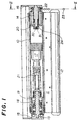
- the roll blind has a tube 10 on which a screen 11 is rolled up.
- the screen 11 has its free end attached to a weight bar 12.
- the tube 10 has one end portion fitted on a fixed shaft 13 and the other end portion fitted on a rotary shaft 14.
- the fixed shaft 13 is fixedly supported by a bracket 15.
- the rotary shaft 14 is rotatably supported by the other bracket 16.
- the fixed shaft 13 has its inner end extending axially to a fixed part of a reduction gearing mechanism 17, of which the rotary part is connected to the inner surface of the tube 10 for rotation therewith.
- the one end portion of the tube 10 is fixedly fitted on an annular end piece 19.
- a clutch brake 18 has its fixed part fixedly fitted on the fixed shaft 13 and the rotary part connected to the inner surface of the annular end piece 19.
- a wind-up spring 21 is loosely fitted on the fixed shaft 13 and has one end thereof secured to the fixed shaft 13 and the other end attached to the end piece 19 of the tube 10.
- the clutch brake is the same as disclosed by JP B 63-34950.
- the aforementioned construction is similar to that used in the conventional clutch-brake type roll blind with a wind-up spring for rolling up a screen on a tube.
- a pulley 22 is rotatably fitted on the rotary shaft 14 projecting from the other end of the tube 10.
- a ball chain 23 is drivingly engaged on the pulley 22.
- the ball chain hangs down at a position in which one can operate the chain with ease.
- the other end portion of the tube has the inner surface thereof is secured to the other annular end piece 20, which is joined with the rotary shaft 14 for rotation therewith through the intermediary of a key 30 and a key groove 31.
- the key 30 and the key groove 31 are diametrally provided on the respective inner end surfaces of the end piece 20 and the rotary shaft 14 and detachably coupled with each other.
- a coil-spring type one-way clutch 24 is provided between the pulley 22 and the rotary shaft 14.
- the roll blind of the present invention has no pulling string as required for the conventional roll blind.
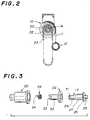
- the rotary shaft 14 has an outer axle 25 put into a bore in the bracket, a flange 26 in contact with the outer face of the pulley 22, a central axle 27 for rotatably fitted in the bore of the pulley 22, and an inner axle 28 fitted in the coil spring of the one-way clutch 24.
- the inner axle 28 is formed at its end with a key groove 31 for coupling engagement with a key provided in the inner periphery of the end piece 20.
- the inner axle 28 of the rotary shaft 14 is diametrally smaller than the axle.
- the pulley 22 has its sleeve portion 32 extending to the inner axle 28 of the rotary shaft 14.
- the inner axle 28 is loosely fitted in the coil spring of the one-way clutch 24.
- the sleeve portion 32 at the inner end is formed with a slit 33 for fitting engagement with one end 34 of the coil spring of the one-way clutch 24.
- the coil spring type one-way clutch 24 is so arranged that it tightly coils on the inner axle 28 of the rotary shaft 14 when the slit 32 causes the one end 34 to turn in the direction in which the screen is rolled down from the tube and uncoils from the inner axle 28 when the slit 32 causes the end 34 to turn in the counter direction. Accordingly, the pulley 22 is rotated in the direction in which the screen is drawn out, the coil spring type one-way clutch 24 allows the rotary shaft 14 or the tube to be rotated by the pulley 22.
- the clutch device 24 prevents the rotary shaft 14 or the tube from being rotated by the pulley 22 with the result that the pulley 22 fails to rotate the pulley 22 idles on the rotary shaft 14.
- the coil spring 24 uncoils from the rotary shaft 14 with the result that the pulley 22 idles on the rotary shaft 14 without rotating the tube 10.
- the coil spring type one-way clutch may be substituted for any other type one-way clutch.
- the weight bar 12 When the weight bar 12 is within one's reach, one can operate either of the weight bar 12 and the the ball chain to raise and lower the screen.
- the pulley 22 When one pulls down the weight bar 12 to roll down the screen 11 from the tube 10, the pulley 22 will rotate together with the tube 10 if the ball chain is not prevented from moving. But, if the ball chain is prevented from moving by hand, the coil spring 24 uncoils from the rotary shaft so that the pulley 22 remains unmoved and slips on the rotary shaft.
- the blind of FIG. 4 is provided with neither one-way clutch nor reduction gearing mechanism. It has a tube 10 secured to such an end piece 20 that is integrally formed with the rotary shaft 14 and the pulley 22.
- the ball chain 23 always moves together with the tube 10.
- the ball chain 23 always hangs at a position in which one can operate it with ease to raise or lower the screen 11.
- the conventional pulling string as attached to the weight bar 12 even if the roll blind is mounted in such a tall window that the weight bar is raised up beyond one's reach.
- the roll blind of the invention is used as a manually operatable shade for a window in a house, and suitable in particular to control the light from a tall window extending to ceiling.
Landscapes
- Engineering & Computer Science (AREA)
- Structural Engineering (AREA)
- Architecture (AREA)
- Civil Engineering (AREA)
- Operating, Guiding And Securing Of Roll- Type Closing Members (AREA)
Claims (2)
- Mit Seil versehene Rollgardine mit einem Rohr (10) zum Aufrollen einer Abschirmung (11), einer fixierten Welle (13) zum drehbaren Abstützen eines ringförmigen Endteiles (19), das fest in einen Endabschnitt des Rohres eingepaßt ist, einer Kupplungsbremse (18) zwischen dem Rohr und der fixierten Welle, um das Rohr wahlweise zu drehen, einer Aufwickelfeder (21), die zwischen dem Rohr und der fixierten Welle angeordnet ist, um das Rohr in die Richtung zu drehen, in welcher die Abschirmung auf das Rohr aufgerollt wird, einer Drehwelle (14), die in das andere ringförmige Endteil (20) eingepaßt ist, das fest in den anderen Endabschnitt des Rohres eingepaßt ist, um sich damit zu drehen und sich teilweise davon erstreckt, einem Paar Träger (15, 16) zum Abstützen der fixierten Welle und der Drehwelle, einer Seilscheibe (22), die drehbar auf der Drehwelle sitzt und damit unter Zwischenschaltung einer Schraubenfeder (24) der Art einer Einwegekupplung gekoppelt ist und mit einem Endloszugglied (23), das antreibbar von der Seilscheibe herabhängt, so daß die Seilscheibe das Rohr (10) nur dann drehen kann, wenn das Zugglied (23) in die Richtung gezogen wird, in welcher die Abschirmung (11) abwärts gerollt wird,
dadurch gekennzeichnet,
daß die Drehwelle (14) eine äußere Achse (25), welche in eine Bohrung in dem Träger (16) eingesetzt ist, einen Flansch (26) in Kontakt mit der äußeren Fläche der Seilscheibe (22), eine mittlere Achse (27), die drehbar in der Bohrung der Seilscheibe (22) sitzt und eine innere Achse (28) aufweist, welche im Durchmesser kleiner als die Mittelachse (27) ist und in der Schraubenfeder (24) sitzt, daß die innere Achse (28) mit einer Keilausnehmung (31) zum Kupplungseingriff mit einem Keil (30) ausgebildet ist, der in dem inneren Umfang des anderen Endteiles (20) vorgesehen ist, daß die Seilscheibe (22) einen Hülsenabschnitt (32), der drehbar auf der Mittelachse (27) sitzt und einen Schlitz (33) aufweist, welcher in dem Hülsenabschnitt zwecks Eingriffes mit einem Ende (34) der Schraubenfeder (24) ausgebildet ist, so daß die Schraubenfeder (24) sich auf der Drehwelle aufwickelt, wenn sich die Seilscheibe in die Richtung dreht, in welcher die Abschirmung abwärts gerollt wird und sich von der Drehwelle abwickelt, wenn sich die Seilscheibe in gegengesetzte Richtung dreht. - Rollgardine nach Anspruch 1, dadurch gekennzeichnet, daß das Zugglied eine Kugelkette (23) ist.
Applications Claiming Priority (5)
| Application Number | Priority Date | Filing Date | Title |
|---|---|---|---|
| JP82200/92U | 1992-11-30 | ||
| JP8220092U JPH0645087U (ja) | 1992-11-30 | 1992-11-30 | コード操作可能なロールブラインド |
| JP5092799A JPH06212867A (ja) | 1992-11-30 | 1993-04-20 | コード操作可能なロールブラインド |
| JP92799/93 | 1993-04-20 | ||
| PCT/JP1993/001713 WO1994012757A1 (en) | 1992-11-30 | 1993-11-24 | Cord operable roll blind |
Publications (3)
| Publication Number | Publication Date |
|---|---|
| EP0628697A1 EP0628697A1 (de) | 1994-12-14 |
| EP0628697A4 EP0628697A4 (de) | 1995-05-03 |
| EP0628697B1 true EP0628697B1 (de) | 1997-05-14 |
Family
ID=26423216
Family Applications (1)
| Application Number | Title | Priority Date | Filing Date |
|---|---|---|---|
| EP94900996A Expired - Lifetime EP0628697B1 (de) | 1992-11-30 | 1993-11-24 | Mit seil zu bewegende rollgardine |
Country Status (5)
| Country | Link |
|---|---|
| US (1) | US5542464A (de) |
| EP (1) | EP0628697B1 (de) |
| JP (1) | JPH06212867A (de) |
| DE (1) | DE69310718T2 (de) |
| WO (1) | WO1994012757A1 (de) |
Families Citing this family (34)
| Publication number | Priority date | Publication date | Assignee | Title |
|---|---|---|---|---|
| US5669432A (en) * | 1996-03-28 | 1997-09-23 | Nisenson; Jules | Automatic-locking mechanical drive construction |
| CA2256569C (en) * | 1996-05-23 | 2005-07-05 | Sunproject S.R.L. | Elastic means for rolling up a roller curtain |
| US5791393A (en) * | 1997-03-31 | 1998-08-11 | Judkins; Ren | Shade operator |
| US5887637A (en) * | 1997-05-05 | 1999-03-30 | Phyper; Duncan | Aperture covering system |
| US5938139A (en) * | 1997-11-05 | 1999-08-17 | Lin; Cheng-Tai | Manually operated screen reeling device |
| US5927370A (en) * | 1997-11-18 | 1999-07-27 | Judkins; Ren | Release brake shade operator |
| US6129131A (en) * | 1997-11-26 | 2000-10-10 | Hunter Douglas Inc. | Control system for coverings for architectural openings |
| JP3524738B2 (ja) * | 1997-11-27 | 2004-05-10 | 株式会社ニチベイ | ロールスクリーン |
| US6142211A (en) * | 1999-08-10 | 2000-11-07 | Judkins; Ren | Shade operator with release brake |
| IT1316456B1 (it) * | 2000-02-11 | 2003-04-22 | Bettio Group Srl | Testata con perno dissociabile particolarmente per zanzariera estruttura di zanzariera cosi' ottenuta. |
| DK200001534A (da) * | 2000-10-13 | 2002-04-14 | Fabers Fab As C | En hæve- og sænkemekanisme, især til rullegradiner |
| FR2837865B1 (fr) * | 2002-03-28 | 2005-07-29 | Simu | Mecanisme de manoeuvre et installation de fermeture ou de protection solaire incorporant un tel dispositif |
| FR2837864B1 (fr) * | 2002-03-28 | 2004-06-11 | Simu | Mecanisme de tension d'un ressort de compensation pour installation de fermeture ou de protection solaire |
| KR100635350B1 (ko) * | 2002-10-07 | 2006-10-17 | 세이키 주코 가부시키가이샤 | 자동 권취식 스크린장치 |
| GB2397292A (en) * | 2003-01-15 | 2004-07-21 | Nifco Inc | Unidirectional brake for a winding mechanism |
| ITTO20030917A1 (it) * | 2003-11-20 | 2004-02-19 | Gianus Spa | Sistema di tirella a scomparsa per schermo avvolgibile. |
| JP4685002B2 (ja) * | 2004-06-14 | 2011-05-18 | セイキ住工株式会社 | 横引きロール網戸 |
| JP4440802B2 (ja) | 2005-02-28 | 2010-03-24 | 株式会社ニチベイ | ブラインド |
| KR100754441B1 (ko) | 2005-07-05 | 2007-09-03 | (주)한국윈텍 | 멀티 쉐이드장치 |
| WO2007004852A1 (en) * | 2005-07-05 | 2007-01-11 | Wintec Korea Inc. | Multiple choice shade system |
| KR100658640B1 (ko) | 2006-02-06 | 2006-12-19 | 곽재석 | 롤 스크린의 자동 승강 구동장치 |
| US20080067274A1 (en) * | 2006-09-18 | 2008-03-20 | Cannaverde Joseph A | Window treatment system with a single cord |
| US20080230191A1 (en) * | 2007-01-12 | 2008-09-25 | Philip Ng | Roller Clutch Assembly |
| JP4897518B2 (ja) | 2007-03-02 | 2012-03-14 | 株式会社ニチベイ | ブラインドの操作装置 |
| CN101021143B (zh) * | 2007-03-22 | 2011-05-04 | 朱晓荧 | 一种卷帘用自动释放窗帘布的方法及机构 |
| US20090078380A1 (en) * | 2007-09-26 | 2009-03-26 | Li-Ming Cheng | Damping apparatus for retraction and extension of window shades |
| CN104196434B (zh) * | 2014-08-29 | 2016-02-10 | 王芳明 | 一种卷帘控制器及窗帘 |
| CN105804616B (zh) * | 2015-01-30 | 2017-07-14 | 福建固美金属有限公司 | 一种手动卷帘式窗户的开关方法 |
| US9593530B1 (en) | 2015-08-18 | 2017-03-14 | Hunter Douglas Inc. | Brake assembly for a covering for an architectural opening |
| US9631425B2 (en) * | 2015-09-08 | 2017-04-25 | Crestron Electronics, Inc. | Roller shade with a pretensioned spring and method for pretensioning the spring |
| US10655384B2 (en) * | 2016-10-19 | 2020-05-19 | Hunter Douglas, Inc. | Dual mode architectural structure covering |
| US10738530B2 (en) | 2018-01-16 | 2020-08-11 | Crestron Electronics, Inc. | Motor pretensioned roller shade |
| US20240309700A1 (en) * | 2023-03-13 | 2024-09-19 | Tser Wen Chou | Touch-controlled window covering system |
| CN116905954A (zh) * | 2023-05-30 | 2023-10-20 | 宁波杰曙窗饰制造有限公司 | 一种无重力弹簧卷帘控制器 |
Family Cites Families (22)
| Publication number | Priority date | Publication date | Assignee | Title |
|---|---|---|---|---|
| US4188992A (en) * | 1977-12-07 | 1980-02-19 | Segerljung Bo V | Brake device for rotatable and spring loaded rods, foil or cloth material being attachable to said rods |
| US4372432A (en) * | 1981-03-18 | 1983-02-08 | General Clutch Corp. | Bi-directional clutch |
| DE3232722C2 (de) * | 1982-09-03 | 1987-04-23 | Zündwarenfabrik Starcke GmbH & Co, 4520 Melle | Seitenzug-Rollo |
| JPS5985894U (ja) * | 1982-12-02 | 1984-06-09 | メタコ企業株式会社 | ロ−ルスクリ−ン等の手動式巻取装置 |
| JPS59152382A (ja) * | 1983-02-18 | 1984-08-31 | Tanabe Seiyaku Co Ltd | フリルオキサゾリル酢酸誘導体 |
| JPS59152382U (ja) * | 1983-03-31 | 1984-10-12 | セイキ住工株式会社 | スクリ−ン巻取装置 |
| JPS6014097U (ja) * | 1983-07-08 | 1985-01-30 | エスエム工業株式会社 | ロ−ルブラインドの巻上げ、巻戻し操作装置 |
| JPH0316399Y2 (de) * | 1984-10-17 | 1991-04-09 | ||
| JPS61102988A (ja) * | 1984-10-27 | 1986-05-21 | ト−ソ−株式会社 | コ−ド操作式ロ−ルブラインド |
| DE3536160A1 (de) * | 1985-10-10 | 1987-04-23 | Starcke Zuendwarenfab | Seitenzugrollo |
| JPS6310198A (ja) * | 1986-07-02 | 1988-01-16 | 日本電気株式会社 | 雑音除去装置 |
| JPH057433Y2 (de) * | 1986-07-05 | 1993-02-24 | ||
| JPS6334950A (ja) * | 1986-07-29 | 1988-02-15 | Nec Corp | 半導体装置の選択酸化分離方法 |
| JPS6341516A (ja) * | 1986-08-08 | 1988-02-22 | Toa Nenryo Kogyo Kk | 高立体規則性ポリパラメチルスチレン |
| JPH0791140B2 (ja) * | 1986-08-14 | 1995-10-04 | 岩淵 健一 | 有機質肥料の製造方法 |
| JP2593075B2 (ja) * | 1987-07-21 | 1997-03-19 | コニカ株式会社 | 記録用紙搬送装置 |
| US4779662A (en) * | 1987-04-24 | 1988-10-25 | Heli-X Shade Corporation | Shade operator |
| JPS6425191A (en) * | 1987-07-22 | 1989-01-27 | Canon Kk | Display device |
| US4865109A (en) * | 1987-11-30 | 1989-09-12 | Sherman Roger W | Apparatus for opening and closing a window shade or the like |
| JPH0316399A (ja) * | 1989-06-13 | 1991-01-24 | Matsushita Electric Ind Co Ltd | 光リモートコントロール装置 |
| JP2834187B2 (ja) * | 1989-06-29 | 1998-12-09 | 財団法人大阪バイオサイエンス研究所 | ルシフェラーゼをコードするdna化合物およびそれを含有する発現ベクター |
| JP2656147B2 (ja) * | 1990-10-13 | 1997-09-24 | 立川ブラインド工業株式会社 | ロールブラインドのスクリーン昇降装置 |
-
1993
- 1993-04-20 JP JP5092799A patent/JPH06212867A/ja active Pending
- 1993-11-24 EP EP94900996A patent/EP0628697B1/de not_active Expired - Lifetime
- 1993-11-24 US US08/256,270 patent/US5542464A/en not_active Expired - Lifetime
- 1993-11-24 DE DE69310718T patent/DE69310718T2/de not_active Expired - Lifetime
- 1993-11-24 WO PCT/JP1993/001713 patent/WO1994012757A1/ja not_active Ceased
Also Published As
| Publication number | Publication date |
|---|---|
| JPH06212867A (ja) | 1994-08-02 |
| US5542464A (en) | 1996-08-06 |
| EP0628697A4 (de) | 1995-05-03 |
| DE69310718T2 (de) | 1997-12-18 |
| DE69310718D1 (de) | 1997-06-19 |
| WO1994012757A1 (en) | 1994-06-09 |
| EP0628697A1 (de) | 1994-12-14 |
Similar Documents
| Publication | Publication Date | Title |
|---|---|---|
| EP0628697A1 (de) | Mit seil zu bewegende rolljardine | |
| EP1119683B1 (de) | Betätigungsvorrichtung für fensterabdeckungen mit einer lösbaren bremse | |
| US5184660A (en) | Window blind activator | |
| US5791393A (en) | Shade operator | |
| US8776861B2 (en) | Spring system for roller blinds | |
| CN104302212B (zh) | 遮蔽系统的马达驱动式驱动单元组件 | |
| US5927370A (en) | Release brake shade operator | |
| JP2656147B2 (ja) | ロールブラインドのスクリーン昇降装置 | |
| EP0056088B1 (de) | Vorrichtung zur Betätigung des Vorhanges an einem Rollvorhang | |
| KR101542597B1 (ko) | 슬립현상을 개선한 클러치 어셈블리 및 이를 이용한 회전축 구동장치 | |
| CA2277603A1 (en) | A winding and unwinding mechanism for blinds and or shades | |
| JP3570926B2 (ja) | ロールブラインドの昇降装置 | |
| EP0940553B1 (de) | Betätigungsvorrichtung für einen Rollvorhang | |
| JPH0480492A (ja) | 連装型ロールブラインドのスクリーン昇降装置 | |
| US4535830A (en) | Lateral-traction roller shade | |
| US6244532B1 (en) | System and apparatus for winding a lifting cord | |
| US9371686B2 (en) | Actuator for driving a blind with adjustable slats and blind comprising such an actuator | |
| EP3902969B1 (de) | Betätigungsmechanismus für eine fensterabdeckung und fensterabdeckung | |
| EP0180832B1 (de) | Sperrvorrichtung für Rollvorhänge | |
| CN211647929U (zh) | 快速垂降帘布的卷帘 | |
| JPH11101077A (ja) | シャッター | |
| JP3820723B2 (ja) | 電動シャッターの障害物感知装置 | |
| JPH057433Y2 (de) | ||
| KR20190124997A (ko) | 구동 줄이 한 줄로 형성되는 블라인드 | |
| JP2629061B2 (ja) | ロールブラインドのスクリーン昇降装置 |
Legal Events
| Date | Code | Title | Description |
|---|---|---|---|
| PUAI | Public reference made under article 153(3) epc to a published international application that has entered the european phase |
Free format text: ORIGINAL CODE: 0009012 |
|
| AK | Designated contracting states |
Kind code of ref document: A1 Designated state(s): CH DE FR GB IT LI |
|
| 17P | Request for examination filed |
Effective date: 19941025 |
|
| A4 | Supplementary search report drawn up and despatched | ||
| AK | Designated contracting states |
Kind code of ref document: A4 Designated state(s): CH DE FR GB IT LI |
|
| GRAG | Despatch of communication of intention to grant |
Free format text: ORIGINAL CODE: EPIDOS AGRA |
|
| GRAH | Despatch of communication of intention to grant a patent |
Free format text: ORIGINAL CODE: EPIDOS IGRA |
|
| 17Q | First examination report despatched |
Effective date: 19960926 |
|
| GRAH | Despatch of communication of intention to grant a patent |
Free format text: ORIGINAL CODE: EPIDOS IGRA |
|
| GRAA | (expected) grant |
Free format text: ORIGINAL CODE: 0009210 |
|
| AK | Designated contracting states |
Kind code of ref document: B1 Designated state(s): CH DE FR GB IT LI |
|
| REG | Reference to a national code |
Ref country code: CH Ref legal event code: NV Representative=s name: HEPP, WENGER & RYFFEL AG Ref country code: CH Ref legal event code: EP |
|
| ITF | It: translation for a ep patent filed | ||
| REF | Corresponds to: |
Ref document number: 69310718 Country of ref document: DE Date of ref document: 19970619 |
|
| ET | Fr: translation filed | ||
| PLBE | No opposition filed within time limit |
Free format text: ORIGINAL CODE: 0009261 |
|
| STAA | Information on the status of an ep patent application or granted ep patent |
Free format text: STATUS: NO OPPOSITION FILED WITHIN TIME LIMIT |
|
| 26N | No opposition filed | ||
| REG | Reference to a national code |
Ref country code: GB Ref legal event code: IF02 |
|
| PGFP | Annual fee paid to national office [announced via postgrant information from national office to epo] |
Ref country code: FR Payment date: 20021118 Year of fee payment: 10 |
|
| PG25 | Lapsed in a contracting state [announced via postgrant information from national office to epo] |
Ref country code: FR Free format text: LAPSE BECAUSE OF NON-PAYMENT OF DUE FEES Effective date: 20040730 |
|
| REG | Reference to a national code |
Ref country code: FR Ref legal event code: ST |
|
| PG25 | Lapsed in a contracting state [announced via postgrant information from national office to epo] |
Ref country code: IT Free format text: LAPSE BECAUSE OF NON-PAYMENT OF DUE FEES Effective date: 20051124 |
|
| PGFP | Annual fee paid to national office [announced via postgrant information from national office to epo] |
Ref country code: DE Payment date: 20091203 Year of fee payment: 17 Ref country code: CH Payment date: 20091113 Year of fee payment: 17 |
|
| PGFP | Annual fee paid to national office [announced via postgrant information from national office to epo] |
Ref country code: GB Payment date: 20091118 Year of fee payment: 17 |
|
| REG | Reference to a national code |
Ref country code: CH Ref legal event code: PL |
|
| GBPC | Gb: european patent ceased through non-payment of renewal fee |
Effective date: 20101124 |
|
| PG25 | Lapsed in a contracting state [announced via postgrant information from national office to epo] |
Ref country code: CH Free format text: LAPSE BECAUSE OF NON-PAYMENT OF DUE FEES Effective date: 20101130 Ref country code: LI Free format text: LAPSE BECAUSE OF NON-PAYMENT OF DUE FEES Effective date: 20101130 |
|
| REG | Reference to a national code |
Ref country code: DE Ref legal event code: R119 Ref document number: 69310718 Country of ref document: DE Effective date: 20110601 Ref country code: DE Ref legal event code: R119 Ref document number: 69310718 Country of ref document: DE Effective date: 20110531 |
|
| PG25 | Lapsed in a contracting state [announced via postgrant information from national office to epo] |
Ref country code: DE Free format text: LAPSE BECAUSE OF NON-PAYMENT OF DUE FEES Effective date: 20110531 |
|
| PG25 | Lapsed in a contracting state [announced via postgrant information from national office to epo] |
Ref country code: GB Free format text: LAPSE BECAUSE OF NON-PAYMENT OF DUE FEES Effective date: 20101124 |