EP0627580A2 - Système de commande à changement de vitesses pour une transmission automatique - Google Patents
Système de commande à changement de vitesses pour une transmission automatique Download PDFInfo
- Publication number
- EP0627580A2 EP0627580A2 EP94108454A EP94108454A EP0627580A2 EP 0627580 A2 EP0627580 A2 EP 0627580A2 EP 94108454 A EP94108454 A EP 94108454A EP 94108454 A EP94108454 A EP 94108454A EP 0627580 A2 EP0627580 A2 EP 0627580A2
- Authority
- EP
- European Patent Office
- Prior art keywords
- pressure
- shift
- oil pressure
- frictional engagement
- valve
- Prior art date
- Legal status (The legal status is an assumption and is not a legal conclusion. Google has not performed a legal analysis and makes no representation as to the accuracy of the status listed.)
- Granted
Links
Images


Classifications
-
- F—MECHANICAL ENGINEERING; LIGHTING; HEATING; WEAPONS; BLASTING
- F16—ENGINEERING ELEMENTS AND UNITS; GENERAL MEASURES FOR PRODUCING AND MAINTAINING EFFECTIVE FUNCTIONING OF MACHINES OR INSTALLATIONS; THERMAL INSULATION IN GENERAL
- F16H—GEARING
- F16H61/00—Control functions within control units of change-speed- or reversing-gearings for conveying rotary motion ; Control of exclusively fluid gearing, friction gearing, gearings with endless flexible members or other particular types of gearing
- F16H61/04—Smoothing ratio shift
- F16H61/06—Smoothing ratio shift by controlling rate of change of fluid pressure
- F16H61/061—Smoothing ratio shift by controlling rate of change of fluid pressure using electric control means
-
- F—MECHANICAL ENGINEERING; LIGHTING; HEATING; WEAPONS; BLASTING
- F16—ENGINEERING ELEMENTS AND UNITS; GENERAL MEASURES FOR PRODUCING AND MAINTAINING EFFECTIVE FUNCTIONING OF MACHINES OR INSTALLATIONS; THERMAL INSULATION IN GENERAL
- F16H—GEARING
- F16H59/00—Control inputs to control units of change-speed-, or reversing-gearings for conveying rotary motion
- F16H59/68—Inputs being a function of gearing status
- F16H2059/6807—Status of gear-change operation, e.g. clutch fully engaged
-
- F—MECHANICAL ENGINEERING; LIGHTING; HEATING; WEAPONS; BLASTING
- F16—ENGINEERING ELEMENTS AND UNITS; GENERAL MEASURES FOR PRODUCING AND MAINTAINING EFFECTIVE FUNCTIONING OF MACHINES OR INSTALLATIONS; THERMAL INSULATION IN GENERAL
- F16H—GEARING
- F16H61/00—Control functions within control units of change-speed- or reversing-gearings for conveying rotary motion ; Control of exclusively fluid gearing, friction gearing, gearings with endless flexible members or other particular types of gearing
- F16H61/02—Control functions within control units of change-speed- or reversing-gearings for conveying rotary motion ; Control of exclusively fluid gearing, friction gearing, gearings with endless flexible members or other particular types of gearing characterised by the signals used
- F16H61/0202—Control functions within control units of change-speed- or reversing-gearings for conveying rotary motion ; Control of exclusively fluid gearing, friction gearing, gearings with endless flexible members or other particular types of gearing characterised by the signals used the signals being electric
- F16H61/0251—Elements specially adapted for electric control units, e.g. valves for converting electrical signals to fluid signals
- F16H2061/0258—Proportional solenoid valve
-
- F—MECHANICAL ENGINEERING; LIGHTING; HEATING; WEAPONS; BLASTING
- F16—ENGINEERING ELEMENTS AND UNITS; GENERAL MEASURES FOR PRODUCING AND MAINTAINING EFFECTIVE FUNCTIONING OF MACHINES OR INSTALLATIONS; THERMAL INSULATION IN GENERAL
- F16H—GEARING
- F16H61/00—Control functions within control units of change-speed- or reversing-gearings for conveying rotary motion ; Control of exclusively fluid gearing, friction gearing, gearings with endless flexible members or other particular types of gearing
- F16H61/04—Smoothing ratio shift
- F16H61/08—Timing control
Definitions
- the present invention relates to a system for controlling the shift of an automatic transmission and, more particularly, to a shift control system for controlling an oil pressure to be fed to frictional engagement means directly by a pressure regulator valve at a shifting time.
- an automatic transmission for vehicles is constructed to change power transmission paths in a gear train to execute a shift by applying/releasing frictional engagement means including clutches and brakes. Since the shifting operation is followed by rotational fluctuations of the rotary elements including the engine, the output shaft torque is abruptly changed to cause a shifting shock thereby to deteriorate the riding comfortableness, if the frictional engagement means is abruptly applied or released. In the case of the so-called “clutch-to-clutch shift", in which a predetermined frictional engagement means is released whereas another is applied, the engine will be either blown up or tied up to lower the output shaft torque and the durability of the frictional engagement means if the applying or releasing timing is improper.
- the engaging pressure of the frictional engagement means for absorbing the inertial energy accompanying the rotational fluctuations of the rotary elements is gradually augmented according to the characteristics of an accumulator by attaching this accumulator to the frictional engagement means.
- the oil pressure for applying the frictional engagement means equipped with the accumulator will change, as illustrated in Fig. 9.
- time period 1 after the feed of oil pressure is started, the piston of a hydraulic servo mechanism operates and advances to reduce the pack clearance.
- time period 2 the oil pressure rises according to the characteristics of the accumulator so that the torque capacity of the frictional engagement means gradually increases.
- the frictional engagement means comes into gradual engagement, as described above, so that the inertial energy can be absorbed by the slipping actions of the frictional elements to effect a smooth shift.
- the accumulator having such action is required to have a considerable capacity of oil.
- a pressure regulator valve CV for regulating the engaging pressure of frictional engagement means FD including clutches and brakes sets a regulated pressure level in accordance with the elastic force of a spring SP and a signal pressure coming from a linear solenoid valve or duty solenoid valve SOL and regulates a line pressure PL according to the regulated pressure level.
- the line pressure PL thus regulated is fed to the frictional engagement means FD.
- the regulated pressure level is so controlled according to the signal pressure of the solenoid valve SOL that the oil pressure to be fed to the frictional engagement means may gradually rise via the aforementioned piston operation zone.
- the parts of the frictional engagement means have production dispersions in the stroke of its piston or in the load of its return spring.
- the control of the oil pressure in the piston operation zone may become improper to cause a surge (or overshoot) in the engaging pressure so that the shifting shock may grow more and more serious.
- the surge occurs when the piston reaches its stroke end, if the piston has such a dispersion that it will instantly complete its operation, as experienced in case the regulated pressure level of the pressure regulator valve deviates to a higher value, in case the piston stroke becomes shorter than a predetermined value, or in case the load of the return spring deviates to a lower level.
- the effective area between a feed port of the line pressure in the pressure regulator valve and an output port to the frictional engagement means takes a large value when the engaging pressure is lower (allowing the oil to flow continuously) than the line pressure.
- the production dispersions are experienced in case the regulated pressure level is lower than the predetermined value, in case the piston stroke is longer than the predetermined value, or in case the load of the return spring is higher than the predetermined value.
- the sweep-up of the engaging pressure is a control for raising the signal pressure of the solenoid valve SOL gradually to increase the engaging pressure accordingly gradually so as to establish the aforementioned accumulator characteristics.
- a main object of the present invention is to provide a shift control system capable of controlling the engaging pressure of frictional engagement means directly without using any accumulator and preventing any surge of the engaging pressure.
- Another object of the present invention is to provide a hydraulic mechanism capable of controlling the engaging pressure of the frictional engagement means directly without causing any surge.
- Still another object of the present invention is to prevent any delay in response when the engaging pressure of the frictional engagement means is to be directly controlled.
- a shift control system for an automatic transmission including frictional engagement means to be applied by actuating a piston by an oil pressure
- a pressure regulating valve for regulating the oil pressure to be fed to said frictional engagement means and for controlling the regulated pressure level
- shift detecting means for detecting a shift to be executed by feeding the oil pressure to said frictional engagement means
- low-pressure standby means for setting the regulated pressure level of said pressure regulator valve to such a value during a predetermined time period after said shift has been detected that the oil pressure to be fed to said frictional engagement means moves only said piston
- booster means for controlling the regulated pressure level so that the oil pressure to be fed to said frictional engagement means may gradually increase after lapse of said predetermined time period.
- the engaging pressure of the frictional engagement means is directly controlled by the pressure regulator valve to such a low value at the start of the control that only the piston is allowed to move.
- the engaging pressure is then boosted, what occurs is that the force for pushing the frictional engagement means increases without any movement of the piston, so that the surge can hardly occur.
- the rising gradient of the engaging pressure is increased till the start of the inertial phase, in case the engaging pressure is raised after its low-pressure standby. After this, the rising gradient of the engaging pressure is decreased so that the delay in the response to the control can be prevented together with the shifting shock.
- Fig. 1 shows a control system of the present invention schematically with functional means.
- the shift control system as shown in Fig. 1, is used for an automatic transmission A which is equipped with frictional engagement means 2 to be brought into engagement by a piston 1.
- This shift control system is constructed to comprise: a pressure regulator valve 3 for regulating an oil pressure to be fed to the frictional engagement means 2 and controlling the regulated pressure level; shift detecting means 4 for detecting a shift to be executed by feeding the oil pressure to the frictional engagement means 2; low-pressure standby means 5 for setting the regulated pressure level of the pressure regulator valve 3 to such a level for a predetermined time period after said shift has been detected that the oil pressure to be fed to the frictional engagement means 2 may be lower than a pressure level for moving the piston 1 only; and booster means 6 for controlling the regulated pressure level so that the oil pressure to be fed to the frictional engagement means 2 may gradually rise after lapse of the aforementioned predetermined time period.
- the aforementioned pressure regulator valve 3 may be constructed to include an elastic member for setting a regulated pressure level, and a signal pressure input unit for varying the regulated pressure level.
- the aforementioned low-pressure standby means 5 may be constructed to feed said signal pressure input unit with a signal pressure lower than the elastic force of the elastic member for the above-specified predetermined time period.
- the shift control system can further comprise means for detecting start of an inertial phase during the aforementioned shift, and the aforementioned booster means 6 may control the aforementioned regulated pressure level so that the increasing gradients of the oil pressure to be fed to the aforementioned frictional engagement means 2 may be different before and after the start of the inertial phase.
- the oil pressure to be fed to the frictional engagement means 2 is directly controlled by the pressure regulator valve 3.
- the regulated pressure level in the pressure regulator valve 3 is varied according to the situation of the shift. Specifically, low-pressure standby means 5 sets the regulated pressure level of the pressure regulator valve 3 to a low value when a shift for applying the frictional engagement means 2 is detected by the shift detecting means 4. More specifically, the regulated pressure level is so set that the oil pressure to be fed to the frictional engagement means 2 may be as low as to move the aforementioned piston 1 only.
- the booster means 6 controls the regulated pressure level to increase the engaging pressure of the frictional engagement means 2 gradually. As a result, in the end region of the operation of the piston 1, the engaging pressure is maintained at a sufficiently low level that any surge occurs. Nor occurs the surface at a sweep-up because the engaging pressure is not swept up before the end of the piston operation.
- the pressure regulator valve 3 is exemplified by a value for setting the regulated pressure level in accordance with the elastic force of an elastic member and a signal pressure and if the signal pressure to be outputted by the low-pressure standby means 5 is not higher than the elastic force of the elastic member for the aforementioned predetermined time period, the regulated pressure level for this period takes a such a value as is determined by the elastic force of the elastic member.
- this elastic force can be relatively easily set according to the ending pressure of the piston pressure so that the engaging pressure in the piston operation region is set highly accurately.
- the shift responsiveness can be improved if the regulated pressure level is controlled to make the increasing gradient of the engaging pressure of the frictional engagement means different before and after the start of the inertial phase, that is, if the gradient is increased on and before the start of the inertial phase and decreased after the same.
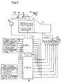
- an engine E connected to the automatic transmission A is equipped in its intake pipe 12 with a main throttle valve 13 and a sub-throttle valve 14 located upstream of the former.
- the main throttle valve 13 is so connected to an accelerator pedal 15 that it is controlled according to the depression of the accelerator pedal 15.
- the sub-throttle valve 14 is controlled by a motor 16.
- an engine electronic control unit (E-ECU) 17 for controlling the motor 16 to regulate the opening that sub-throttle valve 14 and for controlling the fuel injection rate and the ignition timing of the engine E.
- This electronic control unit 17 is composed mainly of a central processing unit (CPU), memory units (RAM and ROM) and an input/output interface and is fed as control data with a variety of signals including an engine (E/G) R.P.M. N, an amount Q of intake air, a temperature of intake air, a throttle opening, a vehicle speed, a temperature of engine water and a brake switch.
- CPU central processing unit
- RAM random access memory
- ROM read-only memory
- input/output interface input/output interface
- a hydraulic control unit 18 controls the shift, a lockup clutch, a line pressure and/or an engaging pressure of a predetermined frictional engagement means.
- the hydraulic control unit 18 is so constructed as to be electrically controlled and is equipped with: first to third shift solenoid valves S1 to S3 for executing the shift; a fourth solenoid valve S4 for controlling an engine braking state; a linear solenoid valve SLT for controlling the line pressure; a linear solenoid valve SLN for controlling an accumulator back pressure; and a linear solenoid valve SLU for controlling the engaging pressure of the lockup clutch or a predetermined frictional engagement means.
- T-ECU automatic transmission electronic control unit
- This electronic control unit 19 is composed mainly of a central processing unit (CPU), memory units (RAM and ROM) and an input/output interface and is fed as the control data with the throttle opening, the vehicle speed, the engine water temperature, the brake switch signal, a shift position signal, a pattern select switch signal, an overdrive switch signal, a signal coming from a C0 sensor for detecting the R.P.M. of a later-described clutch C0, a signal coming from a C2 sensor for detecting the R.P.M. of a later-described second clutch C2, an oil temperature of the automatic transmission and a signal of a manual shift switch.
- CPU central processing unit
- RAM random access memory
- ROM read-only memory
- an input/output interface is fed as the control data with the throttle opening, the vehicle speed, the engine water temperature, the brake switch signal, a shift position signal, a pattern select switch signal, an overdrive switch signal, a signal coming from a C0 sensor for
- the automatic transmission electronic control unit 19 and the engine electronic control unit 17 are connected with each other for data communications. Specifically, signals such as a signal of an amount (Q/N) of intake air per revolution are sent from the engine electronic control unit 17 to the automatic transmission electronic control unit 19, whereas signals such as a signal equivalent to a command signal for each solenoid valve or a signal for commanding a gear stage are sent from the automatic transmission electronic control unit 19 to the engine electronic control unit 17.
- the automatic transmission electronic control unit 19 decides the gear stage, the ON/OFF of the lockup clutch, or the regulated pressure level of the line pressure or the engaging pressure on the basis of the data inputted and the map stored in advance and outputs a command signal to a predetermined solenoid valve on the basis of the decision result to decide a failure or perform a control based on the decision.
- the engine electronic control unit 17 not only controls the fuel injection rate, the ignition timing and/or the opening of the sub-throttle valve 14 on the basis of the data inputted but also lowers the output torque temporarily by reducing the fuel injection rate at the shifting time of the automatic transmission A, by changing the ignition timing and/or by throttling the opening of the sub-throttle valve 14.
- Fig. 3 is a diagram showing one embodiment of the gear train of the automatic transmission A described above.
- the gear train is constructed to set five forward and one reverse gear stages.
- the automatic transmission A is constructed of a torque converter 20, an auxiliary transmission unit 21 and a main transmission unit 22.
- the torque converter 20 is equipped with a lockup clutch 23 which is interposed between a front cover 25 integrated with a pump impeller 24 and a member (or hub) 27 integrated with a turbine runner 26.
- the engine has its crankshaft (although both are not shown) connected to the front cover 25, and an input shaft 28 having the turbine runner 26 connected thereto is connected to a carrier 30 of an overdrive planetary gear mechanism 28 constituting the auxiliary transmission unit 21.
- the multi-disc clutch C0 Between the carrier 30 and a sun gear 31 of the planetary gear mechanism 29, there are interposed the multi-disc clutch C0 and a one-way clutch F0.
- this one-way clutch F0 is applied in case the sun gear 31 rotates forward (i.e., in the rotating direction of the input shaft 28) relative to the carrier 30.
- a multi-disc brake B0 for braking the rotation of the sun gear 31 selectively.
- a ring gear 32 acting as the output element of the auxiliary transmission unit 21 is connected to an intermediate shaft 33 acting as the input element of the main transmission unit 22.
- the planetary gear mechanism 29 rotates as a whole with the multi-disc clutch C0 or the one-way clutch F0 being applied, so that the intermediate shaft 33 rotates at the same speed as that of the input shaft 28, thus establishing a lower gear stage.
- the brake B0 being applied to stop the rotation of the sun gear 31, moreover, the ring gear 32 is accelerated with respect to the input shaft 28 to establish a higher gear stage.
- the main transmission unit 22 is equipped with three sets of planetary gear mechanisms 40, 50 and 60, which have their individual rotary elements connected, as follows. Specifically, a sun gear 41 of the first planetary mechanism 40 and a sun gear 51 of the second planetary mechanism 50 are integrally connected to each other. Moreover, a ring gear 43 of the first planetary mechanism 40, a carrier 52 of the second planetary mechanism 50 and a carrier 62 of the third planetary mechanism 60 are connected to one another, and an output shaft 65 is connected to the carrier 62 of the third planetary mechanism 60. In addition, the second planetary mechanism 50 has its ring gear 53 connected to a sun gear 61 of the third planetary mechanism 60.
- the gear train of this main transmission unit 22 can set one reverse and four forward gear stages and is composed of the following clutches and brakes for that settings. Of these, the clutches will be described at first.
- a first clutch C1 is interposed between a ring gear 53 of the second planetary mechanism 50 and the sun gear 61 of the third planetary mechanism 60, which are connected to each other, and the intermediate shaft 33.
- the second clutch C2 is interposed between the sun gear 41 of the first planetary mechanism 40 and the sun gear 51 of the second planetary mechanism 50, which are connected to each other, and the intermediate shaft 33.
- a first brake B1 is a band brake which is arranged to stop the rotations of the sun gears 41 and 51 of the first and second planetary mechanisms 40 and 50. Between these sun gears 41 and 51 (i.e., the common sun gear shaft) and a casing 66, there are arrayed in series a first one-way clutch F1 and a second brake B2 or a multi-disc brake. Of these, the first one-way clutch F1 is applied when the sun gears 41 and 51 are to rotate backward (of the rotating direction of the input shaft 28).
- a third brake B3 or a multi-disc brake is interposed between a carrier 42 of the first planetary mechanism 40 and the casing 66.
- a fourth brake B4 or a multi-disc brake for braking the rotation of the ring gear 63 and a second one-way clutch F2.
- this second one-way clutch F2 is applied when the ring gear 63 is to rotate backward.
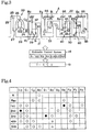
- the automatic transmission A thus far described can set five forward and one reverse gear stages by applying/releasing the individual clutches and brakes, as tabulated in the clutch/brake application chart of Fig. 4.
- symbols ⁇ indicate the applied state
- symbols ⁇ indicate the applied state to be taken at the time of engine braking
- symbols ⁇ indicate the applied or released state
- blanks indicate the released state.
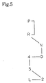
- the individual gear stages appearing in Fig. 4 are set according to the running ranges which are selected by operating the (not-shown) shift lever, and the positions of those running ranges to be selected by the shift lever are arrayed, as shown in Fig. 5.
- the array is made such that a parking (P) range position is followed by a reverse (R) range position and such that a neutral (N) range position is arranged subsequent to the R-range but oblique to the array of the P-range and the R-range.
- a drive (D) range position is arranged subsequent to the N-range in parallel with the aforementioned array direction of the P-range position and the R-range position.
- a 4th speed range position is subsequently arranged at a right angle with respect to the array direction of the N-range and the D-range.
- a 3rd speed range position is arranged subsequent to the 4th speed range position in parallel with the aforementioned array direction of the N-range and the D-range.
- a 2nd speed range position is arranged to have a relation similar to that which is taken by the N-range relative to the aforementioned R-range position.
- a low (L) range position is arranged to have a relation similar to that which is taken by the 4th speed range position relative to the D-range position.
- the D-range can establish the five forward gear stages; the 4th speed range can establish the four forward gear stages excepting the 5th speed or the overdrive gear stage; the 3rd speed range can establish the gear stages to the 3rd speed; the 2nd speed range can establish the gear stages to the 2nd speed; and the L-range can establish only the first speed.
- the shift lever is manually operated between the 3rd speed range position and the 2nd speed range position, there is established either an upshift from the 2nd speed to the 3rd speed or a downshift from the 3rd speed to the 2nd speed.
- reference numeral 70 designates a 1-2 shift valve
- numeral 71 designates a 2-3 shift valve
- numeral 72 designates a 3-4 shift valve.
- These shift valves 70, 71 and 72 have their individual ports opened to have communications at the individual gear stages, as respectively enumerated below themselves. Incidentally, the numerals indicate the individual gear stages.
- a brake port 74 to communicate with an input port 73 at the 1st and 2nd speeds is connected to the third brake B3 via an oil passage 75.
- This oil passage 75 is equipped with an orifice 76, and a damper valve 77 is connected between the orifice 76 and the third brake B3. The damper valve 77 sucks the oil pressure a little to perform its damping action in case the third brake B3 is abruptly fed with the line pressure.
- Reference numeral 78 designates a B-3 control valve for controlling the engaging pressure of the third brake B3 directly.
- the B-3 control valve 78 is equipped with a spool 79, a plunger 80 and a spring 81 sandwiched between the former two.
- An input port 82 to be controlled by the spool 79 is connected to the oil passage 75, and an output port 83 to be selectively caused to communicate with the input port 82 is connected to the third brake B3.
- the output port 3 is further connected to a feedback port 84 which is formed at the side of the leading end of the spool 79.
- a control port 88 formed at the side of the end portion of the plunger 80 is connected with the lockup clutch linear solenoid valve SLU.
- the B-3 control valve 78 has its regulated pressure level set by the elastic force of the spring 81 and the oil pressure fed to the port 85, so that its regulated pressure level rises to the higher value as the signal pressure fed to the control port 88 is the higher.
- reference numeral 89 appearing in Fig. 6 designates a 2-3 timing valve which is constructed to include: a spool 90 formed with one radially smaller land and two radially larger lands; a first plunger 91; a spring 92 sandwiched between the former two; and a second plunger 93 arranged at the side opposed to the first plunger 91 across the spool 90.
- This 2-3 timing valve 89 has its intermediate port 94 connected to an oil passage 95, which in turn is connected to such a port 96 of the 2-3 shift valve 71 as is caused to communicate with such the brake port 74 at a 3rd or higher speed gear stage.
- the oil passage 95 is branched in its midway and connected through an orifice to a port 97 which is opened between the aforementioned smaller-diameter land and one of the larger-diameter lands.
- a port 98 to be selectively caused to communicate with the port 94 at the intermediate portion is connected through an oil passage 99 with a solenoid relay valve 100.
- the lockup clutch linear solenoid valve SLU is connected to the port which is opened in the end portion of the first plunger 91, and the second brake B2 is connected through an orifice to the port which is opened in the end portion of the second plunger 93.
- the aforementioned oil passage 87 is provided for applying/releasing the oil pressure to and from the second brake B2 and is equipped in its midway with a smaller-diameter orifice 101 and an orifice 102 having a check ball. From this oil passage 87, there is branched an oil passage 103 which is equipped with a larger-diameter orifice 104 having a check ball to be opened when the second brake B2 is to be released.
- the oil passage 103 is connected with an orifice control valve 105, as will be described in the following.
- This orifice control valve 105 controls a rate of releasing the pressure from the second brake B2.
- This second brake B2 is connected to a port 107 which is so formed in an intermediate portion as can be opened or closed by a spool 106 of the orifice control valve 105.
- the aforementioned oil passage 103 is connected to a port 108 which is formed below that port 107, as shown.
- a port 109 is formed above the port 107 connected with the second brake B2, as shown, and is selectively caused to communicate with a drain port.
- a control port 112 formed at the end portion opposed to the spring for urging the spool 106 is connected to a port 114 of the 3-4 shift valve 72.
- This port 114 outputs a signal pressure of the third solenoid valve S3 at a 3rd or lower speed gear stage and a signal pressure of the fourth solenoid valve S4 at a 4th or higher speed gear stage.
- an oil passage 115 which is branched from the aforementioned oil passage 95 and which is selectively caused to communicate with the drain port.
- a port 116 for outputting a D-range pressure at a 2nd or lower speed gear stage is connected via an oil passage 118 to a port 117 which is opened in such a portion of the aforementioned 2-3 timing valve 89 as is arranged with the spring 92.
- a port 119 which is caused to communicate with the aforementioned oil passage 87 at a 3rd or lower, speed gear stage, is connected through an oil passage 120 with the solenoid relay valve 100.
- reference numeral 121 designates an accumulator for the second brake B2
- numeral 122 designates designates a C-0 exhaust valve
- numeral 123 designates an accumulator for the clutch C0.
- the C-0 exhaust valve 122 applies the clutch C0 so as to effect the engine braking only at the 2nd speed in the 2nd speed range.
- the engaging pressure to be fed to the third brake B3 at the time of setting the 2nd speed can be directly regulated by the B-3 control valve 78, and its regulated level can be varied by the linear solenoid valve SLU.
- the spool 106 of the orifice control valve 105 is in the position, as shown at the lefthand half in Fig. 6, the second brake B2 has communication with the oil passage 103 through that orifice control valve 105.
- the pressure can be released through the larger-diameter orifice 104 to control the rate of releasing the pressure from the second brake B2.
- the third brake B3 is applied at the 2nd speed, as can be seen from the clutch/brake application chart of Fig. 4. This engaging pressure is directly controlled by the B-3 control valve 78.
- Fig. 7 is a flow chart showing a routine for controlling the engaging pressure of the third brake B3 in the case of an upshift from the 1st speed to the 2nd speed.
- Step 1 it is decided whether or not a third timer T3 or a guard timer has counted up a predetermined time period ⁇ . Since not only this third timer T3 but also first and second timers T1 and T2, as will be described in the following, have their initial values set to "0", the first answer of Step 1 is "NO”, and the routine advances to Step 2.
- Step 2 it is decided whether or not an upshift of 1st to 2nd speeds is being executed. If the answer is "YES”, the third timer T3 is started (at Step 3), and the third solenoid valve S3 is turned OFF (at Step 4). This third solenoid valve S3 is normally closed to issue a signal pressure in its OFF state.
- the aforementioned orifice control valve 105 has its control port 112 fed with a signal pressure from the third solenoid valve S3 through the 3-4 shift valve 72 and the oil passage 113, so that its spool 106 is pushed down to the position, as shown at the righthand half in Fig. 6, to cause its port 109 to communicate with the drain port.
- This port 109 is connected to the port 111 of the B-3 control valve 78 so that the latter port 111 has communication with the drain.
- the B-3 control valve 78 comes into a state in which its pressure can be regulated.
- Step 5 it is decided whether or not a predetermined time period has elapsed from the upshift output from the 1st to 2nd speeds.
- the time period to be referred to for this decision is preset sufficient for ending the operation of the (not-shown) piston of the third brake B3. If the answer is "NO", a control of the standby of a low-pressure standby of the third brake B3 is executed at Step 6. This corresponds to the control corresponding to the function of the low-pressure standby means in the present invention. Specifically, this control lowers the regulated pressure level of the B-3 control valve 78 so that the engaging pressure to be fed to the third brake B3 may be set to a level as low as to move only the piston. In the hydraulic circuit shown in Fig.
- the signal pressure of the linear solenoid valve SLU pushes the spool 80 in the same direction as the spring 81 so that the signal pressure is set to a level lower than the elastic force of the spring 81 thereby to determine the regulated pressure level exclusively by the elastic force of the spring 81.
- no surge occurs because the oil pressure being fed is at a low level even if the piston of the third brake B3 reaches its stroke end during the control of that low-pressure standby.
- Step 7 If the answer of Step 5 is "YES" as a result that the control of the low-pressure standby is continued for the predetermined time period, the first and second timers T1 and T2 are started at Step 7. It is then decided (at Step 8) whether or not the inertial phase has been started.
- the first timer T1 prevents the gentle boosting control (i.e., the second gradual increase control) of the following engaging pressure (i.e., the pressure of B3) from being prematurely started on the basis of an erroneous detection of the inertial phase.
- the second timer T2 is a guard timer for determining the end period of the control (i.e., the first gradual increase control) for boosting the engaging pressure quickly.
- Step 8 can be executed on the basis of the three factors, i.e., the turbine R.P.M., the output shaft R.P.M. and the speed ratio.
- the operation of Step 8 corresponds to the means for detecting the start of the inertial phase.
- the first gradual increase control of the engaging pressure i.e., the pressure of B3
- This is a control for shortening the response delay of the shift as much as possible by feeding the oil pressure quickly to the third brake B3.
- the output signal pressure of the linear solenoid valve SLU is raised at first to such a level as can regulate the engaging pressure.
- the linear solenoid valve SLU is so controlled that the product of the signal pressure and the pressure receiving area of the plunger 88 may exceed the elastic force of the spring 81.
- the command signal from the electronic control unit 19 to the linear solenoid valve SLU has its value overshot temporarily so as to improve the responsiveness of the linear solenoid valve SLU.
- the signal pressure i.e., the regulated pressure level is raised to increase the engaging pressure to be fed to the third brake B3 at a considerably steep gradient.
- This boosting control is executed when the piston ends its operation, to establish little oil flow. Because of a small effective area of the B-3 control valve 78, moreover, there arises no surge.
- the rising gradient of the engaging pressure at this first gradual increase control may preferably be determined according to a running state, as dictated by the vehicle speed, the throttle opening or the input torque. For example, the boosting gradient is increased the steeper for the higher input torque or the larger throttle opening.
- Step 8 If the start of the inertial phase is detected during that first gradual increase control, the answer of Step 8 is "YES”. Then, the routine advances to Step 11, at which it is decided whether or not the first timer T1 has ended counting of a predetermined time period ⁇ ( ⁇ ⁇ ). If this answer is "NO”, the routine advances to Step 10 at which the aforementioned first gradual increase control is continued, because the first timer T1 prevents the first gradual increase control from being prematurely ended on the basis of the erroneous detection of the inertial phase.
- Step 12 the second gradual increase control of the engaging pressure (i.e., the pressure of B3) is executed (at Step 12).
- the rising gradient of the engaging pressure of this case may preferably be determined according to the running state dictated by the vehicle speed, the throttle opening or the input torque, as in the case of the first gradual increase control. For example, the pressure rising gradient is made the steeper for the higher input torque and the larger throttle opening.
- Step 2 the answer of Step 2 is "NO".
- This decision can be executed on the basis of the three, i.e., the turbine R.P.M. or the engine R.P.M., the output R.P.M. and the speed ratio.
- the routine advances to Step 13, the third solenoid valve S3 is turned ON.
- the third solenoid valve S3 is normally closed, as described before, to open the drain port, when it is turned ON, so that it does not output the signal pressure.
- Step 1 the routine advances directly to Step 13, at which the third solenoid valve S3 is turned ON to forcibly end the pressure regulation by the B-3 control valve 78. After this, the individual timers T1, T2 and T3 are cleared.
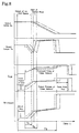
- Fig. 8 plots the changes of the output R.P.M. No., the output torque To, the command value and signal pressure of the linear solenoid valve SLU, and the engaging pressure of the third brake B3 in case the engaging pressure of the third brake B3 is controlled at the time of the upshift from the 1st to 2nd speeds.
- the normal states are indicated by solid lines; the higher signal pressures of the linear solenoid valve SLU are indicated by broken lines; and the lower signal pressures are indicated by single-dotted lines. Since the oil pressure to be fed to the third brake B3 is kept at the lower pressure till the end of the operation of the piston of the third brake B3, as is apparent from Fig. 8, and the engaging pressure is raised, so that its surge is not caused. Moreover, the aforementioned first gradual increase control is executed so that the responsiveness of the shift is improved.
- the present invention should not be limited to the foregoing embodiment but can also be applied to a shift control system for an automatic transmission other than not only that having the gear train shown in Fig. 3 and but also that having the hydraulic circuit shown in Fig. 6.
- the advantages to be obtained by the present invention According to the shift control system of the present invention, when the engaging pressure for applying the frictional engagement means is to be controlled directly by the pressure regulator valve, it is kept at such a low level at the beginning of its feed as can allow only the piston to move and is gradually raised after lapse of a predetermined time period. As a result, an excessive amount of oil is not fed even when the piston reaches its stroke end. Thus, the surge of the engaging pressure can be prevented to eliminate the deterioration of the shifting shock without fail.
- the pressure regulating valve is exemplified by a valve for setting the regulated pressure level in accordance with the elastic force of an elastic member such as a spring and the regulated pressure level
- the lower-pressure state at the beginning of the feed of the engaging pressure can be set by the elastic force of the elastic member so that the regulated pressure level can be easily set in a high control accuracy.
Applications Claiming Priority (3)
| Application Number | Priority Date | Filing Date | Title |
|---|---|---|---|
| JP5157990A JP3041163B2 (ja) | 1993-06-03 | 1993-06-03 | 自動変速機の変速制御装置 |
| JP157990/93 | 1993-06-03 | ||
| JP15799093 | 1993-06-03 |
Publications (3)
| Publication Number | Publication Date |
|---|---|
| EP0627580A2 true EP0627580A2 (fr) | 1994-12-07 |
| EP0627580A3 EP0627580A3 (fr) | 1996-05-15 |
| EP0627580B1 EP0627580B1 (fr) | 2001-10-17 |
Family
ID=15661838
Family Applications (1)
| Application Number | Title | Priority Date | Filing Date |
|---|---|---|---|
| EP94108454A Expired - Lifetime EP0627580B1 (fr) | 1993-06-03 | 1994-06-01 | Système de commande à changement de vitesses pour une transmission automatique |
Country Status (4)
| Country | Link |
|---|---|
| US (1) | US5527236A (fr) |
| EP (1) | EP0627580B1 (fr) |
| JP (1) | JP3041163B2 (fr) |
| DE (1) | DE69428625T2 (fr) |
Cited By (8)
| Publication number | Priority date | Publication date | Assignee | Title |
|---|---|---|---|---|
| DE19601555A1 (de) * | 1995-01-18 | 1996-07-25 | Mitsubishi Motors Corp | Gangänderungssteuerungsvorrichtung für ein Automatikgetriebe |
| EP0742391A1 (fr) * | 1995-05-12 | 1996-11-13 | Aisin Aw Co., Ltd. | Dispositif de commande pour une transmission automatique |
| EP0742388A2 (fr) * | 1995-05-12 | 1996-11-13 | Aisin Aw Co., Ltd. | Système de commmande pour une transmission automatique |
| EP0899483A2 (fr) * | 1997-08-29 | 1999-03-03 | Honda Giken Kogyo Kabushiki Kaisha | Dispositif de commande pour une transmission de véhicule actionnée hydrauliquement |
| EP0900957A2 (fr) * | 1997-09-04 | 1999-03-10 | Aisin Aw Co., Ltd. | Système de commande hydraulique pour transmission automatique |
| EP0833083A3 (fr) * | 1996-09-25 | 1999-07-07 | Honda Giken Kogyo Kabushiki Kaisha | Dispositif de commande pour transmission véhiculaire à commande hydraulique |
| EP1249642A1 (fr) * | 2001-04-09 | 2002-10-16 | Aisin Aw Co., Ltd. | Dispositif de commande pour transmission automatique de véhicule |
| WO2003029698A1 (fr) | 2001-09-28 | 2003-04-10 | Jatco Ltd | Dispositif de commande de changement de vitesses pour transmission automatique |
Families Citing this family (13)
| Publication number | Priority date | Publication date | Assignee | Title |
|---|---|---|---|---|
| GB2278654B (en) * | 1993-06-03 | 1997-11-19 | Toyota Motor Co Ltd | Shift control system for automatic transmission |
| KR100193254B1 (ko) * | 1994-11-09 | 1999-06-15 | 정몽규 | 차량용 자동변속기의 변속제어 시스템 |
| JPH08303575A (ja) * | 1995-05-10 | 1996-11-19 | Aisin Seiki Co Ltd | 自動変速機 |
| JP2828613B2 (ja) * | 1995-05-12 | 1998-11-25 | アイシン・エィ・ダブリュ株式会社 | 自動変速機の制御装置 |
| JP4028010B2 (ja) * | 1995-12-11 | 2007-12-26 | 株式会社デンソー | 車両用自動変速機制御装置 |
| KR970066220A (ko) * | 1996-03-13 | 1997-10-13 | 가나이 쯔도무 | 자동 변속기의 제어 장치 및 제어 방법 |
| JP3293455B2 (ja) * | 1996-04-04 | 2002-06-17 | アイシン・エィ・ダブリュ株式会社 | 自動変速機の制御装置 |
| JP3191683B2 (ja) * | 1996-06-11 | 2001-07-23 | アイシン・エィ・ダブリュ株式会社 | 自動変速機の変速制御装置 |
| US6085140A (en) * | 1997-12-05 | 2000-07-04 | Hyundai Motor Company | Shift control method and system for an automatic transmission |
| DE102005008010B4 (de) * | 2005-02-22 | 2022-01-27 | Zf Friedrichshafen Ag | Verfahren zur Erhöhung der Spontaneität bei Schaltungen eines Automatgetriebes oder eines automatisierten Schaltgetriebes |
| JP2006292007A (ja) * | 2005-04-07 | 2006-10-26 | Denso Corp | 自動変速機制御装置 |
| JP4929929B2 (ja) * | 2006-08-31 | 2012-05-09 | トヨタ自動車株式会社 | 車両の制御装置、制御方法、その制御方法をコンピュータに実行させるためのプログラムおよびプログラムを記録した記録媒体 |
| JP5153525B2 (ja) * | 2008-09-01 | 2013-02-27 | 本田技研工業株式会社 | クラッチ制御装置 |
Citations (9)
| Publication number | Priority date | Publication date | Assignee | Title |
|---|---|---|---|---|
| US4036083A (en) * | 1974-08-28 | 1977-07-19 | General Motors Corporation | Drive engagement pressure control by trimmer bias control |
| JPS63289359A (ja) * | 1987-05-21 | 1988-11-25 | Japan Autom Transmission Co Ltd | 自動変速機の変速時油圧制御装置 |
| DE3844039A1 (de) * | 1987-12-28 | 1989-07-13 | Mazda Motor | Hydrauliksteuerung fuer automatikgetriebe |
| US4855913A (en) * | 1987-05-29 | 1989-08-08 | J. I. Case Company | Electronic control system for powershift transmission |
| JPH02134457A (ja) * | 1988-11-15 | 1990-05-23 | Nissan Motor Co Ltd | 自動変速機の油圧緩和装置 |
| EP0385438A2 (fr) * | 1989-02-28 | 1990-09-05 | Nissan Motor Co., Ltd. | Réglage de la pression pour la transmission automatique d'un véhicule à moteur |
| JPH0366974A (ja) * | 1989-07-31 | 1991-03-22 | Komatsu Ltd | 流量検出弁 |
| EP0435378A2 (fr) * | 1989-12-26 | 1991-07-03 | General Motors Corporation | Méthode pour commander des changement de vitesse dans une transmission automatique |
| US5125295A (en) * | 1990-10-19 | 1992-06-30 | Toyota Jidosha Kabushiki Kaisha | Method for speed stage shifting of automatic transmission with incipient back pressure control |
Family Cites Families (14)
| Publication number | Priority date | Publication date | Assignee | Title |
|---|---|---|---|---|
| JPS533028B2 (fr) * | 1971-10-02 | 1978-02-02 | ||
| JPS5536611A (en) * | 1978-09-05 | 1980-03-14 | Nissan Motor Co Ltd | Throttle fail safe valve for automatic speed change gear |
| JPS5877956A (ja) * | 1981-10-30 | 1983-05-11 | Aisin Warner Ltd | 自動変速機の油圧調整装置 |
| JPS6118527A (ja) * | 1984-07-06 | 1986-01-27 | Toyota Motor Corp | 自動変速機車両の内燃機関制御装置 |
| WO1986004969A1 (fr) * | 1985-02-19 | 1986-08-28 | Kabushiki Kaisha Komatsu Seisakusho | Procede de commande d'un embrayage de changement de vitesse dans une transmission |
| JPS62194060A (ja) * | 1986-02-17 | 1987-08-26 | Toyota Motor Corp | 自動変速機の変速制御装置 |
| JP2618624B2 (ja) * | 1986-05-08 | 1997-06-11 | 三菱自動車工業 株式会社 | 車両用自動変速機の制御装置 |
| JP2505755B2 (ja) * | 1986-07-10 | 1996-06-12 | 日産自動車株式会社 | 自動変速機の液圧制御装置 |
| JPS6383442A (ja) * | 1986-09-24 | 1988-04-14 | Aisin Seiki Co Ltd | 自動変速機の変速制御装置 |
| JP2805062B2 (ja) * | 1987-02-19 | 1998-09-30 | トヨタ自動車株式会社 | 自動変速機の変速制御装置 |
| JPH0633817B2 (ja) * | 1988-03-03 | 1994-05-02 | 本田技研工業株式会社 | 自動変速機の変速制御方法 |
| JPH0246358A (ja) * | 1988-08-06 | 1990-02-15 | Honda Motor Co Ltd | 自動変速機の変速制御装置 |
| JP2913486B2 (ja) * | 1990-04-10 | 1999-06-28 | アイシン精機株式会社 | 自動変速機の油圧制御装置 |
| US5179875A (en) * | 1991-03-22 | 1993-01-19 | Ford Motor Company | Turbine speed controller for an automatic transmission |
-
1993
- 1993-06-03 JP JP5157990A patent/JP3041163B2/ja not_active Expired - Lifetime
-
1994
- 1994-06-01 DE DE69428625T patent/DE69428625T2/de not_active Expired - Lifetime
- 1994-06-01 EP EP94108454A patent/EP0627580B1/fr not_active Expired - Lifetime
- 1994-06-03 US US08/253,777 patent/US5527236A/en not_active Expired - Lifetime
Patent Citations (9)
| Publication number | Priority date | Publication date | Assignee | Title |
|---|---|---|---|---|
| US4036083A (en) * | 1974-08-28 | 1977-07-19 | General Motors Corporation | Drive engagement pressure control by trimmer bias control |
| JPS63289359A (ja) * | 1987-05-21 | 1988-11-25 | Japan Autom Transmission Co Ltd | 自動変速機の変速時油圧制御装置 |
| US4855913A (en) * | 1987-05-29 | 1989-08-08 | J. I. Case Company | Electronic control system for powershift transmission |
| DE3844039A1 (de) * | 1987-12-28 | 1989-07-13 | Mazda Motor | Hydrauliksteuerung fuer automatikgetriebe |
| JPH02134457A (ja) * | 1988-11-15 | 1990-05-23 | Nissan Motor Co Ltd | 自動変速機の油圧緩和装置 |
| EP0385438A2 (fr) * | 1989-02-28 | 1990-09-05 | Nissan Motor Co., Ltd. | Réglage de la pression pour la transmission automatique d'un véhicule à moteur |
| JPH0366974A (ja) * | 1989-07-31 | 1991-03-22 | Komatsu Ltd | 流量検出弁 |
| EP0435378A2 (fr) * | 1989-12-26 | 1991-07-03 | General Motors Corporation | Méthode pour commander des changement de vitesse dans une transmission automatique |
| US5125295A (en) * | 1990-10-19 | 1992-06-30 | Toyota Jidosha Kabushiki Kaisha | Method for speed stage shifting of automatic transmission with incipient back pressure control |
Non-Patent Citations (3)
| Title |
|---|
| PATENT ABSTRACTS OF JAPAN vol. 013, no. 100 (M-805), 9 March 1989 & JP-A-63 289359 (JAPAN AUTOM TRANSMISSION CO LTD), 25 November 1988, * |
| PATENT ABSTRACTS OF JAPAN vol. 014, no. 373 (M-1009), 13 August 1990 & JP-A-02 134457 (NISSAN MOTOR CO LTD), 23 May 1990, * |
| PATENT ABSTRACTS OF JAPAN vol. 015, no. 225 (M-1122), 10 June 1991 & JP-A-03 066974 (KOMATSU LTD), 22 March 1991, * |
Cited By (19)
| Publication number | Priority date | Publication date | Assignee | Title |
|---|---|---|---|---|
| DE19601555A1 (de) * | 1995-01-18 | 1996-07-25 | Mitsubishi Motors Corp | Gangänderungssteuerungsvorrichtung für ein Automatikgetriebe |
| DE19601555B4 (de) * | 1995-01-18 | 2004-07-15 | Mitsubishi Jidosha Kogyo K.K. | Gangänderungssteuerungsvorrichtung für ein Automatikgetriebe |
| EP0742391A1 (fr) * | 1995-05-12 | 1996-11-13 | Aisin Aw Co., Ltd. | Dispositif de commande pour une transmission automatique |
| EP0742388A2 (fr) * | 1995-05-12 | 1996-11-13 | Aisin Aw Co., Ltd. | Système de commmande pour une transmission automatique |
| EP0742388A3 (fr) * | 1995-05-12 | 1996-11-20 | Aisin Aw Co., Ltd. | Système de commmande pour une transmission automatique |
| US5741201A (en) * | 1995-05-12 | 1998-04-21 | Aisin Aw Co., Ltd. | Control system for automatic transmission |
| US5788603A (en) * | 1995-05-12 | 1998-08-04 | Aisin Aw Co., Ltd. | Control system for automatic transmission |
| EP0833083A3 (fr) * | 1996-09-25 | 1999-07-07 | Honda Giken Kogyo Kabushiki Kaisha | Dispositif de commande pour transmission véhiculaire à commande hydraulique |
| EP0899483A3 (fr) * | 1997-08-29 | 1999-07-14 | Honda Giken Kogyo Kabushiki Kaisha | Dispositif de commande pour une transmission de véhicule actionnée hydrauliquement |
| US6024663A (en) * | 1997-08-29 | 2000-02-15 | Honda Giken Kogyo Kabushiki Kaisha | Control apparatus for hydraulically operated vehicular transmission |
| CN1103887C (zh) * | 1997-08-29 | 2003-03-26 | 本田技研工业株式会社 | 用于液压操纵的车辆变速箱的控制设备 |
| EP0899483A2 (fr) * | 1997-08-29 | 1999-03-03 | Honda Giken Kogyo Kabushiki Kaisha | Dispositif de commande pour une transmission de véhicule actionnée hydrauliquement |
| EP0900957A2 (fr) * | 1997-09-04 | 1999-03-10 | Aisin Aw Co., Ltd. | Système de commande hydraulique pour transmission automatique |
| EP0900957A3 (fr) * | 1997-09-04 | 2000-07-19 | Aisin Aw Co., Ltd. | Système de commande hydraulique pour transmission automatique |
| EP1249642A1 (fr) * | 2001-04-09 | 2002-10-16 | Aisin Aw Co., Ltd. | Dispositif de commande pour transmission automatique de véhicule |
| US6712735B2 (en) | 2001-04-09 | 2004-03-30 | Aisin Aw Co., Ltd. | Control apparatus for automatic transmission |
| WO2003029698A1 (fr) | 2001-09-28 | 2003-04-10 | Jatco Ltd | Dispositif de commande de changement de vitesses pour transmission automatique |
| EP1431624A1 (fr) * | 2001-09-28 | 2004-06-23 | JATCO Ltd | Dispositif de commande de changement de vitesses pour transmission automatique |
| EP1431624A4 (fr) * | 2001-09-28 | 2007-10-03 | Jatco Ltd | Dispositif de commande de changement de vitesses pour transmission automatique |
Also Published As
| Publication number | Publication date |
|---|---|
| EP0627580B1 (fr) | 2001-10-17 |
| US5527236A (en) | 1996-06-18 |
| DE69428625T2 (de) | 2002-07-11 |
| EP0627580A3 (fr) | 1996-05-15 |
| DE69428625D1 (de) | 2001-11-22 |
| JPH06341524A (ja) | 1994-12-13 |
| JP3041163B2 (ja) | 2000-05-15 |
Similar Documents
| Publication | Publication Date | Title |
|---|---|---|
| US5527236A (en) | Shift control system for automatic transmission | |
| EP0476832B1 (fr) | Système de commande électronique pour transmissions à étages multiples incluant une commande de pression du système | |
| US5816979A (en) | Vehicle control apparatus capable of selective slip control of lock-up clutch during deceleration and automatic shift-down of transmission during downhill road running | |
| US5957800A (en) | Shift control system for automatic transmission | |
| US5947856A (en) | Control system for automatic transmission, including coordinated frictional engagement element release control | |
| EP0627336B1 (fr) | Système de commande à changement de vitesse pour une transmission automatique | |
| EP0479418A2 (fr) | Commande de circuit électronique pour une transmission à roues arrières à engrenage multiple | |
| WO1997000391A1 (fr) | Dispositif de commande pour transmission automatique | |
| US5865709A (en) | Apparatus for controlling vehicle lock-up clutch, wherein engine output is reduced upon releasing action of lock-up clutch | |
| US5569117A (en) | Slip control apparatus for motor vehicle lock-up clutch | |
| JPH0559298B2 (fr) | ||
| US5672138A (en) | Control system for automatic transmission | |
| US5924957A (en) | Speed change control system for automatic transmission | |
| US5634869A (en) | Shift control system for automatic transmission | |
| US6754572B2 (en) | Hydraulic pressure control apparatus of automatic transmission | |
| US5707317A (en) | Control system for automatic transmission | |
| US5113725A (en) | Hydraulic control device of automatic transmission more smooth in low coast upshifting under under-D manual shift range | |
| US5842951A (en) | Speed change control system for automatic transmission | |
| US5899831A (en) | Automatic transmission upshift control apparatus | |
| JPH0972409A (ja) | 自動変速機の変速制御装置 | |
| JPH06341525A (ja) | 自動変速機の油圧制御装置 | |
| JP3620229B2 (ja) | 自動変速機の制御装置 | |
| JP3498476B2 (ja) | 油圧制御弁 | |
| JPH08270780A (ja) | 自動変速機の制御装置 | |
| JPH02150561A (ja) | 電子制御自動変速装置 |
Legal Events
| Date | Code | Title | Description |
|---|---|---|---|
| PUAI | Public reference made under article 153(3) epc to a published international application that has entered the european phase |
Free format text: ORIGINAL CODE: 0009012 |
|
| AK | Designated contracting states |
Kind code of ref document: A2 Designated state(s): DE GB |
|
| PUAL | Search report despatched |
Free format text: ORIGINAL CODE: 0009013 |
|
| AK | Designated contracting states |
Kind code of ref document: A3 Designated state(s): DE GB |
|
| 17P | Request for examination filed |
Effective date: 19961031 |
|
| 17Q | First examination report despatched |
Effective date: 19980213 |
|
| GRAG | Despatch of communication of intention to grant |
Free format text: ORIGINAL CODE: EPIDOS AGRA |
|
| GRAG | Despatch of communication of intention to grant |
Free format text: ORIGINAL CODE: EPIDOS AGRA |
|
| GRAG | Despatch of communication of intention to grant |
Free format text: ORIGINAL CODE: EPIDOS AGRA |
|
| GRAH | Despatch of communication of intention to grant a patent |
Free format text: ORIGINAL CODE: EPIDOS IGRA |
|
| GRAH | Despatch of communication of intention to grant a patent |
Free format text: ORIGINAL CODE: EPIDOS IGRA |
|
| GRAA | (expected) grant |
Free format text: ORIGINAL CODE: 0009210 |
|
| AK | Designated contracting states |
Kind code of ref document: B1 Designated state(s): DE GB |
|
| REF | Corresponds to: |
Ref document number: 69428625 Country of ref document: DE Date of ref document: 20011122 |
|
| REG | Reference to a national code |
Ref country code: GB Ref legal event code: IF02 |
|
| PLBE | No opposition filed within time limit |
Free format text: ORIGINAL CODE: 0009261 |
|
| STAA | Information on the status of an ep patent application or granted ep patent |
Free format text: STATUS: NO OPPOSITION FILED WITHIN TIME LIMIT |
|
| 26N | No opposition filed | ||
| PGFP | Annual fee paid to national office [announced via postgrant information from national office to epo] |
Ref country code: GB Payment date: 20130529 Year of fee payment: 20 Ref country code: DE Payment date: 20130529 Year of fee payment: 20 |
|
| REG | Reference to a national code |
Ref country code: DE Ref legal event code: R071 Ref document number: 69428625 Country of ref document: DE |
|
| REG | Reference to a national code |
Ref country code: GB Ref legal event code: PE20 Expiry date: 20140531 |
|
| PG25 | Lapsed in a contracting state [announced via postgrant information from national office to epo] |
Ref country code: GB Free format text: LAPSE BECAUSE OF EXPIRATION OF PROTECTION Effective date: 20140531 |
|
| PG25 | Lapsed in a contracting state [announced via postgrant information from national office to epo] |
Ref country code: DE Free format text: LAPSE BECAUSE OF EXPIRATION OF PROTECTION Effective date: 20140603 |