EP0623459B1 - Procédé et dispositif pour améliorer l'uniformité de chauffage d'adhésif pour la fabrication de carton ondulé - Google Patents
Procédé et dispositif pour améliorer l'uniformité de chauffage d'adhésif pour la fabrication de carton ondulé Download PDFInfo
- Publication number
- EP0623459B1 EP0623459B1 EP94303279A EP94303279A EP0623459B1 EP 0623459 B1 EP0623459 B1 EP 0623459B1 EP 94303279 A EP94303279 A EP 94303279A EP 94303279 A EP94303279 A EP 94303279A EP 0623459 B1 EP0623459 B1 EP 0623459B1
- Authority
- EP
- European Patent Office
- Prior art keywords
- contact
- conveyor belt
- back side
- heating
- corrugated paperboard
- Prior art date
- Legal status (The legal status is an assumption and is not a legal conclusion. Google has not performed a legal analysis and makes no representation as to the accuracy of the status listed.)
- Expired - Lifetime
Links
Images


Classifications
-
- B—PERFORMING OPERATIONS; TRANSPORTING
- B31—MAKING ARTICLES OF PAPER, CARDBOARD OR MATERIAL WORKED IN A MANNER ANALOGOUS TO PAPER; WORKING PAPER, CARDBOARD OR MATERIAL WORKED IN A MANNER ANALOGOUS TO PAPER
- B31F—MECHANICAL WORKING OR DEFORMATION OF PAPER, CARDBOARD OR MATERIAL WORKED IN A MANNER ANALOGOUS TO PAPER
- B31F1/00—Mechanical deformation without removing material, e.g. in combination with laminating
- B31F1/20—Corrugating; Corrugating combined with laminating to other layers
- B31F1/24—Making webs in which the channel of each corrugation is transverse to the web feed
- B31F1/26—Making webs in which the channel of each corrugation is transverse to the web feed by interengaging toothed cylinders cylinder constructions
- B31F1/28—Making webs in which the channel of each corrugation is transverse to the web feed by interengaging toothed cylinders cylinder constructions combined with uniting the corrugated webs to flat webs ; Making double-faced corrugated cardboard
- B31F1/2831—Control
- B31F1/284—Warp prevention
-
- B—PERFORMING OPERATIONS; TRANSPORTING
- B31—MAKING ARTICLES OF PAPER, CARDBOARD OR MATERIAL WORKED IN A MANNER ANALOGOUS TO PAPER; WORKING PAPER, CARDBOARD OR MATERIAL WORKED IN A MANNER ANALOGOUS TO PAPER
- B31F—MECHANICAL WORKING OR DEFORMATION OF PAPER, CARDBOARD OR MATERIAL WORKED IN A MANNER ANALOGOUS TO PAPER
- B31F1/00—Mechanical deformation without removing material, e.g. in combination with laminating
- B31F1/20—Corrugating; Corrugating combined with laminating to other layers
- B31F1/24—Making webs in which the channel of each corrugation is transverse to the web feed
- B31F1/26—Making webs in which the channel of each corrugation is transverse to the web feed by interengaging toothed cylinders cylinder constructions
- B31F1/28—Making webs in which the channel of each corrugation is transverse to the web feed by interengaging toothed cylinders cylinder constructions combined with uniting the corrugated webs to flat webs ; Making double-faced corrugated cardboard
- B31F1/2845—Details, e.g. provisions for drying, moistening, pressing
- B31F1/2877—Pressing means for bringing facer sheet and corrugated webs into contact or keeping them in contact, e.g. rolls, belts
- B31F1/2881—Pressing means for bringing facer sheet and corrugated webs into contact or keeping them in contact, e.g. rolls, belts for bringing a second facer sheet into contact with an already single faced corrugated web
-
- Y—GENERAL TAGGING OF NEW TECHNOLOGICAL DEVELOPMENTS; GENERAL TAGGING OF CROSS-SECTIONAL TECHNOLOGIES SPANNING OVER SEVERAL SECTIONS OF THE IPC; TECHNICAL SUBJECTS COVERED BY FORMER USPC CROSS-REFERENCE ART COLLECTIONS [XRACs] AND DIGESTS
- Y10—TECHNICAL SUBJECTS COVERED BY FORMER USPC
- Y10T—TECHNICAL SUBJECTS COVERED BY FORMER US CLASSIFICATION
- Y10T156/00—Adhesive bonding and miscellaneous chemical manufacture
- Y10T156/10—Methods of surface bonding and/or assembly therefor
- Y10T156/1002—Methods of surface bonding and/or assembly therefor with permanent bending or reshaping or surface deformation of self sustaining lamina
- Y10T156/1007—Running or continuous length work
- Y10T156/1016—Transverse corrugating
-
- Y—GENERAL TAGGING OF NEW TECHNOLOGICAL DEVELOPMENTS; GENERAL TAGGING OF CROSS-SECTIONAL TECHNOLOGIES SPANNING OVER SEVERAL SECTIONS OF THE IPC; TECHNICAL SUBJECTS COVERED BY FORMER USPC CROSS-REFERENCE ART COLLECTIONS [XRACs] AND DIGESTS
- Y10—TECHNICAL SUBJECTS COVERED BY FORMER USPC
- Y10T—TECHNICAL SUBJECTS COVERED BY FORMER US CLASSIFICATION
- Y10T156/00—Adhesive bonding and miscellaneous chemical manufacture
- Y10T156/10—Methods of surface bonding and/or assembly therefor
- Y10T156/1002—Methods of surface bonding and/or assembly therefor with permanent bending or reshaping or surface deformation of self sustaining lamina
- Y10T156/1025—Methods of surface bonding and/or assembly therefor with permanent bending or reshaping or surface deformation of self sustaining lamina to form undulated to corrugated sheet and securing to base with parts of shaped areas out of contact
Definitions
- This invention relates to the field of corrugated paperboard manufacturing, and more particularly, to an apparatus and method for setting the adhesive in the manufacturing of corrugated paperboard.
- Corrugated paperboard is widely used as a material for fabricating containers and for other packaging applications. Corrugated paperboard is strong, lightweight, relatively inexpensive, and may be recycled. Conventional corrugated paperboard is constructed of two opposing liners and an intervening fluted sheet secured together using an adhesive. The adhesive is typically a starch-based adhesive applied as a liquid. Accordingly, heat is transferred to the adhesive to dry or set the adhesive during manufacturing of the corrugated paperboard.
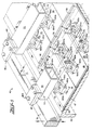
- a conventional so-called “double facer” 20 for setting adhesive is schematically illustrated.
- the double facer joins a "single faced" corrugated paperboard sheet, including a single liner and the fluted paper, together with a second liner and heats the sheet to dry or set the adhesive.
- This heating is typically achieved by passing the corrugated paperboard over a series of steam heating chests from left to right as shown in the illustrated double facer 20 .
- the heating chests are typically grouped together in heating sections 21a-21d. More particularly, the corrugated paperboard is advanced over the series of steam heated chests by an endless conveyor belt 23 and its associated drive 24 to engage the sheet and advance the sheet in contact with the underlying heating chests.
- a lower traction belt 26 assists in advancing the sheet through the double facer.
- a series of transversely extending rolls 25 are carried by side rails 24 (FIG. 1) and provide a downward or backing pressure on the back side of the conveyor belt 23 .
- the rolls 25 of a conventional double facer are intended to provide a backing force to facilitate contact between the advancing corrugated sheet 27 and the underlying heating surfaces 28 of the heating chests 22 . See also, for example, U.S. Patent No. 4,316,755 to Flaum et al. and U.S. Patent No. 3,981,758 to Thayer et al.
- the upper heating surface 28 of the heating chest 22 is substantially planar. Accordingly, the sheet 27 is evenly pressed across the heating surface by the liner backing rolls 25 , and uniform heating and setting of the adhesive may be obtained.
- the heating chests 22 have a tendency to bow inward at their centers as a result of temperature differences in the walls of the heating chest. The bowing is typically more severe in an upstream heating chest 22 since the cooler corrugated paperboard produces a larger temperature differential in the upstream heating chest.
- the thermally induced bow may cause a loss of contact at the center of the heating surface 28 as illustrated by the gap 30 . Accordingly, heat is not properly transferred into the adjacent portion of the corrugated paperboard sheet, resulting in scrap or an inferior product, such as a sheet having blisters. Moreover, the edge portions of the sheet 27 must support the full weight of the rolls 25 as indicated by the downward directed arrows which, in turn, typically results in crushed edge portions of the sheet. The crushed edge portions also produce an inferior product or scrap.
- Another drawback of backing rolls is that a relatively large number of heating chests 22 must be used to ensure that all portions of the sheet, particularly the center portion, obtain sufficient heat to set the adhesive.
- the additional heating chests 22 have ambient energy losses; hence, the overall energy efficiency of the process is reduced.
- the additional heating chests fail to address the problem of edge crush of the corrugated paperboard sheet also caused by bowing of the heating chests.
- each roll has a padded covering or an enlarged medial portion to attempt to conform to the bowed heating chest surface.
- DE-2 108 378 discloses an apparatus for forming corrugated paper in which a flat paper facing sheet is glued to a traveling corrugated paper sheet.
- the apparatus is provided with an endless travelling belt the lower strand of which rests on an upper facing sheet. Resting on this lower strand of the belt is a plurality of waiting rollers arranged in rows extending lengthwise on the belt, so as to roll along the surface of the belt. Above each row of rollers there is a beam to which the rollers are pivotally connected.
- the beams are adjustable vertically in order to adjust the pressure on the rollers against the belt. The beams are prevented from moving lengthwise.
- GB-2 233 935B discloses a heat transfer system particularly, though not exclusively, for assisting the bonding of a continuous liner sheet to a single faced board in a corrugating machine.
- a single faced board, after gluing the corrugated tips is brought together with the liner and conveyed across a series of hot plates, in a known manner.
- the invention consists of a series of vessels containing a liquid or gas which are arranged in a longitudinal series above the conveyed board to press same uniformly in contact, in order to compensate for fluctuations in the surface shape of the hot plates.
- an apparatus for setting an adhesive in corrugated paperboard during the manufacturing thereof comprising a series of elongate heating chests positioned in side-by-side relation and defining a series of laterally extending heating surfaces, and a conveyor belt positioned opposite said series of heating surfaces for advancing a corrugated paperboard sheet longitudinally along a predetermined path of travel over said heating surfaces, characterized by a plurality of contact assemblies associated with a backside of said conveyor belt for slidably contacting and pressing upon the backside of said conveyor belt to urge the advancing corrugated paperboard sheet into substantially uniform contact with said laterally extending heating surfaces, each of said contact assemblies comprising a laterally extending frame positioned adjacent the back side of said conveyor belt, a plurality of contact shoes carried by said frame and arranged in side-by-side relation, each of said contact shoes having a contact surface for Bias means, such as provided by respective compressed coil springs, urges the contact surfaces or the contact shoes against the conveyor belt.
- Bias means such as provided by respective compressed coil springs
- the series of individually biased contact shoes provides a substantially uniform backing pressure applied across the respective heating surface, even in the presence of any thermally induced bowing.
- the series of contact shoes applies a predetermined uniform pressure to the sheet to thereby overcome the edge crush tendency of the prior art roll-based systems.
- heat is more efficiently transferred to the advancing sheet by the present invention, fewer heating chests may be used, or, alternately, the apparatus may be operated at a higher speed.
- Each contact assembly also preferably includes shoe mounting means for mounting each of the contact shoes to the frame so that each is independently movable along a path of travel into and outward from the heating surfaces.
- the shoe mounting means is preferably provided by front and rear pairs of arms and respective pivot shafts for pivotally securing opposing ends of each arm to the frame and each shoe, respectively.
- each of the contact shoes is also preferably pivotable with respect to its imaginary longitudinal centerline.
- an enlarged or elongated opening is preferably provided in an end of the arms cooperating with the respective pivot shafts.
- lateral pivotal movement over a desired range is also provided by the shoe mounting means.
- Contact assembly mounting means is preferably provided for mounting the plurality of contact assemblies so that each contact assembly is associated with a respective laterally extending heating surface.
- the mounting means preferably mounts the contact assemblies to the opposing side rails of the apparatus. Accordingly, substantially complete coverage of each of the heating surfaces may be achieved.
- the contact assembly mounting means also preferably arranges adjacent assemblies in laterally staggered relation to laterally offset longitudinally extending gaps between the contact shoes of the adjacent assemblies.
- Each of the contact assemblies also preferably includes stop means operatively connected between the frame and each of the contact shoes for setting a minimum clearance between the contact shoe and the heating surface.
- the stop means defines a stopping point along the path of travel into the back side of said conveyor belt.
- the stop means may be selectively adjusted to provide backing pressure for a sheet having a minimum predetermined thickness while preventing each contact shoe from fully pressing against adjacent portions of the back side of the conveyor belt when the apparatus is operated without the corrugated paperboard sheet in place adjacent a respective portion of said conveyor belt, such as during start-up of the apparatus or when manufacturing a sheet having a width less than the full width of the conveyor belt.
- Each contact shoe is preferably provided by a generally rectangular plate having an upturned leading end to facilitate sliding contact with the conveyor belt.
- the upturned end prevents snagging on the moving conveyor belt.
- All of the plates also have substantially uniform dimensions to simplify construction and maintenance of the contact assemblies.
- a contact assembly apparatus adapted to be positioned on an apparatus of the type for setting an adhesive in corrugated paperboard during the manufacturing thereof, the setting apparatus comprising heating means for defining a heating surface for advancing a corrugated paperboard sheet along a predetermined path of travel over the heating surface, said contact assembly apparatus comprising a frame adapted to be positioned adjacent the back side of the conveyor belt and extending laterally thereacross; a plurality of contact shoes carried by said frame and arranged in side-by-side relation, each of said contact shoes having a contact surface adapted for slidably contacting the back side of the conveyor belt, and biasing means operatively connected between said frame and each of said contact shoes and adapted for urging the contact surface thereof against the back side of the conveyor belt.
- the step of slidably contacting the back side of the conveyor belt includes the steps of providing a series of contact assemblies associated with the back side of the conveyor belt as described above, and biasing each of the contact shoes for urging the contact surface of the contact shoe against the back side of the conveyor belt.
- the method also preferably includes the step of setting a minimum clearance between each contact shoe and the heating surface to thereby prevent each contact shoe from fully pressing against adjacent portions of the back side of the conveyor belt when the apparatus is operated without the corrugated paperboard sheet in place adjacent a respective portion of the conveyor belt.
- the minimum clearance is also less than a corresponding minimum thickness of a corrugated paperboard sheet to be heated so that the contact shoe is biased even for the minimum thickness sheet.
- the contact shoes preferably include a generally rectangular plate. Accordingly, the method preferably further includes the step of arranging the plates in laterally spaced apart relation defining longitudinally extending gaps between adjacent plates, and mounting adjacent ones of the contact assemblies in laterally staggered relation to laterally offset the longitudinally extending gaps in adjacent assemblies.
- Another method aspect according to the invention includes the steps of sensing a temperature of the corrugated paperboard sheet downstream from the heating surfaces, and lowering or lifting predetermined ones of the contact assemblies so that the contact shoes thereof are positioned to transfer more or less heat to thereby maintain a predetermined exit temperature for the sheet.
- corrugated paperboard is constructed of two opposing liners and an intervening fluted sheet secured together using an adhesive.
- the adhesive is typically a starch-based adhesive applied as a liquid that must be dried or set during manufacturing of the corrugated paperboard.
- the illustrated embodiment of the apparatus 40 of the present invention includes a series of elongate steam heating chests 42 positioned in side-by-side relation to define a series of laterally extending heating surfaces 48 for heating a corrugated paperboard sheet 47 to thereby dry or set the adhesive.
- the heating chests 42 are of a conventional type heated to about 350°F by a steam supply, as would be readily appreciated by those skilled in the art.
- the heating chests 42 raise the temperature of the corrugated sheet 47 from its preheated temperature of about 120°F at the entry of the apparatus 40 , to about 180-200°F at the exit end of the apparatus 40 .
- Each of the chests 42 is elongate and typically about 18 or 24 inches in the longitudinal direction and about 90 to 100 inches in the lateral direction as would be readily understood by those skilled in the art.
- Conventional roll-based machines typically required about 18 to 28 such heating chests, while only about 7 to 16 such chests 42 may be needed for a typical installation using the present invention.
- the number of heating chests depends upon desired speed of operation and other factors as would be readily understood by those skilled in the art.
- the apparatus 40 also includes an endless conveyor belt 43 of a conventional type as would also be readily appreciated by those skilled in the art.
- the conveyor belt 43 includes a front or working side for engaging a corrugated paperboard sheet 47 and advancing the sheet along a predetermined longitudinal path of travel over the series of heating chests 42 .
- the conveyor belt 43 requires backing pressure to ensure that the relatively fast moving sheet 47 sufficiently contacts the heating surfaces 48 to absorb heat and set the adhesive.
- a heating chest 42 has a tendency to develop an inward bow or deflection in a medial portion of its upper heating surface 48 during operation of the apparatus 40 .
- This thermally induced deflection is caused by the difference in temperature between the various wall portions of the heating chest 42 as hot steam is passed through the chest, while the relatively cool corrugated paperboard sheet 47 cools the heating surface 48 of the chest because of the heat transferred from the chest to the sheet.
- the bow is typically more pronounced in the upstream heating chests 42 because of the relatively cooler temperature of the sheet at that area.
- the apparatus 40 of the present invention includes sliding contact means associated with a back side of the conveyor belt 43 for slidably contacting and pressing upon the back side of the conveyor belt to urge the advancing corrugated paperboard sheet 47 into substantially uniform contact with the laterally extending heating surfaces 48 despite any thermally induced deflection or bowing thereof.
- the sliding contact means is provided by a plurality of contact assemblies 50 .
- the contact assemblies 50 according to the present invention may be installed on new lines or, alternately, the contact assemblies may be readily substituted for existing rolls in retrofit applications.
- Each contact assembly 50 preferably includes a laterally extending frame 52 positioned adjacent the back side of the conveyor belt 43 .
- a plurality of contact shoes 54 are carried by the frame 52 and arranged in side-by-side relation. As illustrated, each of the contact shoes 54 has a contact surface for slidably contacting the back side of the conveyor belt 43 .
- Each of the contact shoes 54 preferably includes a generally rectangular steel plate 56 of mild steel defining the contact surface. The mild steel is readily formed, durable, and yet will not prematurely wear the conveyor belt 43 . Another suitable material for the plates 56 may be a ceramic which will give even longer wear.
- each of the generally rectangular plates 56 preferably have uniform dimensions and each of the plates 56 preferably has a length corresponding to the underlying heating chest 42 , which, as stated above, is typically about 18 or 24 inches in the longitudinal direction. A slight gap may also be formed between longitudinally adjacent plates 56 .
- the contact shoes 54 of the present invention provide a backing pressure over substantially the full extent of the heating surface 48 of the heating chest 42 , in sharp contrast to prior roll-based systems which provided only spaced apart lineal contact with the conveyor belt.
- each of the generally rectangular plates 56 includes an upturned leading edge 58 to facilitate sliding contact with the conveyor belt 43 .
- the upturned leading edge 58 prevents snagging of the conveyor belt 43 , particularly at the seam area of the belt, not shown.
- the radius of curvature of the upturned end 58 may be about the same as for a conventional backing roll.
- the contact assembly 50 further includes biasing means operatively connected between the frame 50 and each of the contact shoes 54 for biasing the contact surface thereof against the back side of the conveyor belt 43 .
- the biasing means is provided by respective coil springs 55 having a predetermined spring constant and a predetermined amount of initial compression.
- the amount of initial compression for each spring 55 may be set by a predetermined height of an enlarged diameter area of a spacer pad 59 .
- the spacer pad 59 has a lower enlarged diameter area and an upper reduced diameter area defining a shoulder therebetween. The lower end of the coil spring 55 rests upon the shoulder and the upper end of the spring is captured by the head of a bolt 57 as shown best in FIG. 6.
- the initial compression of the spring 55 and the spring constant establish the initial bias force applied to the contact shoe 54 .
- a coil spring 55 having a free length of about 2.25 inches and a 130 lbs./in. spring constant may be set to have an initial length of about 2 inches.
- the amount of initial compression, and hence the initial biasing force may be set based upon a desired pressure for the contact surface of each contact shoe 54 as would be readily understood by those skilled in the art.
- the desired pressure may also be based upon a measurement of current draw on a motor driving the conveyor belt 43 , so that the motor is operated in a desired range.
- Other biasing means and approaches for setting the initial bias of a coil spring 55 are also contemplated by the present invention.
- the shoe mounting means permits each of the contact shoes 54 to be independently movable along a predetermined path of travel generally normal to the heating surfaces 48 .
- each contact shoe 54 may move independently in an up and down motion to accommodate bowing of the underlying heating surface 48 .
- the up and down movement also accommodates variations in the belt thickness, particularly to accommodate the belt seam, and variations in the thickness of the corrugated paperboard sheet 47 being manufactured.
- the shoe mounting means includes a front pair of arms 62 and a rear pair of arms 64 .
- Each of the pairs of arms 62 , 64 are connected at a lower end by lower front and rear pivot shafts, or spigots, 65a , 66a , respectively.
- the pivot shafts 65a , 66a are provided by turned end portions of respective front and rear lower mounting blocks 67a , 68a secured to the rectangular plate 56 .
- Each of the pairs of mounting arms 62 , 64 is connected at an upper end by upper front and rear pivot shafts, or spigots 65b , 66b , respectively.
- These upper pivot shafts 65b , 66b are preferably provided by reduced diameter end portions of respective shafts carried by a parallel pair of upper mounting blocks 70 secured to the frame 52 .
- stop means being operatively connected between the frame 52 and each of the contact shoes 54 for defining a predetermined minimum clearance between each of the contact surfaces and a respective portion of the heating surface 48 . Accordingly, pressure is relieved on the back side of the conveyor belt 43 when the apparatus 40 is operated and the belt is driven without the corrugated paperboard sheet 47 being located underlying the respective portion of the conveyor belt, to thus reduce unnecessary wear on the belt.
- the corrugated paperboard sheet 47 may not be present when the apparatus 40 is initially started, or at the edges of the heating surfaces 48 as when a narrow width sheet is being manufactured.
- the clearance is set so that backing pressure is provided for a minimum thickness 47 sheet.
- the stop means is preferably provided by angled upper portions of the front arms 62 and uppermost pivot shafts, or spigots, 65c .
- the pivot shafts 65c are preferably provided by turned end portions of a stop block 74 wherein the position of the stop block 74 relative to the frame 52 is also determined by an adjustable bolt 72 connected to the frame.
- the adjustable bolt 72 is set for the minimum thickness of the corrugated paperboard sheet 47 to be manufactured while still providing a clearance for when no sheet is present.
- Other arrangements for stop means are also contemplated by the present invention as will be appreciated by those skilled in the art.
- FIGS. 8 and 9 another feature of the shoe mounting means according to the invention is explained.
- Enlarged or elongated openings 77 at the lower end of the front pair of arms 62 and enlarged openings 78 at the rear pair of arms 64 cooperate with their respective pivot shafts 65a , 66a to permit the generally rectangular plate 56 of the contact shoe 54 to pivot with respect to an imaginary longitudinal centerline of the contact surface. Accordingly, the contact shoes 54 may laterally pivot to more readily conform to any bowing of the heating surfaces 48 .
- the apparatus 40 preferably includes a pair of opposing longitudinally extending side rails 78 .
- the contact assemblies 50 may thus be readily secured to the rails 78 by spacers 82 and mounting plates 81a , 81b having slightly different lengths. Accordingly, the longitudinally extending gaps between adjacent plates 56 may be staggered or offset so that a continuous line of no backing force is not presented to the back side of the conveyor belt 43 .
- the contact assemblies 50 are mounted so that each is laterally staggered or offset from adjacent ones by alternating the mounting plates 81a, 81b for adjacent assemblies 50 .
- All or predetermined ones of the contact assemblies 50 may include lifting means for selectively positioning a contact assembly between an operating position or a raised position.
- the operating position the contact surfaces of the contact shoes 54 are positioned against the conveyor belt 43 .
- the raised position the frame 52 and, accordingly, the contact shoes 54 are raised so that no backing pressure is applied to the back side of the conveyor belt 43 .
- a pair of pneumatically operable actuators or pistons 86 may be connected to a contact assembly frame 52 at the respective opposing ends thereof to raise or lower the contact assembly 50 responsive to a pressure source 90 and suitable control valve 91 .
- a lower stop position may be set by stop bolts 93 .
- the lifting means may be connected to all or predetermined ones of the contact assemblies 50 to permit control of the amount of heat imparted to the advancing corrugated paperboard sheet 47 to thereby maintain the temperature of the sheet within a predetermined range.
- the method preferably uses an apparatus 40 of the type including a plurality of heating chests 42 arranged in side-by-side relation defining a series of laterally extending heating surfaces 48 , and a conveyor belt 43 positioned opposite the series of heating surfaces.
- the method includes the steps of: driving the conveyor belt 43 to advance a corrugated paperboard sheet 47 longitudinally along a predetermined path of travel over the heating surfaces 48 , and slidably contacting and pressing upon a back side of the driven conveyor belt so as to urge the advancing corrugated paperboard sheet 47 into substantially uniform contact with the laterally extending heating surfaces despite any thermally induced bowing or deflection thereof and without crushing the sheet.
- the step of slidably contacting the back side of the conveyor belt 43 preferably includes the steps of providing a series of contact assemblies 50 associated with the back side of the conveyor belt as described above, and biasing each of the contact shoes 54 for urging the contact surface of the contact shoe against the back side of the conveyor belt 43 .
- the method also preferably includes the step of setting a minimum clearance between each contact shoe 54 and the heating surface 48 to thereby prevent each contact shoe from fully pressing against adjacent portions of the back side of the conveyor belt when the apparatus 40 is operated without the corrugated paperboard sheet 47 in place adjacent a respective portion of the conveyor belt, while still also imparting a bias force to a sheet having a predetermined minimum thickness.
- Each of the contact shoes 54 preferably includes a generally rectangular plate 56 . Accordingly, the method preferably further includes the step of arranging the plates 56 in laterally spaced apart relation defining longitudinally extending gaps between adjacent plates, and mounting adjacent contact assemblies 50 in laterally staggered relation to laterally offset the longitudinally extending gaps in the adjacent assemblies.
- Another method aspect according to the invention includes the steps of sensing a temperature of the corrugated paperboard sheet 47 downstream from the heating surfaces 48 , and lifting or lowering predetermined ones of the contact assemblies 50 so that the backing pressure is controlled to maintain the temperature of the sheet 47 within a predetermined range.
- a typical desired temperature for the sheet 47 at the exist of the apparatus 40 may preferably be in the range of about 180 to 200°F for a typical adhesive.
Claims (16)
- Appareil de prise d'adhésif appliqué au carton ondulé lors de son élaboration, ledit appareil comportant:une série de caissons de chauffe (42) en longueur disposés en rapport côte à côte et définissant une série de surfaces chauffantes (48) allongées en sens latéral; etun transporteur à bande (43) situé face à ladite série de surfaces chauffantes pour avancer une feuille de carton ondulé (47) en sens longitudinal sur un parcours prédéfini au dessus desdites surfaces chauffantes (48) caractérisé en ce qu'une pluralité d'ensembles de contact (50) associés à un côté arrière de ladite bande transporteuse (43) pour contacter en glissement et appuyer sur le côté arrière de ladite bande transporteuse afin d'accélérer l'avance de la feuille de carton ondulé (47) en contact essentiellement uniforme avec lesdites surfaces chauffantes en extension (48) chacun desdits ensembles de contact comportant:un cadre en extension latérale (52) situé adjacent au côté arrière de ladite bande transporteuse (43),une pluralité de patins de contact (54) portés par ledit cadre en rapport côte à côte, chacun desdits patins de contact (54) ayant une surface de contact (56) permettant le contact en glissement du côté arrière de la bande transporteuse, etdes moyens de dérive (55) en liaison fonctionnelle entre ledit cadre (52) et chacun desdits patins de contact (54) pour la mise en biais de leur surface de contact (56) contre le côté arrière de ladite bande transporteuse.
- Appareil selon la revendication 1, comportant une paire de rails (78) en extension longitudinale le long des côtés opposés desdites surfaces chauffantes (48), et lesdits moyens de pose d'ensemble de contact (81,82) pour monter une pluralité d'ensembles de contact (50), de façon telle que chaque ensemble de contact (50) est associé avec une surface chauffante (48) en extension latérale.
- Appareil selon la revendication 1 ou la revendication 2, dont ladite pluralité de patins de contact (54) comporte des surfaces respectives de contact (56) comportant des plaques généralement s de dimensions essentiellement uniformes, et dont chaque plaque généralement est de longueur correspondant essentiellement à une longueur d'une dite surface chauffante respective (48).
- Appareil selon la revendication 3, dont chacune des plaques généralement s prévoit un bord d'attaque en extension latérale retroussée pour faciliter le contact en glissement avec ladite bande transporteuse.
- Appareil selon la revendication 3 ou la revendication 4, dont les plaques généralement s de chaque ensemble de contact (50) sont disposées en rapport espacé latéral définissant des écarts en extension longitudinale entre les plaques avoisinantes, et dont lesdits moyens de pose d'ensemble de contact (81,82) comportent des moyens pour la pose des ensembles de contact adjacents (50) en rapport de quinconce latérale pour assurer le décalage latéral des écarts en extension longitudinale d'ensembles adjacents.
- Appareil d'ensembles de contact adapté pour la pose sur un appareil du modèle de prise d'adhésif sur le carton ondulé lors de son élaboration, l'appareil de prise comportant des moyens chauffants (42) pour définir une surface chauffante (48) et une bande transporteuse (43) située face à la surface de chauffe (48) pour avancer une feuille de carton ondulé (47¦) le long d'un parcours prédéterminé sur la surface chauffante (48) dudit appareil à ensemble de contact comportant:un cadre (52) adapté pour être situé adjacent au côté arrière de ladite bande transporteuse (43) et en extension latérale en travers,une pluralité de patins de contact (54) portés par ledit cadre et disposés en rapport côte à côte, chacun desdits patins de contact (54) ayant une surface de contact (56) adaptée au contact en glissement du côté arrière de la bande transporteuse (43), etdes moyens de dérive (55) en liaison fonctionnelle entre ledit cadre (52) et chacun desdits patins de contact (54) adapté pour en avancer la surface de contact (56) contre le côté arrière de la bande transporteuse (43).
- Appareil selon l'une ou l'autre des revendications précédentes, comportant des moyens de pose de patins (42-70) pour la pose de chaque patin de contact (54) sur ledit cadre (52) de façon telle que chaque surface de contact (56) est adaptée pour être mobile de façon indépendante le long d'un parcours prédéterminé généralement perpendiculaire à la surface chauffante (48).
- Appareil selon la revendication 7, suivant laquelle lesdits moyens de pose de patins (62-70) comportent une pluralité de bras (62,64) et d'axes respectifs de pivotement (65a,65b; 66a,66b) leur étant en coopération pour le blocage par pivotement de chaque bras sur ledit cadre (52) et chacun des patins de contact (54) respectivement.
- Appareil selon la revendication 8, suivant laquelle chacun desdits bras (62,64) prévoit une ouverture élargie (77,78) en une de leurs extrémités pour coopérer avec des axes respectifs de pivotement (65a,65b; 66a,66b) permettant le mouvement pivotant de chacune desdites surfaces de contact (56) autour de son axe longitudinal imaginaire.
- Appareil selon l'une ou l'autre des revendications précédentes, comportant des moyens de butée en liaison fonctionnelle entre ledit cadre (52) et chacun desdits patins de contact (54) étant adapté pour définir un écart minimum entre chacune desdites surfaces de contact et une portion respective de la surface chauffante afin que la pression d'appui est apportée à une feuille de carton ondulé (47) ayant une épaisseur minimum prédéterminée et pour ainsi soulager la pression sur le côté arrière de ladite bande transporteuse (43) lorsque l'appareil fonctionne sans feuille de carton ondulé en position adjacente à une portion respective de ladite bande transporteuse.
- Appareil selon l'une ou l'autre des revendications précédentes, selon lequel des moyens de déviation en biais (55) comportent des ressorts respectifs en liaison fonctionnelle entre chacun desdits patins de contact(54) et ledit cadre (52).
- Appareil selon l'une ou l'autre des revendications précédentes, comportant des moyens de levage (86) raccordés audit cadre (52) et adaptés pour le positionnement sélectif dudit cadre (52) entre une position fonctionnelle. suivant laquelle les surfaces de contact (56) desdits patins de contact (54) sont adaptées pour venir en contact avec le côté arrière de la bande transporteuse (43) et une position surélevée, suivant laquelle les surfaces de contact (56) sont adaptées pour être écartées par rapport au côté arrière de la bande transporteuse (43).
- Méthode de chauffe uniforme de carton ondulé lors de son élaboration pour la prise de l'adhésif sur le carton ondulé avec un appareil du modèle comportant une pluralité de caissons chauffants disposés en rapport côte à côte et définissant une série de surfaces chauffantes en extension latérale, et une bande transporteuse positionnée face à la série de surfaces chauffantes, la méthode comportant les phases suivantes:le fonctionnement de la bande transporteuse (43) pour avancer longitudinalement une feuille de carton ondulé (47) le long d'un parcours prédéterminé sur les surfaces chauffantes (48); etle contact en glissement et l'appui sur un côté arrière de la bande transporteuse (43) pour accélérer l'avance de la feuille de carton ondulé (47) en contact essentiellement uniforme avec les surfaces chauffantes adjacentes en extension latérale (48) nonobstant leur déflexion thermique induite éventuelle, ladite phase de contact de glissement du coté arrière de la bande transporteuse (43) comportant les phases suivantes:l'apport d'une série d'ensembles de contact associés avec le côté arrière de la bande transporteuse, chaque ensemble de contacts comportant une pluralité de patins de contact disposés en rapport côte à côte en extension latérale en travers de la bande transporteuse, chacun des patins de contact ayant une surface pour le contact de glissement avec le côté arrière de la bande transporteuse etla déviation en biais de chaque patin de contact pour accélérer l'avance de la surface de contact contre le côté arrière de la bande transporteuse.
- Méthode selon la revendication 13, comportant en outre la phase de:soulagement de la pression contre le côté arrière de ladite bande transporteuse (43) lorsque l'appareil fonctionne sans la feuille de carton ondulé (47) en position adjacente à une portion respective de la bande transporteuse (43).
- Méthode selon la revendication 13 ou la revendication 14, suivant laquelle l'appareil comporte une pluralité de patins de contact (54) dont chacun comporte généralement une plaque (58), la méthode prévoyant la phase d'ajustage des plaques généralement rectangulaires en rapport latéral espacé définissant des écarts en sens longitudinal s'allongeant entre les plaques adjacentes (56), et comportant en outre la phase de pose des ensembles de contacts adjacents (50) en quinconce latérale assurant le décalage latérale des écarts en extension longitudinale des ensembles adjacents (50).
- Méthode selon l'une ou l'autre des revendications 13 à 15, comportant les phases de captage de la température de la feuille de carton ondulé (47) en aval des surfaces chauffantes (48) et de la descente ou du levage de certains ensembles prédéterminés de contact (50), pour le transfert supérieur ou inférieur de chaleur respectivement, de telle façon à maintenir la température de la feuille de carton ondulé (47) dans une fourchette prédéterminée.
Applications Claiming Priority (2)
| Application Number | Priority Date | Filing Date | Title |
|---|---|---|---|
| US58912 | 1993-05-06 | ||
| US08/058,912 US5456783A (en) | 1993-05-06 | 1993-05-06 | Apparatus and method for enhancing heating uniformity for setting adhesive in corrugated paperboard manufacturing |
Publications (3)
| Publication Number | Publication Date |
|---|---|
| EP0623459A2 EP0623459A2 (fr) | 1994-11-09 |
| EP0623459A3 EP0623459A3 (fr) | 1995-04-19 |
| EP0623459B1 true EP0623459B1 (fr) | 1997-08-06 |
Family
ID=22019684
Family Applications (1)
| Application Number | Title | Priority Date | Filing Date |
|---|---|---|---|
| EP94303279A Expired - Lifetime EP0623459B1 (fr) | 1993-05-06 | 1994-05-06 | Procédé et dispositif pour améliorer l'uniformité de chauffage d'adhésif pour la fabrication de carton ondulé |
Country Status (6)
| Country | Link |
|---|---|
| US (1) | US5456783A (fr) |
| EP (1) | EP0623459B1 (fr) |
| JP (1) | JP2685406B2 (fr) |
| AT (1) | ATE156418T1 (fr) |
| DE (2) | DE623459T1 (fr) |
| ES (1) | ES2108381T3 (fr) |
Families Citing this family (30)
| Publication number | Priority date | Publication date | Assignee | Title |
|---|---|---|---|---|
| US5611267A (en) * | 1993-09-22 | 1997-03-18 | Corrugated Gear & Services, Inc. | Apparatus and method for applying variable pressure to a surface in corrugated paperboard manufacturing |
| US5526739A (en) * | 1993-09-22 | 1996-06-18 | Corrugated Gear & Services Inc. | Apparatus for applying variable pressure to a surface |
| DE4420726A1 (de) * | 1994-06-16 | 1995-12-21 | Bhs Corr Masch & Anlagenbau | Maschine zur Herstellung einer mindestens einseitig kaschierten Wellpappebahn |
| DE19506778A1 (de) * | 1995-02-27 | 1996-08-29 | Bhs Corr Masch & Anlagenbau | Verfahren zum Herstellen von Wellpappe |
| GB2299543B (en) * | 1995-04-06 | 1997-07-16 | Scm Container Mach Ltd | A heat transfer system |
| US5863377A (en) * | 1995-04-07 | 1999-01-26 | Modular Concepts, Inc. | Laminate-forming apparatus |
| EP0739710B1 (fr) * | 1995-04-24 | 1998-11-25 | PETERS MASCHINENFABRIK GmbH | Presse-lisse dans une machine de fabrication de carton ondulé |
| US5746010A (en) * | 1995-06-26 | 1998-05-05 | Marquip, Inc. | Web holddown and drive for corrugator double backer |
| US5561918A (en) * | 1995-06-26 | 1996-10-08 | Marquip, Inc. | Web holdown and drive for corrugator double backer |
| DE19603015A1 (de) * | 1996-01-17 | 1997-07-24 | Europa Carton Ag | Andrückleiste |
| US5788803A (en) * | 1996-10-16 | 1998-08-04 | Interfic, Inc. | Corrugated paperboard manufacturing apparatus with controllable preheating |
| US5837974A (en) * | 1996-10-16 | 1998-11-17 | Interfic, Inc. | Corrugated paperboard manufacturing apparatus with board profile monitoring and related methods |
| US5902502A (en) * | 1996-10-16 | 1999-05-11 | Interfic, Inc. | Corrugated paperboard manufacturing apparatus and related methods |
| US5847362A (en) * | 1996-10-16 | 1998-12-08 | Interfic, Inc. | Corrugated paperboard manufacturing apparatus providing controllable heat and related methods |
| JP3524698B2 (ja) * | 1996-10-31 | 2004-05-10 | 三菱重工業株式会社 | 加圧装置付き貼合シート材製造システム |
| US5732622A (en) * | 1997-01-24 | 1998-03-31 | Corrugated Gear And Services | Machine for manugacturing corrugated board |
| JPH10244607A (ja) * | 1997-03-07 | 1998-09-14 | Mitsubishi Heavy Ind Ltd | ダブルフェーサ |
| DE19710210A1 (de) * | 1997-03-12 | 1998-09-17 | Meyer Herbert Gmbh Co Kg | Vorrichtung zum Verkleben flächiger Materialien |
| US6110095A (en) * | 1997-04-18 | 2000-08-29 | United Container Machinery Inc. | Apparatus for heating corrugated paperboard |
| WO1999017924A1 (fr) * | 1997-10-03 | 1999-04-15 | United Container Machinery, Inc. | Procede et appareil permettant d'engager une feuille continue |
| AU1315399A (en) * | 1997-11-10 | 1999-05-31 | Interfic, Inc. | Corrugated paperboard manufacturing apparatus and method for enhancing heat transfer to an advancing corrugated paperboard sheet |
| US5890301A (en) * | 1997-11-11 | 1999-04-06 | Marquip, Inc. | Thread-up apparatus for a corrugator double backer |
| DE19811858A1 (de) * | 1998-03-18 | 1999-09-23 | Bhs Corr Masch & Anlagenbau | Heizvorrichtung für eine Wellpappenanlage |
| DE19815863A1 (de) * | 1998-04-08 | 1999-10-14 | Peters W Maschf | Druckplatten-Anordnung zum Zusammenfügen einer Mehrzahl von jeweils wenigstens eine Glattbahn und/oder wenigstens eine Wellbahn umfassenden Materialbahnen zu einer Wellpappebahn |
| US6390963B1 (en) | 1998-11-30 | 2002-05-21 | Corrugated Gear & Services, Inc. | Corrugated board manufacturing apparatus including a preheater section with a variable heat transfer system and a hotplate section with a passive hold-down mechanisim |
| US6717193B2 (en) | 2001-10-09 | 2004-04-06 | Koninklijke Philips Electronics N.V. | Metal-insulator-metal (MIM) capacitor structure and methods of fabricating same |
| DE10245264A1 (de) * | 2002-09-27 | 2004-04-01 | Bhs Corrugated Maschinen- Und Anlagenbau Gmbh | Wellpappe-Anlage |
| EP1491325B1 (fr) * | 2003-06-27 | 2006-08-02 | FOSBER S.p.A. | Dispositif pour joindre des feuilles en carton pour former de carton ondulé |
| US7722742B2 (en) * | 2006-12-06 | 2010-05-25 | Voith Patent Gmbh | Corrugator belt |
| US9952160B2 (en) | 2014-04-04 | 2018-04-24 | Packaging Corporation Of America | System and method for determining an impact of manufacturing processes on the caliper of a sheet material |
Family Cites Families (25)
| Publication number | Priority date | Publication date | Assignee | Title |
|---|---|---|---|---|
| FR350144A (fr) * | 1904-08-30 | 1905-10-25 | Fr De L Ondulium Soc | Machine pour la fabrication de papier, carton, etc., en feuilles collées superposées |
| US2252585A (en) * | 1939-03-20 | 1941-08-12 | Gair Company Canada Ltd | Means for drying corrugated board |
| US2554968A (en) * | 1939-03-29 | 1951-05-29 | Robert M Thompson | Continuous pressure separating device operating in multiple stages |
| US2300982A (en) * | 1941-05-29 | 1942-11-03 | Slagboom Louis | Decating machine |
| US2508216A (en) * | 1947-08-08 | 1950-05-16 | Bonds | Apparatus for the preparation of printing blocks |
| US2941573A (en) * | 1958-03-28 | 1960-06-21 | Robert T Cassady | Method of and apparatus for regulating corrugating machines |
| US3217425A (en) * | 1962-09-25 | 1965-11-16 | West Virginia Pulp & Paper Co | Corrugator |
| US3319353A (en) * | 1964-03-30 | 1967-05-16 | Niwa Machinery Company Ltd | Pressing and drying devices for corrugated board manufacturing equipment |
| US3468734A (en) * | 1966-02-07 | 1969-09-23 | S & S Corrugated Paper Mach | Method and apparatus for producing corrugated board |
| DE1957270B1 (de) * | 1969-11-14 | 1971-04-22 | Eickhoff Geb | Vorrichtung zum Herstellen von Wellpappe mit doppelseitig glatter Deckbahn |
| DE2108378C3 (de) | 1971-02-22 | 1973-10-18 | Eickhoff-Universal Wellpappenmaschinen Gmbh, 4630 Bochum | Vorrichtung zum Herstellen von Wellpappe mit doppelseitig glatter Bahn |
| US3981758A (en) * | 1974-11-04 | 1976-09-21 | Koppers Company, Inc. | Process control system for corrugators |
| CA1035333A (fr) * | 1975-02-13 | 1978-07-25 | John J. Grevich | Fermeture en bande pour sacs |
| US4042446A (en) * | 1975-08-14 | 1977-08-16 | Henry Simon Limited | Corrugated board-making machinery |
| US4126508A (en) * | 1976-09-13 | 1978-11-21 | Boise Cascade Corporation | Apparatus for forming multi-flute-layer corrugated board |
| US4268341A (en) * | 1978-03-15 | 1981-05-19 | S&S Corrugated Paper Machinery Co. Inc. | Zero waste order change system for a corrugator |
| DE2851007C3 (de) * | 1978-11-24 | 1982-02-04 | BHS-Bayerische Berg-, Hütten- und Salzwerke AG, 8000 München | Vorrichtung zur Herstellung einer wenigstens einseitig deckbelegten Wellpappe |
| US4316755A (en) * | 1979-03-20 | 1982-02-23 | S&S Corrugated Paper Machinery Co., Inc. | Adhesive metering device for corrugating processes |
| DE2935373C2 (de) * | 1979-09-01 | 1985-08-08 | Lindauer Dornier Gmbh, 8990 Lindau | Vorrichtung zur Wärmebehandlung von flachen, auf gasdurchlässigen Transportbändern aufliegenden Warenbahnen |
| FI76856C (fi) * | 1987-02-05 | 1988-12-12 | Tampella Oy Ab | Foerfarande och anordning foer torkning av en pappersbana eller liknande. |
| JPH01169321U (fr) * | 1988-05-19 | 1989-11-29 | ||
| US5256240A (en) * | 1989-07-18 | 1993-10-26 | Simon Container Machinery Limited | Corrugating machine with a flexible vessel pressure applying means |
| GB8916373D0 (en) * | 1989-07-18 | 1989-09-06 | Simon Container Mach Ltd | A heat transfer system |
| CH684688A5 (fr) * | 1990-11-14 | 1994-11-30 | Bobst Sa | Dispositif d'assemblage pour élément en bande composé de couches superposées et encollées pour une machine de production de carton ondulé. |
| US5129980A (en) * | 1991-05-24 | 1992-07-14 | Interfic Developments, Inc. | Apparatus for applying glue to the flute tips of a single-faced corrugated paperboard sheet |
-
1993
- 1993-05-06 US US08/058,912 patent/US5456783A/en not_active Expired - Lifetime
- 1993-12-28 JP JP5336511A patent/JP2685406B2/ja not_active Expired - Lifetime
-
1994
- 1994-05-06 EP EP94303279A patent/EP0623459B1/fr not_active Expired - Lifetime
- 1994-05-06 DE DE0623459T patent/DE623459T1/de active Pending
- 1994-05-06 ES ES94303279T patent/ES2108381T3/es not_active Expired - Lifetime
- 1994-05-06 AT AT94303279T patent/ATE156418T1/de not_active IP Right Cessation
- 1994-05-06 DE DE69404733T patent/DE69404733T2/de not_active Expired - Fee Related
Also Published As
| Publication number | Publication date |
|---|---|
| DE623459T1 (de) | 1996-11-28 |
| EP0623459A3 (fr) | 1995-04-19 |
| EP0623459A2 (fr) | 1994-11-09 |
| ES2108381T3 (es) | 1997-12-16 |
| US5456783A (en) | 1995-10-10 |
| DE69404733D1 (de) | 1997-09-11 |
| JP2685406B2 (ja) | 1997-12-03 |
| DE69404733T2 (de) | 1998-03-26 |
| ATE156418T1 (de) | 1997-08-15 |
| JPH06328596A (ja) | 1994-11-29 |
Similar Documents
| Publication | Publication Date | Title |
|---|---|---|
| EP0623459B1 (fr) | Procédé et dispositif pour améliorer l'uniformité de chauffage d'adhésif pour la fabrication de carton ondulé | |
| US5837974A (en) | Corrugated paperboard manufacturing apparatus with board profile monitoring and related methods | |
| CA2055403C (fr) | Dispositif utilise pour l'assemblage de pieces en bandes formees de couches superposees et collees, concu pour etre utilise avec un appareil de parement a double face sur | |
| US5630903A (en) | Machine for the manufacture of a single-face lined web of corrugated board | |
| US5993587A (en) | Double facer with threading means | |
| US4038130A (en) | Corrugating machine having self-adjusting web guides | |
| EP1491325B1 (fr) | Dispositif pour joindre des feuilles en carton pour former de carton ondulé | |
| KR100465564B1 (ko) | 연속 동작 프레스 | |
| EP3042757B1 (fr) | Dispositif et procédé pour empêcher le gauchissement d'une feuille de carton ondulé à double-face et appareil de fabrication pour une feuille de carton ondulé à double-face | |
| US5902502A (en) | Corrugated paperboard manufacturing apparatus and related methods | |
| US5788803A (en) | Corrugated paperboard manufacturing apparatus with controllable preheating | |
| US5847362A (en) | Corrugated paperboard manufacturing apparatus providing controllable heat and related methods | |
| EP1452303B1 (fr) | Dispositif et procédé pour la fabrication d'un carton ondulé à simple face | |
| EP0839642B1 (fr) | Système, équipée avec un dispositif de pressage, pour la fabrication d'un matériau en forme de feuilles collés | |
| US5578160A (en) | Heat transfer control system for a double backer | |
| US5044269A (en) | Continuously working press | |
| US5224367A (en) | Method for the treatment of the steel belts of a double belt press | |
| GB2281922A (en) | Apparatus for producing single-faced corrugated board sheets | |
| US5439544A (en) | No-crush roll system and method in a double backer | |
| JPH10305499A (ja) | ダブルフェーサ | |
| JP2678354B2 (ja) | ダブルフェーサー | |
| JPH11300859A (ja) | コルゲートマシンのダブルフェーサ | |
| WO1999024249A1 (fr) | Appareil de production de carton ondule et procede d'amelioration du transfert thermique vers une feuille de carton ondule avançante | |
| SE505007C2 (sv) | Kontinuerlig press för framställning av spån-,fiber-, plast- eller plywoodskivor eller liknande |
Legal Events
| Date | Code | Title | Description |
|---|---|---|---|
| PUAI | Public reference made under article 153(3) epc to a published international application that has entered the european phase |
Free format text: ORIGINAL CODE: 0009012 |
|
| AK | Designated contracting states |
Kind code of ref document: A2 Designated state(s): AT BE CH DE DK ES FR GB GR IE IT LI LU MC NL PT SE |
|
| PUAL | Search report despatched |
Free format text: ORIGINAL CODE: 0009013 |
|
| AK | Designated contracting states |
Kind code of ref document: A3 Designated state(s): AT BE CH DE DK ES FR GB GR IE IT LI LU MC NL PT SE |
|
| 17P | Request for examination filed |
Effective date: 19950619 |
|
| 17Q | First examination report despatched |
Effective date: 19960613 |
|
| GRAG | Despatch of communication of intention to grant |
Free format text: ORIGINAL CODE: EPIDOS AGRA |
|
| DET | De: translation of patent claims | ||
| GRAH | Despatch of communication of intention to grant a patent |
Free format text: ORIGINAL CODE: EPIDOS IGRA |
|
| GRAH | Despatch of communication of intention to grant a patent |
Free format text: ORIGINAL CODE: EPIDOS IGRA |
|
| GRAA | (expected) grant |
Free format text: ORIGINAL CODE: 0009210 |
|
| AK | Designated contracting states |
Kind code of ref document: B1 Designated state(s): AT BE CH DE DK ES FR GB GR IE IT LI LU MC NL PT SE |
|
| PG25 | Lapsed in a contracting state [announced via postgrant information from national office to epo] |
Ref country code: NL Free format text: LAPSE BECAUSE OF FAILURE TO SUBMIT A TRANSLATION OF THE DESCRIPTION OR TO PAY THE FEE WITHIN THE PRESCRIBED TIME-LIMIT Effective date: 19970806 Ref country code: LI Free format text: LAPSE BECAUSE OF FAILURE TO SUBMIT A TRANSLATION OF THE DESCRIPTION OR TO PAY THE FEE WITHIN THE PRESCRIBED TIME-LIMIT Effective date: 19970806 Ref country code: GR Free format text: LAPSE BECAUSE OF FAILURE TO SUBMIT A TRANSLATION OF THE DESCRIPTION OR TO PAY THE FEE WITHIN THE PRESCRIBED TIME-LIMIT Effective date: 19970806 Ref country code: DK Free format text: LAPSE BECAUSE OF NON-PAYMENT OF DUE FEES Effective date: 19970806 Ref country code: CH Free format text: LAPSE BECAUSE OF FAILURE TO SUBMIT A TRANSLATION OF THE DESCRIPTION OR TO PAY THE FEE WITHIN THE PRESCRIBED TIME-LIMIT Effective date: 19970806 Ref country code: BE Effective date: 19970806 Ref country code: AT Effective date: 19970806 |
|
| REF | Corresponds to: |
Ref document number: 156418 Country of ref document: AT Date of ref document: 19970815 Kind code of ref document: T |
|
| REG | Reference to a national code |
Ref country code: CH Ref legal event code: EP |
|
| REF | Corresponds to: |
Ref document number: 69404733 Country of ref document: DE Date of ref document: 19970911 |
|
| ITF | It: translation for a ep patent filed |
Owner name: ING. C. CORRADINI & C. S.R.L. |
|
| PG25 | Lapsed in a contracting state [announced via postgrant information from national office to epo] |
Ref country code: SE Effective date: 19971106 |
|
| PG25 | Lapsed in a contracting state [announced via postgrant information from national office to epo] |
Ref country code: PT Effective date: 19971112 |
|
| REG | Reference to a national code |
Ref country code: ES Ref legal event code: FG2A Ref document number: 2108381 Country of ref document: ES Kind code of ref document: T3 |
|
| ET | Fr: translation filed | ||
| NLV1 | Nl: lapsed or annulled due to failure to fulfill the requirements of art. 29p and 29m of the patents act | ||
| REG | Reference to a national code |
Ref country code: CH Ref legal event code: PL |
|
| PG25 | Lapsed in a contracting state [announced via postgrant information from national office to epo] |
Ref country code: LU Free format text: LAPSE BECAUSE OF NON-PAYMENT OF DUE FEES Effective date: 19980506 Ref country code: IE Free format text: LAPSE BECAUSE OF NON-PAYMENT OF DUE FEES Effective date: 19980506 |
|
| PLBE | No opposition filed within time limit |
Free format text: ORIGINAL CODE: 0009261 |
|
| STAA | Information on the status of an ep patent application or granted ep patent |
Free format text: STATUS: NO OPPOSITION FILED WITHIN TIME LIMIT |
|
| K2C3 | Correction of patent specification (complete document) published |
Effective date: 19970806 |
|
| 26N | No opposition filed | ||
| PG25 | Lapsed in a contracting state [announced via postgrant information from national office to epo] |
Ref country code: MC Free format text: LAPSE BECAUSE OF NON-PAYMENT OF DUE FEES Effective date: 19981130 |
|
| REG | Reference to a national code |
Ref country code: GB Ref legal event code: IF02 |
|
| PGFP | Annual fee paid to national office [announced via postgrant information from national office to epo] |
Ref country code: GB Payment date: 20040420 Year of fee payment: 11 |
|
| PGFP | Annual fee paid to national office [announced via postgrant information from national office to epo] |
Ref country code: FR Payment date: 20040519 Year of fee payment: 11 |
|
| PGFP | Annual fee paid to national office [announced via postgrant information from national office to epo] |
Ref country code: ES Payment date: 20040524 Year of fee payment: 11 |
|
| PGFP | Annual fee paid to national office [announced via postgrant information from national office to epo] |
Ref country code: DE Payment date: 20040720 Year of fee payment: 11 |
|
| PG25 | Lapsed in a contracting state [announced via postgrant information from national office to epo] |
Ref country code: IT Free format text: LAPSE BECAUSE OF NON-PAYMENT OF DUE FEES Effective date: 20050506 Ref country code: GB Free format text: LAPSE BECAUSE OF NON-PAYMENT OF DUE FEES Effective date: 20050506 |
|
| PG25 | Lapsed in a contracting state [announced via postgrant information from national office to epo] |
Ref country code: ES Free format text: LAPSE BECAUSE OF NON-PAYMENT OF DUE FEES Effective date: 20050507 |
|
| PG25 | Lapsed in a contracting state [announced via postgrant information from national office to epo] |
Ref country code: DE Free format text: LAPSE BECAUSE OF NON-PAYMENT OF DUE FEES Effective date: 20051201 |
|
| GBPC | Gb: european patent ceased through non-payment of renewal fee |
Effective date: 20050506 |
|
| PG25 | Lapsed in a contracting state [announced via postgrant information from national office to epo] |
Ref country code: FR Free format text: LAPSE BECAUSE OF NON-PAYMENT OF DUE FEES Effective date: 20060131 |
|
| REG | Reference to a national code |
Ref country code: FR Ref legal event code: ST Effective date: 20060131 |
|
| REG | Reference to a national code |
Ref country code: ES Ref legal event code: FD2A Effective date: 20050507 |