EP0623405B1 - Vorrichtung zum Rollbördeln zylindrischer Körper - Google Patents
Vorrichtung zum Rollbördeln zylindrischer Körper Download PDFInfo
- Publication number
- EP0623405B1 EP0623405B1 EP94106168A EP94106168A EP0623405B1 EP 0623405 B1 EP0623405 B1 EP 0623405B1 EP 94106168 A EP94106168 A EP 94106168A EP 94106168 A EP94106168 A EP 94106168A EP 0623405 B1 EP0623405 B1 EP 0623405B1
- Authority
- EP
- European Patent Office
- Prior art keywords
- rollers
- delimiting
- flanging
- flange
- longitudinal axis
- Prior art date
- Legal status (The legal status is an assumption and is not a legal conclusion. Google has not performed a legal analysis and makes no representation as to the accuracy of the status listed.)
- Expired - Lifetime
Links
Images


Classifications
-
- B—PERFORMING OPERATIONS; TRANSPORTING
- B21—MECHANICAL METAL-WORKING WITHOUT ESSENTIALLY REMOVING MATERIAL; PUNCHING METAL
- B21D—WORKING OR PROCESSING OF SHEET METAL OR METAL TUBES, RODS OR PROFILES WITHOUT ESSENTIALLY REMOVING MATERIAL; PUNCHING METAL
- B21D19/00—Flanging or other edge treatment, e.g. of tubes
- B21D19/02—Flanging or other edge treatment, e.g. of tubes by continuously-acting tools moving along the edge
- B21D19/04—Flanging or other edge treatment, e.g. of tubes by continuously-acting tools moving along the edge shaped as rollers
- B21D19/046—Flanging or other edge treatment, e.g. of tubes by continuously-acting tools moving along the edge shaped as rollers for flanging edges of tubular products
-
- B—PERFORMING OPERATIONS; TRANSPORTING
- B21—MECHANICAL METAL-WORKING WITHOUT ESSENTIALLY REMOVING MATERIAL; PUNCHING METAL
- B21D—WORKING OR PROCESSING OF SHEET METAL OR METAL TUBES, RODS OR PROFILES WITHOUT ESSENTIALLY REMOVING MATERIAL; PUNCHING METAL
- B21D51/00—Making hollow objects
- B21D51/16—Making hollow objects characterised by the use of the objects
- B21D51/26—Making hollow objects characterised by the use of the objects cans or tins; Closing same in a permanent manner
- B21D51/2615—Edge treatment of cans or tins
- B21D51/2623—Curling
-
- B—PERFORMING OPERATIONS; TRANSPORTING
- B21—MECHANICAL METAL-WORKING WITHOUT ESSENTIALLY REMOVING MATERIAL; PUNCHING METAL
- B21D—WORKING OR PROCESSING OF SHEET METAL OR METAL TUBES, RODS OR PROFILES WITHOUT ESSENTIALLY REMOVING MATERIAL; PUNCHING METAL
- B21D51/00—Making hollow objects
- B21D51/16—Making hollow objects characterised by the use of the objects
- B21D51/26—Making hollow objects characterised by the use of the objects cans or tins; Closing same in a permanent manner
- B21D51/2615—Edge treatment of cans or tins
- B21D51/263—Flanging
Definitions
- the invention relates to a device for roll flanging cylindrical body, at least in the edge region, with several flanging rollers that can be rotated in one holder are stored and on the cylinder jacket to be formed Roll the body and by their contour the Form the flange geometry, and the outside diameter of the flange defining limiting tool arrangement, which - from the longitudinal axis of the Shot seen - is arranged outside the flanging rollers.
- Flaring cans provides a preparatory Working method in which the cylinder jacket of the Can body in the area of the limiting edges over the entire circumference is reshaped.
- the shaped bead is particularly due to the flare radius, which is the outlet contour of the can connects, and one primarily uncurved and mostly largely vertical end region of the flange aligned with the cylinder axis certainly.
- US-A-5 150 595 - limiting rollers used in the same Recording are rotatably mounted as the flanging rollers, namely, from Seen the center point or the axis of the receptacle, radially behind a flanging roller, and on the other one coaxial to the longitudinal axis of the can body Bounding ring, which with its inner jacket Surrounds flanging rollers.
- the diameter of both the inside of the boundary rollers, imaginary envelope cylinder as well as that of the inner jacket of the limiting ring is equal to or slightly larger than the diameter of the around the flanging rollers at their largest diameter imagined envelope cylinder.
- the end of the can body becomes bent outwards until it has a diameter that corresponds to the Inner diameter of the inner envelope cylinder of the limiting rollers or Bounding ring corresponds.
- the flanged material can the flanged material or Penetrate the cut burr of the treated workpiece.
- Coatings of the crimping device parts can to be damaged. There is also an uncontrolled threat Take the can body with the flanging rollers the consequence of deformations and stronger Unevenness of the flare.
- the device described in claim 1 solved which is characterized according to the invention in that the limiting tool arrangement an integral, sleeve-shaped limiting body has, with parts of the common longitudinal axis of the Device and the cylindrical body facing inner surface cylindrical parts of the flanging rollers that form the flanging geometry formed envelope around the longitudinal axis between adjacent Flaring rolls protrude inwards.
- the limiting tool arrangement has a plurality of delimiting bodies at least when the maximum flange diameter between adjacent ones is reached Flanging rollers are arranged and with their, the common Longitudinal axis of the device and the cylindrical body facing The lateral surface is the cylindrical through which the flange geometry is formed Parts of the flanging rollers formed envelope surface about the longitudinal axis mentioned protrude inwards.
- An essential core idea of the present invention is it, a jacket-side limitation of the flange to provide that not the previous boundary ring or the corresponds to previous limiting roles.
- the limiting tool arrangement according to the invention can be in one piece as a sleeve body with recesses or windows for the the parts of the flanging rollers that form the flanging geometry be trained. But its inner surface can also one parallel to the common longitudinal axis trained waveform to order with parts between adjacent flanging rolls pass.
- the boundary body surface is like this be designed so that the flange running there is performed with little friction.
- you can also individual between the flanging rollers Boundary body can be arranged, the smallest common inner shell diameter the cylindrical, through the parts of the flange forming the Crimp rolls formed overhangs inside.
- Limiting bodies are also only at the time Attachment to the flare to which the Flare bend is formed, which is why it is principally is possible, limiting bodies in question clock-controlled star-shaped at this time to move towards each other to get the maximum around Limit flange diameter.
- the limiting body be designed to be stationary or capable of rotation.
- the Training to rotate bodies, in particular individual limiting bodies has the advantage that Entraining movements of the limiting bodies are controllable, which is the friction of the flange on the limiting bodies minimize.
- the limiting bodies are preferably cylindrical, so that they essentially each flare lead tangentially limiting.
- each pair of flanging rollers placed side by side at least one delimiting body is provided which "on Gap "is set.
- each limiting body as rotatable stored role designed, possibly with a own drive, can take advantage of lower rolling friction can be used. Especially for motorized roles and in terms of constructive arrangement it is recommended the axes the limiting rollers to a circle or one To lay cylinder jacket.
- the flanging rollers and limiting rollers are preferably stored in a common receptacle, the one coinciding with the can axis central axis are rotatable.
- the limiting roles in terms of changing the Distance of their axes of rotation from the central longitudinal or Rotational axis of the recording can be moved arranged, preferably in guide pieces or by an eccentric bearing.
- the active surfaces are preferably Limiting rollers shaped in such a way that in addition the limitation of the flange dimensions through them additional flanging can be effected. Both the Flanging rollers and the limiting bodies then serve the flanging.
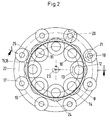
- the device for roll flanging cylindrical body consists essentially of several - here eight - flanging rollers 10, the longitudinal or Rotation axes 11 on a common pitch circle 12 are arranged.
- the flanging rollers 10 each lead a rotational movement (see arrow 13) and roll along the can body 14 or along the emerging flare B.
- the flanging rollers 10 have a lower cylindrical part 15 with a larger one Diameter through whose shoulder or collar 16 the Flare B is formed on the can body 14.
- the Crimping rollers 10 are on the can body facing end conical, with the Part 15 first a steeply conical part 10 'and then connect a flat conical tip 10 ''.
- the Limiting rollers 17 are radially displaceable, what translationally by guide pieces 20 or by a eccentric storage can be done.
- the Boundary rollers 17 are - at least at the time of Contact with the flare B to be produced - see above led them on a respective Bisector between the flanging rollers.
- the flanging rollers 10 and the limiting rollers 17 are stored in a common receptacle 22, which is a centric, coinciding with the can axis Longitudinal axis 23 rotates.
- the result of the flanging process resulting largest diameter can be by the position the limiting rollers 17, namely the determination of the Radius of the pitch circle 19 on which their Axes of rotation 18 are set.
- At predetermined, fixed arrangement of the flanging rollers 10 in the receptacle 22 can by changing the Diameter of the pitch circle 19 the geometric Formation of the flange B, d. H. the flare width to be influenced.
- the limiting rollers 17 are also driven (see arrow 21) so that between the flanging rollers 10 on the one hand and the limiting rollers 17 on the other no relative speed to the can body 14 consists.
- the directions of rotation of the flanging rollers 10 and Limiting rollers 17 are opposite in this case.
- the crimping device To a limited extent also for the crimping device to be able to use other can diameters provided on the flanging rollers 10 in the for Limiting rollers 17 described manner in the sense of Change in the diameter of the pitch circle 12 in the Arrange receptacle 22 displaceable and adjustable.
Landscapes
- Engineering & Computer Science (AREA)
- Mechanical Engineering (AREA)
- Rolls And Other Rotary Bodies (AREA)
- Shaping Metal By Deep-Drawing, Or The Like (AREA)
- Tyre Moulding (AREA)
- Bending Of Plates, Rods, And Pipes (AREA)
Description
- Fig. 1
- eine Bördelvorrichtung für den unteren Rand eines Dosenrumpfes in einem Vertikalschnitt längs der Linie I-I in Fig. 2,
- Fig. 2
- die Bördelvorrichtung in einer teilweise geschnittenen Draufsicht und
- Fig. 3
- eine abgewandelte Ausführungsform der Bördelvorrichtung in einer auszugsweisen Draufsicht.
Claims (13)
- Vorrichtung zum Rollbördeln zumindest im Randbereich zylindrischer Körper (14), mit mehreren Bördelrollen (10) die in einer Aufnahme (22) drehbar gelagert sind und am umzuformenden Zylindermantel des Körpers (14) abwälzen und durch ihre Kontur die Bördelgeometrie formen, und eine den Außendurchmesser des Bördels (B) bestimmende Begrenzungswerkzeuganordnung die - von der Längsachse (23) der Aufnahme (22) gesehen - außerhalb der Bördelrollen (10) angeordnet ist,
dadurch gekennzeichnet,
daß die Begrenzungswerkzeuganordnung einen einstückigen, hülsenförmigen Begrenzungskörper aufweist, der mit Teilen seiner der gemeinsamen Längsachse (23) der Vorrichtung und der zylindrischen Körper (14) zugewandten Innenmantelfläche die zylindrische, durch die die Bördelgeometrie formenden Teile (15) der Bördelrollen (10) gebildete Hüllfläche (25) um die genannte Längsachse (23) zwischen nebeneinanderliegenden Bördelrollen (10) nach innen überragt. - Vorrichtung zum Rollbördeln zumindest im Randbereich zylindrischer Körper (14), mit mehreren Bördelrollen (10), die in einer Aufnahme (22) drehbar gelagert sind und am umzuformenden Zylindermantel des Körpers (14) abwälzen und durch ihre Kontur die Bördelgeometrie formen, und eine den Außendurchmesser des Bördels (B) bestimmende Begrenzungswerkzeuganordnung, die - on der Längsachse (23) der Aufnahme (22) gesehen - außerhalb der Bördelrollen (10) angeordnet ist,
dadurch gekennzeichnet,
daß die Begrenzungswerkzeuganordnung mehrere Begrenzungskörper (17) aufweist, die zumindest bei Erreichen des maximalen Bördeldurchmessers zwischen nebeneinanderliegenden Bördelrollen (10) angeordnet sind und mit ihrer, der gemeinsamen Längsachse (23) der Vorrichtung und der zylindrischen Körper (14) zugewandten Mantelfläche die zylindrische, durch die die Bördelgeometrie formenden Teile (15) der Bördelrollen (10) gebildete Hüllfläche (25) um die genannte Längsachse (23) nach innen überragen. - Vorrichtung nach Anspruch 1 oder 2, dadurch gekennzeichnet, daß die Begrenzungskörper (17) feststehend oder rotationsfähig ausgebildet sind.
- Vorrichtung nach einem der Ansprüche 1 bis 3, dadurch gekennzeichnet, daß die Begrenzungskörper (17) zylinderförmig sind.
- Vorrichtung nach einem der Ansprüche 2 bis 4, dadurch gekennzeichnet, daß zwischen jedem Paar nebeneinanderliegender Bördelrollen (10) mindestens ein Begrenzungskörper (17) vorgesehen ist.
- Vorrichtung nach einem der Ansprüche 2 bis 5, dadurch gekennzeichnet, daß die Begrenzungskörper (17) drehbar gelagerte Rollen sind.
- Vorrichtung nach einem der Ansprüche 2 bis 6, dadurch gekennzeichnet, daß die Längsachsen (18) der Begrenzungsrollen (17) auf einem Kreis (19) liegen.
- Vorrichtung nach einem der Ansprüche 2 bis 7, dadurch gekennzeichnet, daß die Begrenzungsrollen (17) im Sinne einer Veränderung des Abstandes ihrer Längsachsen (18) von der zentralen Längsachse (23) der Vorrichtung verschiebbar angeordnet sind, vorzugsweise in Führungsstücken (20) oder durch eine exzentrische Lagerung.
- Vorrichtung nach einem der Ansprüche 2 bis 8, dadurch gekennzeichnet, daß die Rollen (10, 17) antreibbar sind, vorzugsweise derart, daß die Relativgeschwindigkeit zwischen der Wirkfläche der Begrenzungsrollen (17) und der Kante des Bördels (B) zur Vermeidung von Beschädigungen Null ist.
- Vorrichtung nach einem der Ansprüche 2 bis 9, dadurch gekennzeichnet, daß die Begrenzungskörper` vorzugsweise die Begrenzungsrollen (17) derart angeordnet sind, daß deren Wirkflächen rechtwinklig zur Neigung des Bördels (B) stehen.
- Vorrichtung nach einem der Ansprüche 2 bis 10, dadurch gekennzeichnet, daß die Bördelrollen (10) und die Begrenzungsrollen (17) in einer gemeinsamen Aufnahme (22) gelagert sind, die um eine mit der Achse des zylindrischen Körpers (14) zusammenfallende zentrale Achse (23) rotierbar ausgebildet ist.
- Vorrichtung nach einem der Ansprüche 2 bis 11, dadurch gekennzeichnet, daß die Bördelrollen (10) im Sinne einer Veränderung des Abstandes ihrer Drehachsen (11) von der zentralen Längsachse (23) verschiebbar angeordnet sind, vorzugsweise in Führungsstücken (20) oder durch eine exzentrische Lagerung.
- Vorrichtung nach einem der Ansprüche 2 bis 12, dadurch gekennzeichnet, daß die Begrenzungskörper (17) so ausgeformt sind, daß durch sie eine zusätzliche Bördelumformung bewirkbar ist.
Applications Claiming Priority (2)
| Application Number | Priority Date | Filing Date | Title |
|---|---|---|---|
| DE4315214A DE4315214A1 (de) | 1993-05-07 | 1993-05-07 | Vorrichtung zum Rollbördeln zylindrischer Körper |
| DE4315214 | 1993-05-07 |
Publications (2)
| Publication Number | Publication Date |
|---|---|
| EP0623405A1 EP0623405A1 (de) | 1994-11-09 |
| EP0623405B1 true EP0623405B1 (de) | 1998-12-23 |
Family
ID=6487476
Family Applications (1)
| Application Number | Title | Priority Date | Filing Date |
|---|---|---|---|
| EP94106168A Expired - Lifetime EP0623405B1 (de) | 1993-05-07 | 1994-04-21 | Vorrichtung zum Rollbördeln zylindrischer Körper |
Country Status (6)
| Country | Link |
|---|---|
| US (1) | US5477720A (de) |
| EP (1) | EP0623405B1 (de) |
| CN (1) | CN1056105C (de) |
| DE (2) | DE4315214A1 (de) |
| ES (1) | ES2125366T3 (de) |
| TW (1) | TW276198B (de) |
Families Citing this family (33)
| Publication number | Priority date | Publication date | Assignee | Title |
|---|---|---|---|---|
| FR2736584B1 (fr) * | 1995-07-12 | 1997-09-26 | Petit Georges Ets Sa | Procede de fabrication d'un fut en carton kraft |
| DE19528728C2 (de) * | 1995-08-04 | 1997-12-18 | Klaus Hennek | Vorrichtung zum Bombieren von Falzdachelementen |
| DE19536053C2 (de) * | 1995-09-28 | 2001-05-31 | Schaeffler Waelzlager Ohg | Unter Anwendung eines Spanlosverfahrens hergestellter Endanschlag an einer Schaltarretierung |
| US5813267A (en) * | 1996-02-28 | 1998-09-29 | Crown Cork & Seal Company, Inc. | Methods and apparatus for reducing flange width variations in die necked container bodies |
| DE19628995A1 (de) * | 1996-07-18 | 1998-01-22 | Krupp Kunststofftechnik Gmbh | Vorrichtung zum Bördeln von Dosenkörpern |
| US6032502A (en) * | 1998-08-31 | 2000-03-07 | American National Can Co. | Apparatus and method for necking containers |
| US6163951A (en) * | 1999-03-31 | 2000-12-26 | Sealright Co., Inc. | Method and apparatus for lifting tabs of a laminate from a substrate |
| DE10061087A1 (de) * | 2000-12-08 | 2002-06-13 | Trw Automotive Safety Sys Gmbh | Verfahren zum Herstellen eines Lenkradskeletts und Fahrzeuglenkrad |
| US6935152B2 (en) | 2002-04-16 | 2005-08-30 | Victaulic Company Of America | Orbiting roller groover for pipe |
| US6993949B2 (en) * | 2004-02-12 | 2006-02-07 | Victaulic Company | Power or manually operated pipe grooving tool |
| US7353579B2 (en) * | 2005-01-28 | 2008-04-08 | Pratt & Whitney Canada Corp. | Flange restoring device and method |
| CN100349665C (zh) * | 2005-12-02 | 2007-11-21 | 姚中沃 | 圆型器皿的加框机 |
| CN100349666C (zh) * | 2005-12-02 | 2007-11-21 | 姚中沃 | 一种圆型器皿的加框机的转盘组件 |
| CN101396705B (zh) * | 2007-09-27 | 2011-03-16 | 董明祥 | 一种金属筒体翻边设备 |
| DE102010025554B4 (de) | 2010-06-29 | 2020-08-13 | Dbw Advanced Fiber Technologies Gmbh | Formteil zur thermischen, akustischen und mechanischen Abschirmung eines Bauteils |
| US20120137746A1 (en) * | 2010-12-07 | 2012-06-07 | Lennox Hearth Products LLC | Swaging machine |
| EP2524741B1 (de) | 2011-05-16 | 2014-12-24 | Alcatel Lucent | Vorrichtung zum Flanschen des Endes eines Metallrohres |
| CN103212656B (zh) * | 2012-01-18 | 2014-11-26 | 番禺珠江钢管有限公司 | 管端保护器轧机 |
| CN102632122B (zh) * | 2012-04-20 | 2013-12-18 | 山东开泰抛丸机械有限公司 | 圆管端面咬口机 |
| CN102773321A (zh) * | 2012-08-20 | 2012-11-14 | 昆山捷兴翡国际贸易有限公司 | 一种薄壁管双翻法兰成型设备 |
| CN104433773A (zh) * | 2014-02-25 | 2015-03-25 | 李和竹 | 一种蒸笼成型机 |
| CN104117561B (zh) * | 2014-07-17 | 2016-03-23 | 苏州华源包装股份有限公司 | 一种卷边机构 |
| CN104300450A (zh) * | 2014-11-12 | 2015-01-21 | 国家电网公司 | 一种手动旋压金属护套成型器 |
| US10144048B2 (en) * | 2014-11-19 | 2018-12-04 | Ford Global Technologies, Llc | High stiffness and high access forming tool for incremental sheet forming |
| CN104438526B (zh) * | 2014-11-28 | 2017-01-11 | 芜湖贝斯特新能源开发有限公司 | 金属筒翻边机 |
| CN105834267B (zh) * | 2015-02-02 | 2019-12-06 | 斯科特科技有限公司 | 轧制成形设备和轧制成形方法 |
| CN104959433B (zh) * | 2015-05-22 | 2017-01-25 | 黄伟 | 管接件成型滚压设备及其使用方法 |
| CN104985041B (zh) * | 2015-06-15 | 2017-02-01 | 浙江上风高科专风实业有限公司 | 一种风筒翻边机及其使用方法 |
| CN106111767B (zh) * | 2016-08-22 | 2018-12-21 | 佛山市南海九洲普惠风机有限公司 | 一种法兰盘自动翻边机 |
| CN113477767B (zh) * | 2021-05-26 | 2023-06-30 | 湖南振辉管业有限公司 | 一种用于金属塑料复合管的压边装置 |
| CN113714363B (zh) * | 2021-09-06 | 2023-10-20 | 镇海石化建安工程股份有限公司 | 一种用于螺旋板换热器芯体的翻边设备 |
| CN114309198B (zh) * | 2022-03-16 | 2022-06-03 | 徐州华恒机器人系统有限公司 | 一种大直径变截面筒体翻边机 |
| CN115488249B (zh) * | 2022-11-16 | 2023-03-24 | 卫辉市卫新机械有限公司 | 一种具有拼装料筒结构立式饲料混合机的料筒成型装置 |
Family Cites Families (11)
| Publication number | Priority date | Publication date | Assignee | Title |
|---|---|---|---|---|
| DE416539C (de) * | 1924-09-09 | 1925-07-17 | Zimmermann Fa G | Verfahren und Vorrichtung zur Herstellung von Metallrahmen |
| FR748912A (fr) * | 1932-04-07 | 1933-07-13 | Dispositif pour le sertissage et le roulage simultanés de boîtes en fer blanc et autres | |
| US2250799A (en) * | 1939-03-22 | 1941-07-29 | John K M Harrison | Container bottom and top spinning head |
| US3633469A (en) * | 1970-06-11 | 1972-01-11 | Phillips Petroleum Co | Rim curling apparatus and method |
| DE2257210A1 (de) * | 1972-11-22 | 1974-05-30 | Metal Box Co Ltd | Verfahren und vorrichtung zur herstellung eines metallenen dosenkoerpers |
| DE7621025U1 (de) * | 1976-07-02 | 1976-11-25 | Alcan Aluminiumwerke Gmbh, 3400 Goettingen | Werkzeug zum boerdeln des randes zylindrischer hohler werkstuecke, insbesondere von dosenrohlingen |
| US4747287A (en) * | 1981-02-05 | 1988-05-31 | American National Can Company | Inclined axes spin flanging head and method for using same |
| JPH07100204B2 (ja) * | 1987-10-08 | 1995-11-01 | 三菱重工業株式会社 | 缶詰缶の巻締方法 |
| US5121621A (en) * | 1991-02-20 | 1992-06-16 | Ihly Industries, Inc. | Preformed flange reforming process and apparatus |
| US5150595A (en) * | 1991-05-09 | 1992-09-29 | Ihly Industries, Inc. | Process and apparatus for working an edge portion of a container flange |
| US5235839A (en) * | 1992-07-29 | 1993-08-17 | Reynolds Metals Company | Apparatus for flanging containers |
-
1993
- 1993-05-07 DE DE4315214A patent/DE4315214A1/de not_active Withdrawn
-
1994
- 1994-04-21 EP EP94106168A patent/EP0623405B1/de not_active Expired - Lifetime
- 1994-04-21 ES ES94106168T patent/ES2125366T3/es not_active Expired - Lifetime
- 1994-04-21 DE DE59407511T patent/DE59407511D1/de not_active Expired - Fee Related
- 1994-05-05 US US08/238,323 patent/US5477720A/en not_active Expired - Fee Related
- 1994-05-05 CN CN94104889A patent/CN1056105C/zh not_active Expired - Fee Related
- 1994-06-16 TW TW083105468A patent/TW276198B/zh active
Also Published As
| Publication number | Publication date |
|---|---|
| CN1100012A (zh) | 1995-03-15 |
| US5477720A (en) | 1995-12-26 |
| DE4315214A1 (de) | 1994-11-10 |
| DE59407511D1 (de) | 1999-02-04 |
| ES2125366T3 (es) | 1999-03-01 |
| EP0623405A1 (de) | 1994-11-09 |
| TW276198B (de) | 1996-05-21 |
| CN1056105C (zh) | 2000-09-06 |
Similar Documents
| Publication | Publication Date | Title |
|---|---|---|
| EP0623405B1 (de) | Vorrichtung zum Rollbördeln zylindrischer Körper | |
| DE3118783A1 (de) | Verfahren und vorrichtung zum verformen der ruempfe von blechdosen und vorrichtung zur ausfuehrung dieses verfahrens | |
| DE2624854C3 (de) | Rollendrückvorrichtung zum Herstellen eines becherförmigen Riemenscheiben-Rohteils | |
| DE3725186C2 (de) | ||
| DE60027889T2 (de) | Verfahren und Biegevorrichtung zum Biegen eines gebogenen Werkstückes | |
| DE2144863C3 (de) | Vorrichtung zum Schließen des Endes eines rohrförmigen Metallwerkstückes | |
| EP0394531B1 (de) | Falzmaschine | |
| EP0254134B1 (de) | Maschine zum beiderseitigen Bördeln und Einziehen zylindrischer Dosenrümpfe | |
| EP0772501B1 (de) | Verfahren zur bildung eines geneckten und gebördelten abschnitts an einem zylindrischen hohlkörper und vorrichtung zum durchführen des verfahrens | |
| DE3617139C2 (de) | ||
| DE19628995A1 (de) | Vorrichtung zum Bördeln von Dosenkörpern | |
| DE2834149C2 (de) | Abrichtvorrichtung für eine mit einer Topfschleifscheibe arbeitende Vorrichtung zum Schleifen bogenverzahnter Kegelräder | |
| EP0379977A1 (de) | Trommel für die Aufnahme eines Seiles | |
| DE19511963C2 (de) | Verfahren zur Herstellung von rotationssymmetrischen metallischen Werkstücken | |
| DE2415805A1 (de) | Vorrichtung zur umformung von rotationsgegenstaenden durch keilquerwalzen mit drei walzen | |
| DE2257210A1 (de) | Verfahren und vorrichtung zur herstellung eines metallenen dosenkoerpers | |
| DE2502306A1 (de) | Verfahren und vorrichtung zum formen der aussenflaeche von gegenstaenden aus verformbarem material | |
| EP0674563B1 (de) | Vorrichtung zum trennen einer mehrfach hohen dosenzarge | |
| EP0918582B1 (de) | Bördelvorrichtung | |
| DE3632436C2 (de) | Radial-Axial-Ringwalzmaschine | |
| DE2825234C2 (de) | Vorrichtung zum Herstellen gewölbter Abschlußwände | |
| DE2922433C2 (de) | Vorrichtung zum kontinuierlichen Strangpressen von Draht, Stangen oder dergleichen | |
| DE19623866C2 (de) | Verfahren und Vorrichtung zum Herstellen von rotationssymmetrischen Werkstücken, insbesondere Fahrzeugrädern | |
| DE19625231A1 (de) | Vorrichtung zum Herstellen von rundkonischen Rohren | |
| DE3522253C2 (de) |
Legal Events
| Date | Code | Title | Description |
|---|---|---|---|
| PUAI | Public reference made under article 153(3) epc to a published international application that has entered the european phase |
Free format text: ORIGINAL CODE: 0009012 |
|
| AK | Designated contracting states |
Kind code of ref document: A1 Designated state(s): CH DE ES FR GB IT LI NL |
|
| 17P | Request for examination filed |
Effective date: 19950420 |
|
| 17Q | First examination report despatched |
Effective date: 19970425 |
|
| RAP1 | Party data changed (applicant data changed or rights of an application transferred) |
Owner name: KRUPP KUNSTSTOFFTECHNIK GMBH |
|
| GRAG | Despatch of communication of intention to grant |
Free format text: ORIGINAL CODE: EPIDOS AGRA |
|
| GRAG | Despatch of communication of intention to grant |
Free format text: ORIGINAL CODE: EPIDOS AGRA |
|
| GRAH | Despatch of communication of intention to grant a patent |
Free format text: ORIGINAL CODE: EPIDOS IGRA |
|
| GRAH | Despatch of communication of intention to grant a patent |
Free format text: ORIGINAL CODE: EPIDOS IGRA |
|
| GRAA | (expected) grant |
Free format text: ORIGINAL CODE: 0009210 |
|
| AK | Designated contracting states |
Kind code of ref document: B1 Designated state(s): CH DE ES FR GB IT LI NL |
|
| REG | Reference to a national code |
Ref country code: CH Ref legal event code: NV Representative=s name: PATENTANWALTSBUERO EDER AG Ref country code: CH Ref legal event code: EP |
|
| GBT | Gb: translation of ep patent filed (gb section 77(6)(a)/1977) |
Effective date: 19981223 |
|
| REF | Corresponds to: |
Ref document number: 59407511 Country of ref document: DE Date of ref document: 19990204 |
|
| ET | Fr: translation filed | ||
| REG | Reference to a national code |
Ref country code: ES Ref legal event code: FG2A Ref document number: 2125366 Country of ref document: ES Kind code of ref document: T3 |
|
| ITF | It: translation for a ep patent filed |
Owner name: STUDIO JAUMANN P. & C. S.N.C. |
|
| PLBQ | Unpublished change to opponent data |
Free format text: ORIGINAL CODE: EPIDOS OPPO |
|
| PLBI | Opposition filed |
Free format text: ORIGINAL CODE: 0009260 |
|
| PLBF | Reply of patent proprietor to notice(s) of opposition |
Free format text: ORIGINAL CODE: EPIDOS OBSO |
|
| 26 | Opposition filed |
Opponent name: LANICO-MASCHINENBAU OTTO NIEMSCH GMBH Effective date: 19990923 |
|
| NLR1 | Nl: opposition has been filed with the epo |
Opponent name: LANICO-MASCHINENBAU |
|
| PLBF | Reply of patent proprietor to notice(s) of opposition |
Free format text: ORIGINAL CODE: EPIDOS OBSO |
|
| PGFP | Annual fee paid to national office [announced via postgrant information from national office to epo] |
Ref country code: NL Payment date: 20000320 Year of fee payment: 7 |
|
| PLBF | Reply of patent proprietor to notice(s) of opposition |
Free format text: ORIGINAL CODE: EPIDOS OBSO |
|
| PLBL | Opposition procedure terminated |
Free format text: ORIGINAL CODE: EPIDOS OPPC |
|
| PGFP | Annual fee paid to national office [announced via postgrant information from national office to epo] |
Ref country code: GB Payment date: 20010316 Year of fee payment: 8 |
|
| PGFP | Annual fee paid to national office [announced via postgrant information from national office to epo] |
Ref country code: CH Payment date: 20010319 Year of fee payment: 8 |
|
| PLBM | Termination of opposition procedure: date of legal effect published |
Free format text: ORIGINAL CODE: 0009276 |
|
| STAA | Information on the status of an ep patent application or granted ep patent |
Free format text: STATUS: OPPOSITION PROCEDURE CLOSED |
|
| PGFP | Annual fee paid to national office [announced via postgrant information from national office to epo] |
Ref country code: FR Payment date: 20010410 Year of fee payment: 8 |
|
| PGFP | Annual fee paid to national office [announced via postgrant information from national office to epo] |
Ref country code: ES Payment date: 20010417 Year of fee payment: 8 |
|
| PGFP | Annual fee paid to national office [announced via postgrant information from national office to epo] |
Ref country code: DE Payment date: 20010421 Year of fee payment: 8 |
|
| 27C | Opposition proceedings terminated |
Effective date: 20001218 |
|
| REG | Reference to a national code |
Ref country code: FR Ref legal event code: TP Ref country code: FR Ref legal event code: CD |
|
| NLR2 | Nl: decision of opposition | ||
| PG25 | Lapsed in a contracting state [announced via postgrant information from national office to epo] |
Ref country code: NL Free format text: LAPSE BECAUSE OF NON-PAYMENT OF DUE FEES Effective date: 20011101 |
|
| REG | Reference to a national code |
Ref country code: GB Ref legal event code: IF02 |
|
| NLV4 | Nl: lapsed or anulled due to non-payment of the annual fee |
Effective date: 20011101 |
|
| PG25 | Lapsed in a contracting state [announced via postgrant information from national office to epo] |
Ref country code: GB Free format text: LAPSE BECAUSE OF NON-PAYMENT OF DUE FEES Effective date: 20020421 |
|
| PG25 | Lapsed in a contracting state [announced via postgrant information from national office to epo] |
Ref country code: ES Free format text: LAPSE BECAUSE OF NON-PAYMENT OF DUE FEES Effective date: 20020422 |
|
| PG25 | Lapsed in a contracting state [announced via postgrant information from national office to epo] |
Ref country code: LI Free format text: LAPSE BECAUSE OF NON-PAYMENT OF DUE FEES Effective date: 20020430 Ref country code: CH Free format text: LAPSE BECAUSE OF NON-PAYMENT OF DUE FEES Effective date: 20020430 |
|
| PG25 | Lapsed in a contracting state [announced via postgrant information from national office to epo] |
Ref country code: DE Free format text: LAPSE BECAUSE OF NON-PAYMENT OF DUE FEES Effective date: 20021101 |
|
| GBPC | Gb: european patent ceased through non-payment of renewal fee |
Effective date: 20020421 |
|
| REG | Reference to a national code |
Ref country code: CH Ref legal event code: PL |
|
| PG25 | Lapsed in a contracting state [announced via postgrant information from national office to epo] |
Ref country code: FR Free format text: LAPSE BECAUSE OF NON-PAYMENT OF DUE FEES Effective date: 20021231 |
|
| REG | Reference to a national code |
Ref country code: FR Ref legal event code: ST |
|
| REG | Reference to a national code |
Ref country code: ES Ref legal event code: FD2A Effective date: 20030514 |
|
| PG25 | Lapsed in a contracting state [announced via postgrant information from national office to epo] |
Ref country code: IT Free format text: LAPSE BECAUSE OF NON-PAYMENT OF DUE FEES Effective date: 20050421 |
|
| PLAB | Opposition data, opponent's data or that of the opponent's representative modified |
Free format text: ORIGINAL CODE: 0009299OPPO |