EP0619405A1 - System for protection and reinforcement of the bases of partition walls in industial buidings - Google Patents
System for protection and reinforcement of the bases of partition walls in industial buidings Download PDFInfo
- Publication number
- EP0619405A1 EP0619405A1 EP94460009A EP94460009A EP0619405A1 EP 0619405 A1 EP0619405 A1 EP 0619405A1 EP 94460009 A EP94460009 A EP 94460009A EP 94460009 A EP94460009 A EP 94460009A EP 0619405 A1 EP0619405 A1 EP 0619405A1
- Authority
- EP
- European Patent Office
- Prior art keywords
- modules
- groove
- ground
- envelope
- base
- Prior art date
- Legal status (The legal status is an assumption and is not a legal conclusion. Google has not performed a legal analysis and makes no representation as to the accuracy of the status listed.)
- Ceased
Links
Images


Classifications
-
- E—FIXED CONSTRUCTIONS
- E04—BUILDING
- E04H—BUILDINGS OR LIKE STRUCTURES FOR PARTICULAR PURPOSES; SWIMMING OR SPLASH BATHS OR POOLS; MASTS; FENCING; TENTS OR CANOPIES, IN GENERAL
- E04H5/00—Buildings or groups of buildings for industrial or agricultural purposes
- E04H5/10—Buildings forming part of cooling plants
-
- E—FIXED CONSTRUCTIONS
- E04—BUILDING
- E04F—FINISHING WORK ON BUILDINGS, e.g. STAIRS, FLOORS
- E04F19/00—Other details of constructional parts for finishing work on buildings
- E04F19/02—Borders; Finishing strips, e.g. beadings; Light coves
- E04F19/04—Borders; Finishing strips, e.g. beadings; Light coves for use between floor or ceiling and wall, e.g. skirtings
-
- E—FIXED CONSTRUCTIONS
- E04—BUILDING
- E04F—FINISHING WORK ON BUILDINGS, e.g. STAIRS, FLOORS
- E04F19/00—Other details of constructional parts for finishing work on buildings
- E04F19/02—Borders; Finishing strips, e.g. beadings; Light coves
- E04F19/026—Borders; Finishing strips, e.g. beadings; Light coves specially adapted for cushioning impacts
-
- E—FIXED CONSTRUCTIONS
- E04—BUILDING
- E04F—FINISHING WORK ON BUILDINGS, e.g. STAIRS, FLOORS
- E04F19/00—Other details of constructional parts for finishing work on buildings
- E04F19/02—Borders; Finishing strips, e.g. beadings; Light coves
- E04F19/04—Borders; Finishing strips, e.g. beadings; Light coves for use between floor or ceiling and wall, e.g. skirtings
- E04F19/045—Hygienic or watertight plinths
-
- E—FIXED CONSTRUCTIONS
- E04—BUILDING
- E04F—FINISHING WORK ON BUILDINGS, e.g. STAIRS, FLOORS
- E04F19/00—Other details of constructional parts for finishing work on buildings
- E04F19/02—Borders; Finishing strips, e.g. beadings; Light coves
- E04F19/04—Borders; Finishing strips, e.g. beadings; Light coves for use between floor or ceiling and wall, e.g. skirtings
- E04F2019/0404—Borders; Finishing strips, e.g. beadings; Light coves for use between floor or ceiling and wall, e.g. skirtings characterised by the material
- E04F2019/0422—Borders; Finishing strips, e.g. beadings; Light coves for use between floor or ceiling and wall, e.g. skirtings characterised by the material of organic plastics with or without reinforcements or filling materials
-
- E—FIXED CONSTRUCTIONS
- E04—BUILDING
- E04F—FINISHING WORK ON BUILDINGS, e.g. STAIRS, FLOORS
- E04F19/00—Other details of constructional parts for finishing work on buildings
- E04F19/02—Borders; Finishing strips, e.g. beadings; Light coves
- E04F19/04—Borders; Finishing strips, e.g. beadings; Light coves for use between floor or ceiling and wall, e.g. skirtings
- E04F2019/0404—Borders; Finishing strips, e.g. beadings; Light coves for use between floor or ceiling and wall, e.g. skirtings characterised by the material
- E04F2019/0431—Borders; Finishing strips, e.g. beadings; Light coves for use between floor or ceiling and wall, e.g. skirtings characterised by the material of two or more materials
Definitions
- the present invention relates to the field of construction of industrial buildings, and more particularly to the fitting out of interior partitions.
- the current technique consists in bringing back to the base of the partitions, a concrete sidewall called a bench seat: more precisely, the partition panels are placed in a rail anchored to the ground, then the concrete bench seat is poured along the panels.
- the bench may be covered with an envelope, usually made of stainless steel.
- the invention was carried out with the aim of overcoming these various drawbacks.
- a protection and reinforcement system for the lower part of partitions characterized in that it comprises a sole of a certain height, the top of which comprises a groove for receiving the base of partition panels, which sole is formed from prefabricated modules arranged end to end, each comprising means for being fixed to the ground and to the modules neighbors, and consisting of an open envelope at its base and at its ends, into which a block of material such as light concrete or synthetic foam has been poured before installation.
- Said sole defines a sidewall at the base of the partition to be protected. If the partition must be protected on both sides as in most cases, the sole is double, that is to say that it defines a sidewall on each side.
- said envelope is made of stainless steel, and it is loaded with a light and insulating concrete, based on polystyrene for example.
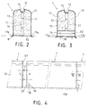
- Fig. 1 therefore illustrates the invention, implemented to provide protection and reinforcement in the lower part on both sides of a partition C. Conventionally, this consists of prefabricated panels juxtaposed 2.
- a continuous sole S prior to the installation of the panels, is provided over the entire length of the partition C, a continuous sole S, fixed firmly to the ground.
- the sole S has a substantial width relative to the thickness of the panels 2, and a height which, generally, is between 20 and 50 cm.
- the sole S consists of a series of identical modules 1 placed end to end, which essentially comprise a casing 10 open at its base and at its ends, advantageously made of stainless steel, and filled with a filler material forming a block 11, good thermal insulator and having appropriate mechanical properties. It can be a synthetic foam or a light concrete, based on polystyrene beads for example. Each module is fixed to the ground and to the module previously installed.
- the casing 10 defines at the top of the module 1 a longitudinal groove 12 intended to receive the base of the partition panels 2.
- the sole S therefore forms two sides on each side of the base, brought to be in different rooms where the temperature conditions can be very different. It is therefore necessary to eliminate as much as possible the thermal bridges between the two parts of the envelope 10 on each side of the groove 12.
- the envelope 10 is subdivided symmetrically into two pieces of sheet metal 13, each folded so as to present a vertical panel, an upper panel with double inclination, and an upper rim forming a part of the groove 12.
- the two sheet metal parts 13 are joined at the bottom of the groove 12 only by a few transverse isthmus 14 regularly spaced. Similarly, at their base, they are only joined at the ends of the module.
- the bottom connection of the parts 13 is provided by a flat transverse cross member 15.
- a median upright 16 connects the latter to the bottom of the groove 12, which upright carries two centering pins 17 arranged one above the other.
- a flat cross member 18 connects the two parts 13 similarly to the cross member 15.
- the cross member 18 is surmounted by an angle iron 19 which defines with it a space 20 open towards the outside.
- a median upright 21 connects the top of the angle 19 and the bottom of the groove 12, which has holes 22 for receiving the centering pins 17.
- the crosspiece 18 has two or more spaced holes, provided for receiving fixing screws to the ground.
- the concrete or foam block 11 comes flush with the outer face of the uprights 16 and 21, the outer edge of the cross member 15 and that of the angle iron 19. It completely fills the envelope 10 and constitutes the ground support of the module.
- the modules 1 must be fixed securely, as in many applications, in particular in the field of the food industry, and for hygienic reasons, a correct seal is necessary between the lower edges of the envelope 10 and the ground.
- the lower edges 13a, 13b of the casing 10, FIGS. 2, 3, protrude downward relative to the underside of the block 11.
- junction can be achieved by means of a seal, for example made of rubber, having two opposite grooves for receiving said edges.
- a seal for example made of rubber, having two opposite grooves for receiving said edges.
- the junction is produced by interlocking, a strip 23 forming the male part being welded to the internal face of the casing 10, projecting from its edge at one end, while at the other end, the female part or groove results from the superimposition by welding on the same internal face of the envelope of a first strip 24 set back from the edge, and of a second strip 25.
- a first module 1 is put in place. It is anchored in the ground at the level of the cross-member 18, the space 20 being provided to allow screwing. The module is therefore held by this end, and over its entire length by the lower edges of the envelope engaged in the ground.
- a second module 1 is placed after the first. It is connected to it by the centering pins 17, and by interlocking the adjacent edges of their envelopes, as illustrated in FIGS. 4 and 6. As can be seen in this last figure, the blocks 11 of filler material are then applied one against the other, of so there is no break in insulation.
- the second module is anchored to the ground at its free end, by screwing the crosspiece 18. This is done over the entire length of the partition to be built, after which the panels 2 are placed in the grooves 12. If water, electricity, compressed air, etc. are installed along the partition, cleaning passages for the pipes or sheaths in the block 11 and the casing 10 of the corresponding module before its installation.
- a passage is shown in FIG. 12, consisting of a horizontal tube 26 embedded in the block 11 and opening at the end. The tube 26 can pass right through the module, or stop at the point of a tap in the casing 10.
- Fig. 14 schematically shows such a tap 27 in the upper panel of the wall 13 of a module, tap made with an external collar, at the end of a vertical hole in the block 11, for the passage of a conduit outlet 28.
- the collar is welded to the duct 28, which is connected below a sink or hand basin 29 fixed above the module, against the partition panel 2.
- modules can be provided, in the form of T, L and X. It is also possible to provide a range of modules shorter than modules 1, to directly make S soles whatever their length.
- the module 1 'shown in FIG. 7 is used to make a single sole, that is to say a sole forming reinforcement only on one side.
- This module is in all respects similar to the module 1 described above, comprising a block 11 of insulating filler material, an envelope 10 ′ in two parts 13, 13 ′ joined by points, with the same end means: low crosspieces, angle iron, uprights, centering pins.
- the part 13 ′ of the envelope is not shouldered, so that the groove 12, instead of being central, is offset on the outside of the module, its outer edge being perpendicular to the vertical wall of the envelope part 13 '.
- a single lower edge 13a of the casing 10 ′ is extended beyond the base of the block 11 which constitutes the bearing surface of the module, hence the need for a single groove in the floor for laying.
- the lower edge of the part 13 ′ can also be extended, if the sealing on the outside needs to be carried out with as much care as on the inside.
- Modules 3 and 3 'of Figs. 8 to 10 differ very little from modules 1 and 1 'in their structure. Like them, they comprise an envelope 10 or 10 ′ enclosing a block of insulating material 11 and defining an upper groove 12 for receiving partition elements 2.
- the block 11 does not completely fill the volume delimited by the envelope 10 or 10 ', but rather, there is reserved a free space 30 intended to receive a sealing concrete, which can be flowed through channels 31 passing through the block 11 from the bottom of the groove 12.
- a cross 18 with an angle 19 to define a space 20 are reproduced at the two ends of the modules 3 and 3 '.
- jacks 32 are mounted in place of screws for fixing to the ground, which is carried out by means of rods 34 engaged from the groove 12 in calibrated channels 33 passing through the block 11, and in holes in the ground aligned with the channels 33.
- the angle 19, and therefore the space 20 above the crosspiece 18 are eliminated, the screw of the jacks 32 being covered above the cross member 18, by means of a closed tube portion, for example.
- the modules 3 or 3 ' are first arranged on a first slab 35, the lower edge of the casings 10 or 10' being slightly raised. They are connected end to end by the adjacent end edges of their casings 10 or 10 ', the jacks 32 allowing adjustment. Then, drilling means are engaged in the channels 33 to provide in the slab for receiving the rods 34 which are then put in place. Note that an advantage of this method of fixing lies in the possibility of fixing the last module arriving against a pre-existing wall or partition.
- the sealing concrete is poured through the channels 31, which comes slightly beyond laterally under the lower edges of the modules. Finally, a finishing slab drowns these lower edges, symbolized by the thin line 36.
- the waterproofing concrete is poured at the desired height just before the installation of the modules 3 and 3 ', the channels 31 then serving as an overflow for the excess concrete.
- the modules can be placed on the slab carrying the floor covering, after a strip of it has been cut and removed.
- a connecting and sealing tape 37 is used, for example of the same material as the casing 10, which is housed by its two sides in two grooves formed in the end edges of the casings 10, by welding by strip points 24 and 25 as previously described.
- the T-module of FIG. 12, bearing the mark 4 is used for the T-junction of two partitions. As shown, its two branches 4b and 4c are single sole elements, and its foot 4a is a double sole element.
- the sheet metal parts 13 of its casing 10 have only one inclined section instead of two above the vertical section. Its slope is preferably at least greater than 30 ° relative to the horizontal, to ensure good flow of the washing water.
- the walls 13 and 13 ' have, at some distance above their lower edge, a small longitudinal recess 40.
- a set of wires is added by welding crossed 42, which is used for attaching a cement or finishing resin, with which one comes to form for example a rounding as shown schematically by the broken line in FIG. 13.
- the recess 41 can be provided to admit tiling.
- the sheet is normal to the vertical plane of the wall 13; and on the surface of the hollow 41, it is advantageously perforated to ensure better attachment of the fixing adhesive to the tiling.
- lateral tabs 43 added by welding to the bottom of its walls 13 and 13 ′ may be provided, which will be screwed or pointed, before being covered with cement or finishing resin, or by the tiling.
- the element 4b of the module 4 is shown incomplete, without its filling concrete 11, to reveal its internal structure.
- the filling concrete 11 is visible in the element 4a and in FIG. 13: it is stopped very close to the lower edge of the walls 13, the free space 30 reserved for the admission of sealing concrete having a very reduced uniform height, of the order of 1 to 2 cm.
- the realization of the waterproofing concrete according to the technique of pouring it at the desired height before the installation of the module is facilitated.
- variant modules according to the invention can combine the characteristics of two modules 1, 3 and 4, or 1 'and 3'.
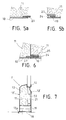
- Fig. 15 shows a module 5 designed to make the end of a sole S adjacent to a door, of which the frame conventionally comprises uprights with a U-shaped section 50 to engage on the edge of the partition panels 2.
- the side wall 13 of the envelope of the module 5 is extended by a wall 51 which completely covers the end.
- the wall 50 forms an obtuse angle with it, advantageously of the order of 135 °, to allow correct release of the door leaves during opening.
- a section of U-shaped section 52 is placed vertically on the end, welded by the end of its wings to the wall 50.
- Said section 52 has a width equal to the thickness of the partition panels 2.
- the system of the invention is much simpler and faster to use than the other known systems.
- the disassembly of a sole poses no problem and, of course, the modules which constituted it are perfectly reusable.
- the system of the invention induces a significant cost reduction at the level of the panels 2, the surface of which is reduced by the height of the sole S.
Abstract
Description
La présente invention concerne le domaine de la construction de bâtiments industriels, et plus particulièrement l'aménagement de cloisons intérieures.The present invention relates to the field of construction of industrial buildings, and more particularly to the fitting out of interior partitions.
Ces cloisons, généralement constituées de panneaux légers préfabriqués se doivent d'être protégées et renforcées en partie basse, vu les chocs importants auxquelles elles sont exposées en permanence, notamment de la part des différents engins de manutention.These partitions, generally made up of light prefabricated panels must be protected and reinforced in the lower part, given the significant shocks to which they are permanently exposed, in particular on the part of the various handling machines.
La technique actuelle consiste à rapporter à la base des cloisons, un flanc en béton appelé banquette : plus précisément, les panneaux de cloison sont posés dans un rail ancré au sol, puis la banquette de béton est coulée le long des panneaux. La banquette est éventuellement habillée d'une enveloppe, habituellement en acier inoxydable.The current technique consists in bringing back to the base of the partitions, a concrete sidewall called a bench seat: more precisely, the partition panels are placed in a rail anchored to the ground, then the concrete bench seat is poured along the panels. The bench may be covered with an envelope, usually made of stainless steel.
Cette technique souffre de plusieurs inconvénients parmi lesquels le temps d'installation dû à l'importance du coffrage à réaliser, et l'aspect définitif de l'implantation des cloisons. Concernant le coffrage, on peut adopter un processus simplifié si la banquette doit être recouverte d'acier inoxydable : l'enveloppe métallique est d'abord mise en place, puis le béton y est coulé par des ouvertures prévues à cet effet dans la paroi supérieure. Toutefois, cette mise en oeuvre reste lourde et ne résout en rien le problème de l'inamovibilité ci-dessus invoqué.This technique suffers from several drawbacks, including the installation time due to the size of the formwork to be produced, and the final aspect of the installation of the partitions. Regarding the formwork, we can adopt a simplified process if the bench must be covered with stainless steel: the metal casing is first put in place, then the concrete is poured into it through openings provided for this purpose in the upper wall . However, this implementation remains cumbersome and does not in any way solve the problem of irremovability mentioned above.
L'invention a été réalisée dans le but de pallier ces divers inconvénients.The invention was carried out with the aim of overcoming these various drawbacks.
Elle consiste en un système de protection et de renfort de la partie basse de cloisons, caractérisé en ce qu'il comprend une semelle d'une certaine hauteur dont le sommet comporte une gorge de réception de la base de panneaux de cloison, laquelle semelle est formée à partir de modules préfabriqués disposés bout à bout, chacun comportant des moyens pour être fixé au sol et aux modules voisins, et étant constitué d'une enveloppe ouverte à sa base et à ses extrémités, dans laquelle a été coulé avant la pose un bloc de matériau tel que béton léger ou mousse synthétique.It consists of a protection and reinforcement system for the lower part of partitions, characterized in that it comprises a sole of a certain height, the top of which comprises a groove for receiving the base of partition panels, which sole is formed from prefabricated modules arranged end to end, each comprising means for being fixed to the ground and to the modules neighbors, and consisting of an open envelope at its base and at its ends, into which a block of material such as light concrete or synthetic foam has been poured before installation.
Ladite semelle définit un flanc à la base de la cloison à protéger. Si la cloison doit être protégée des deux côtés comme dans la majorité des cas, la semelle est double, à savoir qu'elle définit un flanc de chaque côté.Said sole defines a sidewall at the base of the partition to be protected. If the partition must be protected on both sides as in most cases, the sole is double, that is to say that it defines a sidewall on each side.
Dans une forme de réalisation préférée, ladite enveloppe est en acier inoxydable, et elle est chargée d'un béton léger et isolant, à base de polystyrène par exemple.In a preferred embodiment, said envelope is made of stainless steel, and it is loaded with a light and insulating concrete, based on polystyrene for example.
D'autres caractéristiques et avantages apparaîtront dans la description qui suit, faite en relation avec les dessins joints, dans lesquels :
- la Fig. 1 est une vue schématique en perspective d'une cloison réalisée avec un système de protection et de renfort selon l'invention,
- les Figs. 2 et 3 sont des vues respectives, à plus grande échelle, des deux extrémités d'un module de la semelle double apparaissant à la Fig. 1,
- la Fig. 4 est une vue de côté schématique, illustrant la fixation au sol et le raccordement des modules,
- les Figs. 5a et 5b sont des coupes partielles selon les lignes V-V de la Fig. 4, représentant un mode de réalisation des bords longitudinaux à chaque extrémité de l'enveloppe des modules,
- la Fig. 6 est une coupe partielle correspondante selon la ligne VI-VI de la Fig. 4, illustrant le raccordement de ces bords,
- la Fig. 7 est une vue de bout d'un module de semelle simple, c'est-à-dire formant protection et renfort d'un seul côté d'une cloison,
- les Figs. 8 et 9 sont des vues en bout d'une autre forme de réalisation de modules de semelle, respectivement double et simple,
- la Fig. 10 est une vue en coupe longitudinale selon la ligne X-X de la Fig. 8,
- la Fig. 11 représente schématiquement un système de raccordement des bords d'extrémité de l'enveloppe de modules voisins, légèrement différent de celui des Figs. 5a, 5b et 6,
- la Fig. 12 est une vue en perspective d'un troisième exemple de réalisation de semelle double et de semelle simple sous la forme d'un unique module en T,
- la Fig. 13 est une vue agrandie du détail A de la Fig. 12,
- la Fig. 14 est une coupe schématique verticale illustrant l'implantation d'un lavabo sur une cloison dotée d'une semelle de protection selon l'invention, et
- la Fig. 15 est une vue en perspective d'un module conçu spécialement pour les entourages de porte.
- Fig. 1 is a schematic perspective view of a partition made with a protection and reinforcement system according to the invention,
- Figs. 2 and 3 are respective views, on a larger scale, of the two ends of a module of the double sole appearing in FIG. 1,
- Fig. 4 is a schematic side view illustrating the attachment to the ground and the connection of the modules,
- Figs. 5a and 5b are partial sections along the lines VV of FIG. 4, representing an embodiment of the longitudinal edges at each end of the envelope of the modules,
- Fig. 6 is a corresponding partial section along the line VI-VI of FIG. 4, illustrating the connection of these edges,
- Fig. 7 is an end view of a single sole module, that is to say forming protection and reinforcement on one side of a partition,
- Figs. 8 and 9 are end views of another embodiment of sole modules, respectively double and single,
- Fig. 10 is a view in longitudinal section along the line XX of FIG. 8,
- Fig. 11 schematically represents a system for connecting the end edges of the envelope of neighboring modules, slightly different from that of FIGS. 5a, 5b and 6,
- Fig. 12 is a perspective view of a third embodiment of a double sole and of a single sole in the form of a single T-module,
- Fig. 13 is an enlarged view of detail A of FIG. 12,
- Fig. 14 is a vertical schematic section illustrating the installation of a sink on a partition provided with a protective sole according to the invention, and
- Fig. 15 is a perspective view of a module specially designed for door surrounds.
Dans l'ensemble de ces dessins les mêmes références ont été utilisées pour désigner partout les mêmes éléments.In all of these drawings, the same references have been used to designate the same elements everywhere.
La Fig. 1 illustre donc l'invention, mise en oeuvre pour assurer la protection et le renfort en partie basse des deux côtés d'une cloison C. Classiquement, celle-ci est constituée de panneaux préfabriqués juxtaposés 2.Fig. 1 therefore illustrates the invention, implemented to provide protection and reinforcement in the lower part on both sides of a partition C. Conventionally, this consists of prefabricated panels juxtaposed 2.
Conformément à l'invention, préalablement à la pose des panneaux, est aménagée sur toute la longueur de la cloison C, une semelle continue S, fixée solidement au sol. La semelle S a une largeur conséquente par rapport à l'épaisseur des panneaux 2, et une hauteur qui, généralement, se situe entre 20 et 50 cm.According to the invention, prior to the installation of the panels, is provided over the entire length of the partition C, a continuous sole S, fixed firmly to the ground. The sole S has a substantial width relative to the thickness of the
La semelle S est constituée d'une série de modules identiques 1 disposés bout à bout, lesquels comprennent pour l'essentiel une enveloppe 10 ouverte à sa base et à ses extrémités, avantageusement en acier inoxydable, et remplie d'un matériau de charge formant un bloc 11, bon isolant thermique et ayant des propriétés mécaniques appropriées. Il peut s'agir d'une mousse synthétique ou d'un béton léger, à base de billes de polystyrène par exemple. Chaque module est fixé au sol et au module précédemment mis en place.The sole S consists of a series of
Comme on le voit mieux aux Figs. 2 et 3, l'enveloppe 10 définit au sommet du module 1 une gorge longitudinale 12 destinée à recevoir la base des panneaux de cloison 2. Après édification de la cloison, la semelle S forme donc deux flancs de chaque côté de la base, amenés à se trouver dans des locaux différents où les conditions de température peuvent être très différentes. Il convient donc d'éliminer au maximum les ponts thermiques entre les deux parties de l'enveloppe 10 de chaque côté de la gorge 12. A cet effet, l'enveloppe 10 se subdivise de façon symétrique en deux pièces de tôle 13, chacune pliée de manière à présenter un pan vertical, un pan supérieur à double inclinaison, et un rebord supérieur formant une partie de la gorge 12. Les deux pièces de tôle 13 ne sont réunies au niveau du fond de la gorge 12 que par quelques isthmes transversaux 14 régulièrement espacés. De même, à leur base, il ne sont réunis qu'aux extrémités du module.As best seen in Figs. 2 and 3, the
A l'une de ces extrémités, la liaison basse des pièces 13 est assurée par une traverse transversale plate 15 . Un montant médian 16 relie celle-ci au fond de la gorge 12, lequel montant porte deux pions de centrage 17 disposés l'un au-dessus de l'autre.At one of these ends, the bottom connection of the
A l'autre extrémité, une traverse plate 18 relie les deux pièces 13 pareillement à la traverse 15. La traverse 18 est surmontée d'une cornière 19 qui délimite avec elle un espace 20 ouvert vers l'extérieur. Un montant médian 21 relie le haut de la cornière 19 et le fond de la gorge 12, qui comporte des trous 22 de réception des pions de centrage 17. La traverse 18 comporte deux trous espacés ou plus, prévus pour recevoir des vis de fixation au sol.At the other end, a
Le bloc de béton ou de mousse 11 vient à fleur de la face extérieure des montants 16 et 21, du bord extérieur de la traverse 15 et de celui de la cornière 19. Il remplit totalement l'enveloppe 10 et constitue l'appui au sol du module.The concrete or
Comme on l'a déjà noté, les modules 1 doivent être fixés solidement, de même que dans de nombreuses applications, notamment dans le domaine de l'industrie agro-alimentaire, et pour des raisons d'hygiène, une étanchéité correcte est nécessaire entre les bords inférieurs de l'enveloppe 10 et le sol. Pour la réaliser facilement, il est prévu que les bords inférieurs 13a, 13b de l'enveloppe 10, Figs. 2, 3, dépassent vers le bas par rapport à la face inférieure du bloc 11. Lors de la pose des modules 1, les bords 13a, 13b sont reçus dans des saignées ou rainures ménagées dans le sol, lesquelles sont ensuite comblées avec un joint approprié, tel que joint au silicone, ou mortier à base de polyuréthane.As already noted, the
Il est également nécessaire d'avoir une jonction étanche entre les bords adjacents des enveloppes de modules voisins. Cette jonction peut être réalisée au moyen d'un joint, par exemple en caoutchouc, présentant deux gorges opposées pour recevoir lesdits bords. En variante, comme représenté aux Figs.5a, 5b et 6, la jonction est réalisée par emboîtement, une bande 23 formant la partie mâle étant soudée sur la face interne de l'enveloppe 10, en débordement de son bord à une extrémité, tandis qu'à l'autre extrémité, la partie femelle ou gorge résulte de la superposition par soudage sur la même face interne de l'enveloppe d'une première bande 24 en retrait du bord, et d'une seconde bande 25.It is also necessary to have a tight junction between the adjacent edges of the envelopes of neighboring modules. This junction can be achieved by means of a seal, for example made of rubber, having two opposite grooves for receiving said edges. As a variant, as shown in FIGS. 5a, 5b and 6, the junction is produced by interlocking, a
Pour construire une semelle S, deux saignées parallèles sont d'abord ménagées dans le sol, destinées à recevoir les bords inférieurs 13a, 13b des enveloppes 10. Un premier module 1 est mis en place. Il est ancré dans le sol au niveau de la traverse 18, l'espace 20 étant prévu pour permettre le vissage. Le module est donc tenu par cette extrémité, et sur toute sa longueur par les bords inférieurs de l'enveloppe engagés dans le sol. Un deuxième module 1 est mis à la suite du premier. Il y est relié par les pions de centrage 17, et par emboîtement des bords adjacents de leurs enveloppes, comme l'illustrent les Figs. 4 et 6. Comme on le voit sur cette dernière figure, les blocs 11 de matériau de charge sont alors appliqués l'un contre l'autre, de sorte qu'il n'y a pas de solution de continuité au niveau de l'isolation. A son tour, le deuxième module est ancré au sol à son extrémité libre, par vissage de la traverse 18. On procède ainsi sur toute la longueur de la cloison à édifier, après quoi les panneaux 2 sont placés dans les gorges 12. Si des arrivées d'eau électricité, air comprimé, etc. sont implantées le long de la cloison, on ménage des passages pour les tuyaux ou gaines dans le bloc 11 et l'enveloppe 10 du module correspondant avant sa mise en place. Un tel passage est représenté à la Fig. 12, consistant en un tube horizontal 26 noyé dans le bloc 11 et débouchant en extrémité. Le tube 26 peut traverser le module de part en part, ou s'arrêter au droit d'un piquage dans l'enveloppe 10.To build a sole S, two parallel grooves are first formed in the ground, intended to receive the
La Fig. 14 montre schématiquement un tel piquage 27 dans le pan supérieur de la paroi 13 d'un module, piquage réalisé avec un collet extérieur, à l'extrémité d'un perçage vertical dans le bloc 11, pour le passage d'un conduit d'évacuation 28. Le collet est soudé sur le conduit 28, lequel est raccordé au-dessous d'un lavabo ou lave-main 29 fixé au-dessus du module, contre le panneau de cloison 2.Fig. 14 schematically shows such a
Pour réaliser des angles et des croisements, des modules spéciaux peuvent être prévus, en forme de T, de L et de X. On peut également prévoir une gamme de modules plus courts que les modules 1, pour réaliser directement les semelles S quelle que soit leur longueur.To make angles and crossings, special modules can be provided, in the form of T, L and X. It is also possible to provide a range of modules shorter than
Le module 1' représenté à la Fig. 7 sert à réaliser une semelle simple, c'est-à-dire une semelle ne formant renfort que d'un seul côté. Ce module est en tous points semblable au module 1 précédemment décrit, comportant un bloc 11 de matériau de charge isolant, une enveloppe 10' en deux parties 13, 13' réunies par points, des mêmes moyens d'extrémités : traverses basses, cornière, montants, pions de centrage. Par contre, la partie 13' de l'enveloppe n'est pas épaulée, de sorte que la gorge 12, au lieu d'être centrale, est décalée sur le côté extérieur du module, son bord extérieur se trouvant à l'aplomb de la paroi verticale de la partie d'enveloppe 13'. Dans la forme de réalisation représentée, un seul bord inférieur 13a de l'enveloppe 10' est prolongé au-delà de la base du bloc 11 qui constitue la surface d'appui du module, d'où la nécessité d'une seule saignée dans le sol pour la pose. Bien entendu, en variante, le bord inférieur de la partie 13' peut lui aussi être prolongé, si l'étanchéité à l'extérieur nécessite d'être réalisée avec autant de soin que du côté intérieur.The module 1 'shown in FIG. 7 is used to make a single sole, that is to say a sole forming reinforcement only on one side. This module is in all respects similar to the
Les modules 3 et 3' des Figs. 8 à 10 ne diffèrent que très peu des modules 1 et 1' dans leur structure. Comme eux, ils comportent une enveloppe 10 ou 10' renfermant un bloc de matériau isolant 11 et définissant une gorge supérieure 12 de réception d'éléments de cloison 2.
Considérant cependant leur partie inférieure, on voit que le bloc 11 ne remplit pas totalement le volume délimité par l'enveloppe 10 ou 10', mais que plutôt, il est réservé un espace libre 30 destiné à recevoir un béton d'étanchéité, lequel peut être coulé par des canaux 31 traversant le bloc 11 à partir du fond de la gorge 12.However, considering their lower part, we see that the
D'autre part, une traverse 18 avec une cornière 19 pour définir un espace 20 sont reproduites aux deux extrémités des modules 3 et 3'. Et sur la traverse 18, des vérins 32 sont montés à la place de vis pour la fixation dans le sol, laquelle est réalisée au moyen de tiges 34 engagées à partir de la gorge 12 dans des canaux calibrés 33 traversant le bloc 11, et dans des trous dans le sol alignés avec les canaux 33. Dans une autre forme de réalisation des modules 3 et 3', la cornière 19, et donc l'espace 20 au-dessus de la traverse 18 sont supprimés, la vis des vérins 32 étant capotée au-dessus de la traverse 18, au moyen d'une portion de tube fermée, par exemple.On the other hand, a
Pour la réalisation d'une banquette S dans des locaux neufs, les modules 3 ou 3' sont d'abord disposés sur une première dalle 35, le bord inférieur des enveloppe 10 ou 10' étant légèrement surélevé. Ils sont raccordés bout à bout par les bords d'extrémité adjacents de leurs enveloppes 10 ou 10', les vérins 32 permettant le réglage. Ensuite, des moyens de forage sont engagés dans les canaux 33 pour ménager dans la dalle des trous de réception des tiges 34 qui sont alors mises en place. A noter qu'un avantage de ce mode de fixation réside dans la possibilité de fixer le dernier module arrivant contre un mur ou une cloison préexistante.For the production of a bench seat S in new premises, the
Une fois que tous les modules 3 ou 3' ont été placés, le béton d'étanchéité est coulé par les canaux 31, qui vient légèrement déborder latéralement sous les bords inférieurs des modules. Enfin, une dalle de finition vient noyer ces bords inférieurs, symbolisé par le trait fin 36. Dans une façon de procéder légèrement différente, le béton d'étanchéité est coulé à la hauteur souhaitée juste avant la pose des modules 3 et 3', les canaux 31 servant alors de trop-plein pour l'excédent de béton.Once all the
En rénovation, les modules peuvent être posés sur la dalle portant le revêtement de sol, après qu'une bande de celui-ci a été découpée et retirée.In renovations, the modules can be placed on the slab carrying the floor covering, after a strip of it has been cut and removed.
Dans le système de liaison entre modules voisins illustré à la Fig. 11, on utilise un ruban de liaison et d'étanchéité 37, par exemple en un même matériau que l'enveloppe 10, qui vient se loger par ses deux côtés dans deux gorges ménagées dans les bords d'extrémité des enveloppes 10, par soudage par points de bandes 24 et 25 comme précédemment décrit. Une fois que le ruban 37 a été mis en place entre deux modules, une soudure d'étanchéité est réalisée entre les bords adjacents des deux enveloppes 10.In the connection system between neighboring modules illustrated in FIG. 11, a connecting and sealing
Le module en T de la Fig. 12, portant le repère 4, est utilisé pour la jonction en T de deux cloisons. Tel que représenté, ses deux branches 4b et 4c sont des éléments de semelle simple, et son pied 4a un élément de semelle double.The T-module of FIG. 12, bearing the
Comparé aux autres modules décrits précédemment, les pièces de tôle 13 de son enveloppe 10 ne comportent qu'un seul pan incliné au lieu de deux au-dessus du pan vertical. Sa pente est de préférence au moins supérieure à 30° par rapport à l'horizontale, pour assurer un bon écoulement des eaux de lavage.Compared to the other modules described above, the
D'autre part, les parois 13 et 13' comportent, à quelque distance au-dessus de leur bord inférieur, un petit décrochement longitudinal 40. Dans le creux 41 formé au-dessous du décrochement 40, est rapporté par soudure un ensemble de fils croisés 42, qui sert pour l'accrochage d'un ciment ou résine de finition, avec lequel on vient former par exemple un arrondi tel que schématisé par le trait interrompu à la Fig. 13.On the other hand, the
En variante, le creux 41 peut être prévu pour admettre un carrelage. Dans ce cas, à l'endroit du décrochement 40, la tôle est normale au plan vertical de la paroi 13 ; et sur la surface du creux 41, elle est avantageusement perforée pour assurer un meilleur accrochage de la colle de fixation au carrelage.As a variant, the
Pour la fixation primaire au sol du module, des pattes latérales 43 rapportées par soudure au bas de ses parois 13 et 13' peuvent être prévues, qui seront vissées ou pointées, avant d'être recouvertes par le ciment ou résine de finition, ou par le carrelage.For the primary fixing to the ground of the module,
A la Fig. 12, l'élément 4b du module 4 est représenté incomplet, sans son béton de remplissage 11, pour laisser apparaître sa structure interne. En revanche, le béton de remplissage 11 est visible dans l'élément 4a et à la Fig. 13 : il est arrêté très près du bord inférieur des parois 13, l'espace libre 30 réservé pour l'admission d'un béton d'étanchéité ayant une hauteur uniforme très réduite, de l'ordre de 1 à 2 cm. La réalisation du béton d'étanchéité selon la technique consistant à le couler à la hauteur souhaitée avant la mise en place du module en est facilitée.In Fig. 12, the element 4b of the
Bien entendu, des variantes de modules selon l'invention peuvent réunir des caractéristiques de deux modules 1, 3 et 4, ou 1' et 3'.Of course, variant modules according to the invention can combine the characteristics of two
La Fig. 15 représente un module 5 conçu pour réaliser l'extrémité d'une semelle S adjacente à une porte, dont l'huisserie comporte classiquement des montants à section en U 50 pour venir s'engager sur le bord des panneaux de cloison 2.Fig. 15 shows a
La paroi latérale 13 de l'enveloppe du module 5 est prolongée par une paroi 51 qui en recouvre totalement l'extrémité. De préférence, au lieu d'être orthogonale à la paroi 13, la paroi 50 fait un angle obtus avec elle, avantageusement de l'ordre de 135°, pour permettre un dégagement correct des battants de porte en ouverture.The
Au surplus, au droit de la gorge 12, un tronçon de profilé en U 52 est placé verticalement sur l'extrémité, soudé par l'extrémité de ses ailes à la paroi 50. Ledit tronçon 52 a une largeur égale à l'épaisseur des panneaux de cloison 2. Ainsi, quand le panneau de cloison adjacent à la porte est mis en place sur le module 5, l'élément 52 assure son prolongement jusqu'au sol pour la réception du montant d'huisserie 50. Entre celui-ci et le module, l'étanchéité est réalisée au moyen d'un joint de silicone dans les interstices 53.In addition, in line with the
A l'évidence, le système de l'invention est d'une mise en oeuvre nettement plus simple et plus rapide que les autres systèmes connus. A cet avantage, s'ajoute celui d'une possible amovibilité : s'il est prévu au départ, le démontage d'une semelle ne pose aucun problème et, bien entendu, les modules qui la constituaient sont parfaitement réutilisables. A noter également que le système de l'invention induit une réduction de coût sensible au niveau des panneaux 2 dont la surface est diminuée de la hauteur de la semelle S.Obviously, the system of the invention is much simpler and faster to use than the other known systems. To this advantage, is added that of a possible removable: if it is planned at the start, the disassembly of a sole poses no problem and, of course, the modules which constituted it are perfectly reusable. Note also that the system of the invention induces a significant cost reduction at the level of the
Claims (17)
Applications Claiming Priority (6)
| Application Number | Priority Date | Filing Date | Title |
|---|---|---|---|
| FR9303711A FR2704580A1 (en) | 1993-03-26 | 1993-03-26 | System for protecting and strengthening the bases of partition walls in industrial buildings |
| FR9303711 | 1993-03-26 | ||
| FR9309476 | 1993-07-27 | ||
| FR9309476A FR2704581A1 (en) | 1993-03-26 | 1993-07-27 | System for protecting and strengthening the bases of partition walls in industrial buildings |
| FR9313543A FR2704582B1 (en) | 1993-03-26 | 1993-11-08 | Protection and reinforcement system for the bottom of partitions in industrial buildings. |
| FR9313543 | 1993-11-08 |
Publications (1)
| Publication Number | Publication Date |
|---|---|
| EP0619405A1 true EP0619405A1 (en) | 1994-10-12 |
Family
ID=27252725
Family Applications (1)
| Application Number | Title | Priority Date | Filing Date |
|---|---|---|---|
| EP94460009A Ceased EP0619405A1 (en) | 1993-03-26 | 1994-03-23 | System for protection and reinforcement of the bases of partition walls in industial buidings |
Country Status (2)
| Country | Link |
|---|---|
| EP (1) | EP0619405A1 (en) |
| FR (1) | FR2704582B1 (en) |
Cited By (6)
| Publication number | Priority date | Publication date | Assignee | Title |
|---|---|---|---|---|
| FR2748509A1 (en) * | 1996-05-09 | 1997-11-14 | Robaey Jacques | Protection bench implementation method for base of wall |
| AU720739B2 (en) * | 1996-01-04 | 2000-06-08 | Garry Reginald Johnstone | Cornices and mouldings |
| EP1045086A1 (en) * | 1999-04-16 | 2000-10-18 | Höganas Céramiques France | Method for constructing a prefabricated element using tiles |
| FR2815063A1 (en) * | 2000-10-11 | 2002-04-12 | A2Pc 2000 | Banquette for low protection of walls comprises end to end covering elements whose connecting edges are subdivided into plain and rebate edges |
| FR2847921A1 (en) * | 2002-11-29 | 2004-06-04 | Chaudrolux | Skirting board for protecting the bottom part of a wall used in industrial location e.g. in agro supply industry, includes impact resistant synthetic composite board with smooth facing and rear slit for receiving metal fixing plate |
| CN111485702A (en) * | 2019-01-25 | 2020-08-04 | 河南天久装配式建筑有限公司 | Lightweight concrete inner wall skirting board structure and mounting method |
Citations (8)
| Publication number | Priority date | Publication date | Assignee | Title |
|---|---|---|---|---|
| US2057204A (en) * | 1935-12-05 | 1936-10-13 | Knapp Brothers Mfg Company | Metallic baseboard construction |
| CH344205A (en) * | 1954-07-26 | 1960-01-31 | Braun Pebra Gmbh | Skirting board and use of this skirting board for making a floor plinth |
| FR1308142A (en) * | 1961-12-09 | 1962-11-03 | Mullca S A | Expandable joint panel |
| CH385457A (en) * | 1962-06-15 | 1964-12-15 | Ravanne Mirco | Device for securing a panel to a support and use of this device |
| LU52284A1 (en) * | 1966-10-31 | 1967-01-03 | ||
| CH582286A5 (en) * | 1973-09-28 | 1976-11-30 | Ospelt Edwin | Concrete floor for wet process industries - has prefabricated concrete plates with thermal insulation on its underside |
| DE2927426A1 (en) * | 1979-07-06 | 1981-01-08 | Martin Gabler | Profile batten holding wall panel end - has extended U=profile stem and jointless convex curved connector |
| FR2640735A1 (en) * | 1988-12-15 | 1990-06-22 | Wanner Isofi Isolation | Insulating structure for lining the walls of a cold room and method of fitting it |
-
1993
- 1993-11-08 FR FR9313543A patent/FR2704582B1/en not_active Expired - Fee Related
-
1994
- 1994-03-23 EP EP94460009A patent/EP0619405A1/en not_active Ceased
Patent Citations (8)
| Publication number | Priority date | Publication date | Assignee | Title |
|---|---|---|---|---|
| US2057204A (en) * | 1935-12-05 | 1936-10-13 | Knapp Brothers Mfg Company | Metallic baseboard construction |
| CH344205A (en) * | 1954-07-26 | 1960-01-31 | Braun Pebra Gmbh | Skirting board and use of this skirting board for making a floor plinth |
| FR1308142A (en) * | 1961-12-09 | 1962-11-03 | Mullca S A | Expandable joint panel |
| CH385457A (en) * | 1962-06-15 | 1964-12-15 | Ravanne Mirco | Device for securing a panel to a support and use of this device |
| LU52284A1 (en) * | 1966-10-31 | 1967-01-03 | ||
| CH582286A5 (en) * | 1973-09-28 | 1976-11-30 | Ospelt Edwin | Concrete floor for wet process industries - has prefabricated concrete plates with thermal insulation on its underside |
| DE2927426A1 (en) * | 1979-07-06 | 1981-01-08 | Martin Gabler | Profile batten holding wall panel end - has extended U=profile stem and jointless convex curved connector |
| FR2640735A1 (en) * | 1988-12-15 | 1990-06-22 | Wanner Isofi Isolation | Insulating structure for lining the walls of a cold room and method of fitting it |
Cited By (8)
| Publication number | Priority date | Publication date | Assignee | Title |
|---|---|---|---|---|
| AU720739B2 (en) * | 1996-01-04 | 2000-06-08 | Garry Reginald Johnstone | Cornices and mouldings |
| FR2748509A1 (en) * | 1996-05-09 | 1997-11-14 | Robaey Jacques | Protection bench implementation method for base of wall |
| EP1045086A1 (en) * | 1999-04-16 | 2000-10-18 | Höganas Céramiques France | Method for constructing a prefabricated element using tiles |
| FR2792351A1 (en) * | 1999-04-16 | 2000-10-20 | Hoganas Ceramiques France | METHOD OF CONSTRUCTING A PREFABRICATED ELEMENT BASED ON TILES |
| FR2815063A1 (en) * | 2000-10-11 | 2002-04-12 | A2Pc 2000 | Banquette for low protection of walls comprises end to end covering elements whose connecting edges are subdivided into plain and rebate edges |
| EP1197612A1 (en) * | 2000-10-11 | 2002-04-17 | A2PC 2000 (Sarl) | Protective skirting for wall footings |
| FR2847921A1 (en) * | 2002-11-29 | 2004-06-04 | Chaudrolux | Skirting board for protecting the bottom part of a wall used in industrial location e.g. in agro supply industry, includes impact resistant synthetic composite board with smooth facing and rear slit for receiving metal fixing plate |
| CN111485702A (en) * | 2019-01-25 | 2020-08-04 | 河南天久装配式建筑有限公司 | Lightweight concrete inner wall skirting board structure and mounting method |
Also Published As
| Publication number | Publication date |
|---|---|
| FR2704582B1 (en) | 1997-04-11 |
| FR2704582A1 (en) | 1994-11-04 |
Similar Documents
| Publication | Publication Date | Title |
|---|---|---|
| FR2781036A1 (en) | Water tight and thermally isolated tank for use on a ship | |
| EP1916336A1 (en) | Isolierungs- und Versiegelungsvorrichtung für ein auf Schwellen montiertes Gleis, insbesondere für eine Strassenbahn-Gleiskonstruktion | |
| EP1434920B1 (en) | Thermal-break device for concrete floor, and floor equipped therewith | |
| EP1133605B1 (en) | Embedded timber formwork element, floor cavity and spandrel using same | |
| EP0619405A1 (en) | System for protection and reinforcement of the bases of partition walls in industial buidings | |
| FR2754285A1 (en) | Concrete wall coffering element | |
| EP0141453B1 (en) | Prefabricated wall facing panel, methods for its production and use | |
| EP3070221B1 (en) | Method for treating thermal bridges, associated heat-insulating element and structural connection element, and pre-slab provided with such elements | |
| FR2939817A1 (en) | Prefabricated elementary block for constructing e.g. outer insulating wall of building, has connection elements connecting reinforcement structures to fix inner bearing wall and outer protective shell to maintain constant transversal gap | |
| FR2704581A1 (en) | System for protecting and strengthening the bases of partition walls in industrial buildings | |
| EP3070220B1 (en) | Method for treating thermal bridges | |
| EP1004717B1 (en) | Hollow building blocks set | |
| EP3070222B1 (en) | Prefabricated construction element and method for manufacturing such a prefabricated construction element | |
| EP0764745B1 (en) | Assembly-device for vertical, equal, consecutive and U-shaped formwork panels used as light, permanent shuttering | |
| FR2704580A1 (en) | System for protecting and strengthening the bases of partition walls in industrial buildings | |
| EP0784128B1 (en) | Process for the manufacturing of a half timbered panel, panel obtained by the process and construction comprising at least one such panel | |
| FR2642789A1 (en) | Roller blind casing for installation on the upper part of a door or window frame | |
| FR2556041A1 (en) | IMPROVEMENT IN GLAZING SUPPORTED, WITHOUT MASTIC, BY PROFILES | |
| EP1061193A1 (en) | Insulating formwork for the erecting of a concrete wall | |
| FR2908429A1 (en) | MODULAR STRUCTURE FOR THE PRODUCTION OF WALL IN SERVICE OF HORIZONTAL THRUST, IN PARTICULAR PERIPHERAL BASIN WALL | |
| FR2578280A1 (en) | Block for building using formwork for constructions such as industrial buildings, detached houses and the like | |
| FR2812323A1 (en) | Prefabricated concrete swimming pool is composed of two longitudinal elements forming vertical wall and bottom wall portion having longitudinal rabbet fitting rabbet in bottom slab forming pool bottom and two end elements | |
| BE506650A (en) | ||
| FR3101092A1 (en) | Formwork element and method of constructing a concrete structure in a cavity | |
| FR2472641A1 (en) | Use of suspended film to restrict casting of reinforced concrete - as simple method for retaining insulation cavities within the casting |
Legal Events
| Date | Code | Title | Description |
|---|---|---|---|
| PUAI | Public reference made under article 153(3) epc to a published international application that has entered the european phase |
Free format text: ORIGINAL CODE: 0009012 |
|
| AK | Designated contracting states |
Kind code of ref document: A1 Designated state(s): BE CH DE ES GB IT LI NL PT |
|
| 17P | Request for examination filed |
Effective date: 19941121 |
|
| 17Q | First examination report despatched |
Effective date: 19951106 |
|
| GRAG | Despatch of communication of intention to grant |
Free format text: ORIGINAL CODE: EPIDOS AGRA |
|
| STAA | Information on the status of an ep patent application or granted ep patent |
Free format text: STATUS: THE APPLICATION HAS BEEN REFUSED |
|
| 18R | Application refused |
Effective date: 19981221 |