EP0613866B1 - Procédé de fabrication d'une préforme en verre pour fibre optique - Google Patents
Procédé de fabrication d'une préforme en verre pour fibre optique Download PDFInfo
- Publication number
- EP0613866B1 EP0613866B1 EP94103051A EP94103051A EP0613866B1 EP 0613866 B1 EP0613866 B1 EP 0613866B1 EP 94103051 A EP94103051 A EP 94103051A EP 94103051 A EP94103051 A EP 94103051A EP 0613866 B1 EP0613866 B1 EP 0613866B1
- Authority
- EP
- European Patent Office
- Prior art keywords
- temperature
- heating
- preform
- glass
- pressure
- Prior art date
- Legal status (The legal status is an assumption and is not a legal conclusion. Google has not performed a legal analysis and makes no representation as to the accuracy of the status listed.)
- Expired - Lifetime
Links
Images


Classifications
-
- C—CHEMISTRY; METALLURGY
- C03—GLASS; MINERAL OR SLAG WOOL
- C03B—MANUFACTURE, SHAPING, OR SUPPLEMENTARY PROCESSES
- C03B37/00—Manufacture or treatment of flakes, fibres, or filaments from softened glass, minerals, or slags
- C03B37/01—Manufacture of glass fibres or filaments
- C03B37/012—Manufacture of preforms for drawing fibres or filaments
- C03B37/014—Manufacture of preforms for drawing fibres or filaments made entirely or partially by chemical means, e.g. vapour phase deposition of bulk porous glass either by outside vapour deposition [OVD], or by outside vapour phase oxidation [OVPO] or by vapour axial deposition [VAD]
- C03B37/01446—Thermal after-treatment of preforms, e.g. dehydrating, consolidating, sintering
Definitions
- the present invention relates to a process for the production of a glass preform for an optical fiber, and in particular a glass preform comprising at least silica from which an optical fiber is directly drawn without any additional treatment for the preform or an intermediate glass preform from which an optical fiber is drawn after some additional treatment for the preform.
- a glass preform comprising at least silica for an optical fiber is produced by heating, at an elevated temperature, a body comprising a rod on which fine glass particles are deposited by the vapor phase reactions (which deposition process is known in the field as, for example, the outside chemical vapor deposition process and the vapor phase axial deposition (VAD) process) in an electrical furnace so that the glass particle deposited body is vitrified (namely consolidated).
- a vitrification process has been conventionally carried out by heating the body at an atmospheric pressure under an atmosphere filled with helium gas or an inert gas containing a small amount of a halogen gas.
- a gas contained in the fine glass particles of the body remains confined within the body when the body is vitrified, which causes a problem that the vitrified body (namely the vitrified preform) includes bubbles therein.
- Japanese Patent Kokai Publication No. 63-21025 discloses a process for the vitrification of the glass preform in which the preform is heated under a vacuumed atmosphere or a reduced atmosphere. In this process, since the atmosphere is reduced or vacuumed, the body comprising the fine particles are degassed so that it is expected that no bubble is left in the vitrified body.
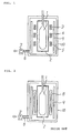
- Fig. 2 schematically shows a conventional apparatus for the production of the glass preform for the optical fiber.
- the apparatus comprises a vacuum vessel (10) in which a muffle tube (2) surrounding a fine particle deposited body (1) and a heating member (8) positioned outside the muffle tube (2) are placed and a thermal insulation (a heat shield) (9) is located between the heating element 8 and the wall of the vessel (10).
- the vessel (10) is further equipped with an evacuation port to which a vacuum pump (7) is connected through a vacuum line (6) so that the atmosphere inside the vessel can be vacuumed or reduced.
- the glass particle deposited body (1) inserted in the muffle tube (2) is vitrified there by heating it with the heating member (8).
- a vitrification temperature is usually in a range of 1550 to 1650° C
- the produced glass preform has a longitudinally non-uniform shape in its outer diameter as schematically shown in Fig. 4 which shows both end portions of the preform thicker and the central portion thereof thinner.
- existence of bubbles should be suppressed or eliminated.
- the outer diameter of the vitrified glass rod should be uniform.
- EP-A-0 523 692 discloses a method for producing a glass preform for an optical fiber.
- the method comprises heating a glass soot preform to remove gas at a temperature at which the soot preform is not vitrified and under reduced pressure.
- the preform is then further heated under reduced pressure to the vitrification temperature.
- the temperature may be increased stepwise punctuated by pauses at interim temperatures.
- a process for the production of a silica-based glass preform for an optical fiber comprising:
- the fine glass particle deposited body may be produced by any conventional process such as the VAD process or the OVD process.
- the atmosphere during the heating steps is continuously or successively evacuated in a conventional means such as a vacuum pump from an apparatus in which the heating steps are carried out.
- the atmosphere may comprise an inert gas, a halogen gas, a halogenated gas or a mixture thereof for a predetermined purpose such as dehydration, fluorine doping and the like, if necessary, according to the conventional knowledge, provided that the following specified pressure (degree of vacuum) and the following specified heating temperature are ensured.
- the body may be a composite which is produced by depositing the fine glass particles around a glass rod having an at least double waveguide structure of which refractive index is lower in its outer portion than its core portion.
- the first heating step is preferably continued in a temperature range of 1000 to 1300° C while the atmosphere in the furnace is evacuated with a vacuum pump until a pressure of the atmosphere (a degree of vacuum) reaches 10 Pa or less and more preferably 5 Pa or less.
- the second heating step is preferably carried out at a pressure of 10 Pa or less and more preferably 5 Pa or less with keeping the second heating temperature in a range of 1320 to 1480° C and more preferably 1350 to 1450° C for 10 to 120 minutes and more preferably 40 to 90 minutes while the evacuation is continued if necessary.
- a heating member which is located around a muffle tube and which heats the degassed body may comprise a plurality of heating elements which are located separately along a longitudinal direction of the body and which can control the heating temperature of degassed body portions independently from one another so that the heating elements can heat the degassed body portions to different temperatures along the length of the preform.
- the plurality of the heating elements may be so arranged that a lower portion of the degassed body is heated to a temperature equal to or higher than a temperature of an upper portion of the degassed body which is located above the lower portion.
- the third heating step is carried out at a pressure of 10 Pa or less and more preferably 5 Pa or less in a temperature range of 1490 to 1600° C and more preferably 1500 to 1550° C for 1 to 60 minutes and more preferably 5 to 20 minutes.
- the present inventors carried out the heating treatment of a fine glass particle deposited body in a reduced atmosphere while evacuated with the vacuum pump, and obtained a relationship between the first heating temperature and an attained degree of vacuum.
- a solid line in the graph of Fig. 5 shows such a relationship after 5 hours have been passed from the beginning of the heating.
- the attained degree of vacuum is 10 Pa or less.
- the body was heated to 1550° C so as to vitrify the body and then a number of bubbles contained in the vitrified body was obtained.
- the results are also shown in the graph of Fig. 5 with a broken line, which shows a relationship between the first heating temperature and the number of the bubbles finally confined in the vitrified body per one meter length of the body.
- the broken line when the first heating temperature is in a range of 1000 to 1300° C, nearly no bubble is left in the body.
- the first temperature is in the outside of such a specified range, the number of the contained bubbles is sharply increased.
- the vitrified glass preform with substantially no bubble that the glass body is heated to a temperature range of 1000 to 1300° C until the pressure inside the furnace reaches 10 Pa or less, and then the body is further heated to the higher temperature so as to vitrify the body.
- one more factor which is as important as the number of the bubbles contained in the preform is uniformity of an outer diameter of the glass preform along its length.
- the present inventors have found that there is a strong correlation of a retention time during which the degassed body is keep at the second heating temperature in a range of 1320 to 1480° C versus an outer diameter difference between around a middle portion and around a lower portion of the body (namely, "a diameter around the lower portion of the body” minus "a diameter around the central portion of the body") in the finally produced preform.
- Such a correlation is shown in Fig. 6.
- the inventors have further found a correlation between the second heating temperature and an outer diameter of a middle portion of the glass preform body after finally vitrified, and the correlation is shown in Fig. 7. This is because shrinkage along a radial direction of the body is larger at a higher temperature so that such a correlation is obtained.
- it is effective to carry out the second heating step so as to increase the temperature of the lower portion of the degassed body relative to the temperature of the upper portion of the degassed body and/or to decrease the temperature of the upper portion of the degassed body relative to the temperature of the lower portion of the degassed body in order to prevent the larger outer diameter of the lower portion of the glass body.
- one preferred embodiment according to the present invention may use a heating furnace as shown in Fig. 1 in which a heating member is divided into a plurality of heating elements (for example three heating elements 3, 4 and 5) located along a longitudinal direction of the degassed body and the heating temperature of each heating element is controlled independently from one another, so that the lower portion of the body may be heated to a temperature higher than a temperature to which the upper potion is heated.
- a heating furnace as shown in Fig. 1 a relationship, as shown in Fig. 8, was obtained as to the heating temperature difference between the lower heating element and the upper heating element versus the outer diameter difference between around the lower portion and the middle portion of the body. It has been found from the results that the diameter difference becomes less than 6 mm when the temperature of the lower heating element is higher than that of the upper heating element by 50° C or more.
- the third heating step is carried out in a range of 1490 to 1600° C which corresponds to the vitrification temperature of the glass particle deposited body. It has been found that a longer period of the third heating step than as required causes droop of the vitrified preform due to its weight since the glass is very soft at the third heating temperature. Therefore, the period of the third heating step should be as short as required, and thus the period is preferably in a range of 1 to 60 minutes and more preferably 5 to 20 minutes.
- the vitrified glass body having the uniform outer diameter is produced by relatively raising the heating temperature of the lower portion of the fine glass particle deposited body with using the heating member which is divided into the plurality of the independent heating elements.
- a fine silica glass particle deposited body (1) produced by the VAD process was heated to be vitrified according to the present invention.
- the body had outer diameter of 200 mm and a length of 1000 mm.
- the body was inserted in a muffle tube (2) located in the vacuum vessel (10) and heated to a temperature of 1200° C while the atmosphere was evacuated from the furnace.
- the pressure in the furnace was 20 Pa.
- the pressure was reduced to 3 Pa.
- a temperature of the upper heating element 3 was increased to 1330° C
- a temperature of the middle heating element 4 was increased to 1400° C
- a temperature of the lower heater was increased to 1470° C.
- Such an increased temperature condition was kept for one hour, and the pressure inside the furnace was constant at about 3 Pa during said one hour.
- the body was heated to 1550° C and kept at that temperature for 15 minutes, and the pressure inside the furnace was still constant at about 3 Pa. Then the body was cooled and observed.
- the body was of a so good quality that it had substantially no bubble over its whole length.
- the outer diameter of the body was substantially uniform such that it is 90 mm ⁇ 1.2 mm over its whole length.
- Example 2 The same fine glass particle deposited body as in Example 1 was inserted in a muffle tube 2 placed in the vacuum vessel as shown in Fig. 2, and the pressure inside the furnace was kept at 30 Pa and heated to a temperature of 1600° C for 30 minutes. Then, the body was cooled and taken out of the furnace. The body contained small bubbles having a size of 0.1 mm or less over its whole length and having a deformed form such that an outer diameter around the center portion was so thin as 76 mm, and the outer diameter around a lower portion was so thick as 90 mm.
- Example 2 The same fine glass particle deposited body as in Example 1 was inserted in the muffle tube 2 placed in the apparatus as shown in Fig. 1 which had been already preheated to a temperature of 800° C.
- the pressure inside the furnace attained to 5 Pa.
- the body is further heated so as to initiate the second heating step in which the upper heating element was set to 1320° C, the middle one to 1390° C and the lower one to 1470° C and such a different temperature condition was kept for one hour.
- the upper heating element was set to 1550° C, the middle one to 1525° C and the lower one to 1500° C and such a different increased temperature condition was kept for 30 minutes, and then cooled.
- the pressure inside the furnace was constant at 5 Pa.
- the produced glass preform was of a so good quality that it had substantially no bubble over its whole length.
- the outer diameter of the body was substantially uniform such that it is 90 mm ⁇ 0.8 mm over its whole length.
Landscapes
- Chemical & Material Sciences (AREA)
- Engineering & Computer Science (AREA)
- Chemical Kinetics & Catalysis (AREA)
- General Chemical & Material Sciences (AREA)
- Life Sciences & Earth Sciences (AREA)
- General Life Sciences & Earth Sciences (AREA)
- Geochemistry & Mineralogy (AREA)
- Manufacturing & Machinery (AREA)
- Materials Engineering (AREA)
- Organic Chemistry (AREA)
- Physics & Mathematics (AREA)
- Thermal Sciences (AREA)
- Manufacture, Treatment Of Glass Fibers (AREA)
- Glass Melting And Manufacturing (AREA)
Claims (5)
- Procédé de production d'une préforme de verre à base de silice pour une fibre optique, comprenant :(i) le dépôt de particules de verre fines sur une tige afin de former un corps (1),(ii) le chauffage du corps sous pression réduite à une première température afin de le dégazer,(iii) le chauffage du corps dégazé sous pression réduite à une seconde température qui est supérieure à la première température afin de lui faire subir un retrait, et(iv) le chauffage du corps ayant subi un retrait sous pression réduite à une troisième température qui est supérieure à la seconde température et qui provoque une vitrification des particules de verre fines afin de produire la préforme de verre ;
caractérisé en ce que l'étape de chauffage (iii) destinée à produire le retrait du corps est effectuée de telle manière que des parties différentes du corps, dans sa direction longitudinale, soient chauffées à des secondes températures différentes qui peuvent être régulées indépendamment les unes des autres, le corps étant orienté de façon à avoir une partie inférieure et une partie supérieure, la température de la partie inférieure étant supérieure à la température de la partie supérieure. - Procédé selon la revendication 1, dans lequel la première température est dans l'intervalle de 1000-1300°C, et l'étape de chauffage (ii) est effectuée tout en abaissant la pression jusqu'à ce que la pression atteigne 10 Pa ou moins.
- Procédé selon la revendication 1 ou 2, dans lequel l'étape de chauffage (iii) destinée au retrait du corps comprend le chauffage du corps à une température dans la gamme de 1320-1480°C à une pression de 10 Pa ou moins pendant 10-120 minutes.
- Procédé selon l'une quelconque des revendications précédentes, dans lequel l'étape de chauffage (iv) destinée à la vitrification des particules de verre fines comprend le chauffage du corps à une température dans l'intervalle de 1490-1600°C à une pression de 10 Pa ou moins pendant 1-60 minutes.
- Procédé selon l'une quelconque des revendications précédentes, dans lequel la tige est une tige de verre ayant une structure de guide d'ondes au moins double dont la périphérie a un indice de réfraction plus faible que son âme.
Applications Claiming Priority (2)
| Application Number | Priority Date | Filing Date | Title |
|---|---|---|---|
| JP5042774A JP2917729B2 (ja) | 1993-03-03 | 1993-03-03 | 光ファイバ母材の製造方法 |
| JP42774/93 | 1993-03-03 |
Publications (2)
| Publication Number | Publication Date |
|---|---|
| EP0613866A1 EP0613866A1 (fr) | 1994-09-07 |
| EP0613866B1 true EP0613866B1 (fr) | 1998-08-12 |
Family
ID=12645320
Family Applications (1)
| Application Number | Title | Priority Date | Filing Date |
|---|---|---|---|
| EP94103051A Expired - Lifetime EP0613866B1 (fr) | 1993-03-03 | 1994-03-01 | Procédé de fabrication d'une préforme en verre pour fibre optique |
Country Status (9)
| Country | Link |
|---|---|
| US (1) | US5693115A (fr) |
| EP (1) | EP0613866B1 (fr) |
| JP (1) | JP2917729B2 (fr) |
| KR (1) | KR940022178A (fr) |
| CN (1) | CN1051979C (fr) |
| AU (1) | AU672268B2 (fr) |
| CA (1) | CA2116701C (fr) |
| DE (1) | DE69412308D1 (fr) |
| TW (1) | TW272969B (fr) |
Families Citing this family (21)
| Publication number | Priority date | Publication date | Assignee | Title |
|---|---|---|---|---|
| US5656057A (en) * | 1995-05-19 | 1997-08-12 | Corning Incorporated | Method for drying and sintering an optical fiber preform |
| DE69512029T2 (de) * | 1995-05-22 | 1999-12-30 | Corning Inc | Verfahren zum Trocknen und Sintern einer Vorform für optische Fasern |
| JPH1011022A (ja) | 1996-06-18 | 1998-01-16 | Sharp Corp | 表示装置の駆動回路 |
| US6289698B1 (en) | 1996-08-02 | 2001-09-18 | Corning Incorporated | Method of making a fiber preform with increases in alumina concentration at radial distances |
| DE69800722T2 (de) * | 1997-05-30 | 2001-08-02 | Shinetsu Chemical Co | Verfahren zum Ziehen einer Glasvorform zu einem Stab |
| JPH1179773A (ja) * | 1997-09-08 | 1999-03-23 | Sumitomo Electric Ind Ltd | ガラス母材の製造方法及びその装置 |
| AU755861B2 (en) * | 1998-08-31 | 2003-01-02 | Sumitomo Electric Industries, Ltd. | Method of producing glass article and glass base material for optical fiber |
| KR100568894B1 (ko) * | 1998-10-21 | 2006-04-10 | 스미토모덴키고교가부시키가이샤 | 다공질 유리 모재 제조 장치 및 제조 방법 |
| KR100539869B1 (ko) * | 2002-08-29 | 2005-12-28 | 삼성전자주식회사 | 젤 튜브의 소결 장치와 이를 이용한 대구경 광섬유 모재의제조방법 |
| NL1024943C2 (nl) * | 2003-12-04 | 2005-06-07 | Draka Fibre Technology Bv | Werkwijze ter vervaardiging van een optische vezel. |
| KR100651528B1 (ko) | 2004-06-03 | 2006-11-29 | 삼성전자주식회사 | 광섬유의 수소 민감도를 감소하기 위한 방법 |
| KR100577491B1 (ko) * | 2004-06-28 | 2006-05-10 | 엘에스전선 주식회사 | 저손실 광섬유 및 그 제조방법 |
| US8020410B2 (en) * | 2007-11-15 | 2011-09-20 | Corning Incorporated | Methods for making optical fiber preforms and microstructured optical fibers |
| GB0800895D0 (en) * | 2008-01-18 | 2008-02-27 | Saint Gobain Quartz Plc | Heat treatment furnaces |
| US20100122558A1 (en) * | 2008-11-19 | 2010-05-20 | John Michael Jewell | Apparatus and Method of Sintering an Optical Fiber Preform |
| CN102531377B (zh) * | 2012-01-16 | 2014-05-21 | 宁波大学 | 一种用于制备硫系玻璃微结构光纤预制棒的设备及方法 |
| JP5560313B2 (ja) * | 2012-11-12 | 2014-07-23 | 株式会社フジクラ | 光ファイバ用母材の製造方法 |
| CN105753311B (zh) * | 2016-02-04 | 2018-08-07 | 长飞光纤光缆股份有限公司 | 一种光纤预制棒的脱气装置及方法 |
| JP7205216B2 (ja) * | 2018-12-25 | 2023-01-17 | 住友電気工業株式会社 | 光ファイバ用母材の製造方法 |
| CN113248131B (zh) * | 2021-05-31 | 2021-09-17 | 中天科技精密材料有限公司 | 光纤预制棒及其制造设备和制备方法 |
| CN115403265B (zh) * | 2022-09-19 | 2024-02-02 | 武汉烽火锐拓科技有限公司 | 一种光纤制造系统及制造方法 |
Family Cites Families (12)
| Publication number | Priority date | Publication date | Assignee | Title |
|---|---|---|---|---|
| US4586943A (en) * | 1983-10-20 | 1986-05-06 | Sumitomo Electric Industries, Ltd. | Method for the production of glass preform for optical fibers |
| AU586058B2 (en) * | 1985-12-27 | 1989-06-29 | Sumitomo Electric Industries, Ltd. | Method of making optical glass article |
| JP2559395B2 (ja) * | 1987-02-17 | 1996-12-04 | 住友電気工業株式会社 | 高純度透明ガラスの製造方法及び製造装置 |
| DE3711281C1 (de) * | 1987-04-03 | 1988-06-16 | Heraeus Schott Quarzschmelze | Verfahren zum Verglasen eines poroesen,aus Glasruss bestehenden Koerpers und Ofen zu dessen Durchfuehrung |
| US4789389A (en) * | 1987-05-20 | 1988-12-06 | Corning Glass Works | Method for producing ultra-high purity, optical quality, glass articles |
| JPH01224236A (ja) * | 1988-03-01 | 1989-09-07 | Furukawa Electric Co Ltd:The | 多孔質光ファイバ母材の透明ガラス化方法 |
| US5023692A (en) * | 1989-12-07 | 1991-06-11 | Harris Semiconductor Patents, Inc. | Power MOSFET transistor circuit |
| US5185020A (en) * | 1990-08-27 | 1993-02-09 | The Furukawa Electric Co., Ltd. | Method for manufacturing a silica-base material for optical fiber |
| JPH04260630A (ja) * | 1991-02-08 | 1992-09-16 | Sumitomo Electric Ind Ltd | 光ファイバ用母材の製造方法 |
| AU653411B2 (en) * | 1991-07-19 | 1994-09-29 | Sumitomo Electric Industries, Ltd. | Method for producing glass preform for optical fiber |
| GB9210327D0 (en) * | 1992-05-14 | 1992-07-01 | Tsl Group Plc | Heat treatment facility for synthetic vitreous silica bodies |
| JPH06348491A (ja) * | 1993-06-10 | 1994-12-22 | Sanyo Electric Co Ltd | Doループ実行時のオーバヘッドを最小化するデータ処理装置 |
-
1993
- 1993-03-03 JP JP5042774A patent/JP2917729B2/ja not_active Expired - Lifetime
-
1994
- 1994-02-03 TW TW083100917A patent/TW272969B/zh active
- 1994-02-25 AU AU56361/94A patent/AU672268B2/en not_active Ceased
- 1994-02-28 KR KR1019940003655A patent/KR940022178A/ko not_active Application Discontinuation
- 1994-03-01 CA CA002116701A patent/CA2116701C/fr not_active Expired - Fee Related
- 1994-03-01 DE DE69412308T patent/DE69412308D1/de not_active Expired - Lifetime
- 1994-03-01 EP EP94103051A patent/EP0613866B1/fr not_active Expired - Lifetime
- 1994-03-02 CN CN94102020A patent/CN1051979C/zh not_active Expired - Lifetime
- 1994-03-02 US US08/204,100 patent/US5693115A/en not_active Expired - Lifetime
Also Published As
| Publication number | Publication date |
|---|---|
| JPH06256035A (ja) | 1994-09-13 |
| CN1051979C (zh) | 2000-05-03 |
| DE69412308D1 (de) | 1998-09-17 |
| TW272969B (fr) | 1996-03-21 |
| EP0613866A1 (fr) | 1994-09-07 |
| KR940022178A (ko) | 1994-10-20 |
| CA2116701A1 (fr) | 1994-09-04 |
| US5693115A (en) | 1997-12-02 |
| AU5636194A (en) | 1994-09-08 |
| CN1096012A (zh) | 1994-12-07 |
| AU672268B2 (en) | 1996-09-26 |
| JP2917729B2 (ja) | 1999-07-12 |
| CA2116701C (fr) | 2003-12-30 |
Similar Documents
| Publication | Publication Date | Title |
|---|---|---|
| EP0613866B1 (fr) | Procédé de fabrication d'une préforme en verre pour fibre optique | |
| CA2049898C (fr) | Methode de production d'un materiau a base de verre siliceux | |
| EP0176263B1 (fr) | Fibre optique | |
| EP0626351A1 (fr) | Procédé de fabrication de préformes poreuses pour fibres optiques | |
| US4863501A (en) | Method of employing plasma for finishing start rods | |
| EP0523692B1 (fr) | Procédé de fabrication d'une préforme pour fibre optique | |
| CA2318414C (fr) | Appareil de fabrication de preformes pour fibres optiques et procede de retrecissement et d'obturation d'un tube traite par depot | |
| EP0228082B1 (fr) | Procédé de fabrication d'un article en verre optique | |
| EP0201937B1 (fr) | Procédé pour la fabrication d'une préforme en verre pour fibres optiques | |
| US6732549B1 (en) | Multi-pass sintering of a sol-gel body through a hot zone | |
| EP1188724A1 (fr) | Procédé de fabrication d'une préforme pour fibres optiques par un procédé tube-barre | |
| EP0612701B1 (fr) | Procédé de fabrication des préformés pour fibres optiques par dépÔt axial en phase vapeur | |
| JP2813752B2 (ja) | 光導波路プレフォームの製造方法 | |
| AU755861B2 (en) | Method of producing glass article and glass base material for optical fiber | |
| US6266980B1 (en) | Centerline protection using heavy inert gases | |
| US4761170A (en) | Method for employing plasma in dehydration and consolidation of preforms | |
| US6050108A (en) | Method for producing glass preform | |
| JP3895644B2 (ja) | 光ファイバ母材の多孔質スート体のガラス化方法 | |
| US20020178761A1 (en) | Method of low PMD optical fiber manufacture | |
| JP2836302B2 (ja) | ガラス物品の製造方法 | |
| GB2362645A (en) | Apparatus for producing glass preform | |
| JP2001247329A (ja) | 光ファイバ母材の製造方法 | |
| MXPA00011756A (en) | Method of making a glass preform |
Legal Events
| Date | Code | Title | Description |
|---|---|---|---|
| PUAI | Public reference made under article 153(3) epc to a published international application that has entered the european phase |
Free format text: ORIGINAL CODE: 0009012 |
|
| AK | Designated contracting states |
Kind code of ref document: A1 Designated state(s): DE FR GB IT NL SE |
|
| 17P | Request for examination filed |
Effective date: 19950124 |
|
| 17Q | First examination report despatched |
Effective date: 19970325 |
|
| GRAG | Despatch of communication of intention to grant |
Free format text: ORIGINAL CODE: EPIDOS AGRA |
|
| GRAG | Despatch of communication of intention to grant |
Free format text: ORIGINAL CODE: EPIDOS AGRA |
|
| GRAH | Despatch of communication of intention to grant a patent |
Free format text: ORIGINAL CODE: EPIDOS IGRA |
|
| GRAH | Despatch of communication of intention to grant a patent |
Free format text: ORIGINAL CODE: EPIDOS IGRA |
|
| GRAA | (expected) grant |
Free format text: ORIGINAL CODE: 0009210 |
|
| AK | Designated contracting states |
Kind code of ref document: B1 Designated state(s): DE FR GB IT NL SE |
|
| PG25 | Lapsed in a contracting state [announced via postgrant information from national office to epo] |
Ref country code: NL Free format text: LAPSE BECAUSE OF FAILURE TO SUBMIT A TRANSLATION OF THE DESCRIPTION OR TO PAY THE FEE WITHIN THE PRESCRIBED TIME-LIMIT Effective date: 19980812 Ref country code: IT Free format text: LAPSE BECAUSE OF FAILURE TO SUBMIT A TRANSLATION OF THE DESCRIPTION OR TO PAY THE FEE WITHIN THE PRESCRIBED TIME-LIMIT;WARNING: LAPSES OF ITALIAN PATENTS WITH EFFECTIVE DATE BEFORE 2007 MAY HAVE OCCURRED AT ANY TIME BEFORE 2007. THE CORRECT EFFECTIVE DATE MAY BE DIFFERENT FROM THE ONE RECORDED. Effective date: 19980812 Ref country code: FR Free format text: LAPSE BECAUSE OF FAILURE TO SUBMIT A TRANSLATION OF THE DESCRIPTION OR TO PAY THE FEE WITHIN THE PRESCRIBED TIME-LIMIT Effective date: 19980812 |
|
| REF | Corresponds to: |
Ref document number: 69412308 Country of ref document: DE Date of ref document: 19980917 |
|
| PG25 | Lapsed in a contracting state [announced via postgrant information from national office to epo] |
Ref country code: DE Free format text: LAPSE BECAUSE OF FAILURE TO SUBMIT A TRANSLATION OF THE DESCRIPTION OR TO PAY THE FEE WITHIN THE PRESCRIBED TIME-LIMIT Effective date: 19981113 |
|
| EN | Fr: translation not filed | ||
| NLV1 | Nl: lapsed or annulled due to failure to fulfill the requirements of art. 29p and 29m of the patents act | ||
| PLBE | No opposition filed within time limit |
Free format text: ORIGINAL CODE: 0009261 |
|
| STAA | Information on the status of an ep patent application or granted ep patent |
Free format text: STATUS: NO OPPOSITION FILED WITHIN TIME LIMIT |
|
| 26N | No opposition filed | ||
| REG | Reference to a national code |
Ref country code: GB Ref legal event code: IF02 |
|
| PGFP | Annual fee paid to national office [announced via postgrant information from national office to epo] |
Ref country code: GB Payment date: 20050223 Year of fee payment: 12 |
|
| PGFP | Annual fee paid to national office [announced via postgrant information from national office to epo] |
Ref country code: SE Payment date: 20050304 Year of fee payment: 12 |
|
| PG25 | Lapsed in a contracting state [announced via postgrant information from national office to epo] |
Ref country code: GB Free format text: LAPSE BECAUSE OF NON-PAYMENT OF DUE FEES Effective date: 20060301 |
|
| PG25 | Lapsed in a contracting state [announced via postgrant information from national office to epo] |
Ref country code: SE Free format text: LAPSE BECAUSE OF NON-PAYMENT OF DUE FEES Effective date: 20060302 |
|
| EUG | Se: european patent has lapsed | ||
| GBPC | Gb: european patent ceased through non-payment of renewal fee |
Effective date: 20060301 |