EP0612000A2 - Dispositif d'alimentation en originaux - Google Patents
Dispositif d'alimentation en originaux Download PDFInfo
- Publication number
- EP0612000A2 EP0612000A2 EP94102431A EP94102431A EP0612000A2 EP 0612000 A2 EP0612000 A2 EP 0612000A2 EP 94102431 A EP94102431 A EP 94102431A EP 94102431 A EP94102431 A EP 94102431A EP 0612000 A2 EP0612000 A2 EP 0612000A2
- Authority
- EP
- European Patent Office
- Prior art keywords
- sheet original
- supply means
- original
- sheet
- supply
- Prior art date
- Legal status (The legal status is an assumption and is not a legal conclusion. Google has not performed a legal analysis and makes no representation as to the accuracy of the status listed.)
- Withdrawn
Links
Images


Classifications
-
- G—PHYSICS
- G03—PHOTOGRAPHY; CINEMATOGRAPHY; ANALOGOUS TECHNIQUES USING WAVES OTHER THAN OPTICAL WAVES; ELECTROGRAPHY; HOLOGRAPHY
- G03G—ELECTROGRAPHY; ELECTROPHOTOGRAPHY; MAGNETOGRAPHY
- G03G15/00—Apparatus for electrographic processes using a charge pattern
- G03G15/60—Apparatus which relate to the handling of originals
Definitions
- the present invention relates to a sheet original supply apparatus for supplying a sheet original to a predetermined position such as a reading portion of an image forming apparatus such as a copying machine, a laser beam printer and the like and for resting such a sheet original on the predetermined position. Further, the present invention relates to a reading apparatus and an image forming apparatus.
- Fig. 26 shows an example of a conventional sheet original supply apparatus.
- a sheet original P is supplied from an original tray 413 to a platen glass 422, where an image on the sheet original is read by an optical system 421 of a copying machine, and then the sheet original is discharged onto a tray 423.
- a separation means 414, 415, supply rollers 416 for effecting regist correction, relay rollers 417, and an image tip end sensor Sl are arranged in order, and, by means of such supply means, the original is passed through the platen 422 from the right, during which the reading-through (in which the image is read while the sheet original is being moved) of the sheet original is performed to form the image.
- the sheet originals P are separated one by one by the separation means 414, 415.
- the skew-feed of the sheet original is corrected by abutting the separated sheet original against a nip between the supply rollers 416, since the rear portion of the sheet original is still remaining in the separation means 414, 415 and the separation roller 415 and the separation belt 414 are being rotated in directions shown by the arrows, respectively, as the sheet original is pulled by the supply rollers 416, the sheet original is subjected to a load, with the result that there arises slip between the supply rollers 416 and the original, thereby worsening the regist correction (i.e., causing the error in a sheet feeding amount of the sheet original fed by the supply rollers 416).
- a sheet feed path from the supply rollers (regist correction rollers) 416 to the image reading portion 422 becomes long because the relay rollers 417 must be positioned in such a path, with the result that it is feared that the regist-corrected sheet original becomes wrong (out of correct registration) in the path on the way.
- the present invention aims to eliminate the above-mentioned conventional drawbacks, and has an object to provide a sheet original supply apparatus which does not cause the discrepancy of an image.
- Another object of the present invention is to provide a sheet original supply apparatus in which skew-feed correction can positively be effected and a sheet original the skew-feed of which was corrected is fed to a reading position as it is.
- a sheet original supply apparatus comprising convey means for feeding a sheet original at a reading portion, and supply means arranged at an upstream side of the convey means and adapted to feed the sheet original to the convey means.
- convey means for feeding a sheet original at a reading portion
- supply means arranged at an upstream side of the convey means and adapted to feed the sheet original to the convey means.
- a distance between a reading start position at the reading portion and the supply means is selected to be greater than a maximum length of an available sheet original.
- a sensor is arranged between the supply means and the convey means and a relay supply means is arranged at an upstream side of the supply means, and a distance between the relay supply means and the sensor is selected to be greater than the maximum length of the available sheet original.
- separation supply means may be arranged at an upstream side of the relay supply means, and a distance between the separation supply means and the supply means is selected to be greater than the maximum length of the available sheet original.
- the present invention it is possible to prevent the inconvenience that a trailing end of the sheet original is left from the supply means (rollers and the like) while the sheet original is being read. That is to say, the restraint of the trailing end of the sheet original is released before the reading of the sheet original is started.
- the vibration of the sheet original due to the passing-through of the trailing end of the sheet original during the reading operation can be prevented, the discrepancy in the image reading does not occur.
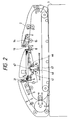
- an image forming apparatus (electrophotographic copying machine) is constituted by a main body 1 of the image forming apparatus and an RDF (re-circulating original document feeder) 2 as a sheet original supply apparatus. Further, the sheet supply apparatus may be provided with an optical reading system (reading apparatus).
- a first separation means for conveying a sheet material (sheet original) P to an image reading portion on a platen glass 3 from a left end of the platen glass 3, a first sheet original supply path (a), (b), (c), a second separation means for conveying the sheet original from a right end of the platen glass, and a second sheet original supply path (h), (i), (j) (see Fig. 4).
- the main body 1 of the image forming apparatus and the RDF 2 include a control means for switching reading modes between an original reading-stationary mode (in which the sheet original P is conveyed to a predetermined position on the platen 3 and is stopped there, and then an image on the sheet original is read while an optical system 301 of an image reading portion is being shifted in a direction A) and an original reading-through mode (in which the optical system 301 of the image reading portion is fixed at a predetermined position, and the image on the sheet original is read while conveying the sheet original at a predetermined speed), depending upon the size of the sheet original and/or a copying mode.
- an original reading-stationary mode in which the sheet original P is conveyed to a predetermined position on the platen 3 and is stopped there, and then an image on the sheet original is read while an optical system 301 of an image reading portion is being shifted in a direction A
- an original reading-through mode in which the optical system 301 of the image reading portion is fixed at a predetermined position, and the
- the sheet original P is conveyed by the first separation means and the first supply path (a), (b), (c), thereby forming an image.
- the sheet original P is conveyed by the second separation means and the second supply path (h), (i), (j), thereby forming an image.
- the RDF 2 has an original tray 4 at its upper portion, and a wide belt (convey means or convey rotary member) 7 wound around a drive roller 36 and a turn roller 37 is arranged below the original tray.
- the wide belt 7 is abutted against the platen 3 of the main body 1 of the copying machine and serves to convey the sheet original P from the original tray 4 to a predetermined position on the platen 3 and to convey the sheet original P from the platen 3 to the original tray 4.
- a pair of widthwise direction regulating plates 33 is slidably arranged on the original tray 4 for shifting movement in a widthwise direction of the sheet original P, so that the widthwise direction of the sheet original stack P rested on the original tray 4 is regulated by the regulating plates, thereby ensuring the supplying stability for the sheet original P and the registration of the sheet original when the sheet original is returned on the original tray 4.
- the widthwise direction regulating plates 33 include a jogging mechanism (which will be described later) for urging each sheet original P discharged on the original tray 4 against the original reference guide 33, thereby further improving the registration of the sheet originals.
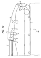
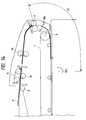
- the original tray 4 can be pivoted around a pivot pin 40 between a position shown in Fig. 1 and a position shown in Fig. 2 by an original tray lifting and lowering mechanism which will be described later.
- the sheet original stack P set on the original tray 4 is regulated by the protruded stopper 21 not to shift downstreamly.
- a first separation portion comprising a convey roller 38 and a separation belt 6 which constitute the separation portion is arranged downstream of the stopper 21, which roller and belt are rotated in directions shown by the arrows, respectively, to separate the sheet originals P fed from the original tray 4 one by one and to convey the separated sheet original downstreamly.
- a weight 20 arranged above the stopper 21 is lowered by a weight solenoid 109 (Fig. 5) to pinch the sheet original stack P between the weight and the supply roller 5, thereby enhancing the supplying force of the supply roller 5 when the number of the sheet originals P on the original tray 4 is decreased so that the sheet original P cannot be fed only by the supplying force of the supply roller 5.
- the original supply path (a), (b), (c) extends from the separation portion 6, 38 to the platen 3 (Fig. 4), which original supply path is curved to be connected to the convey path on the platen 3 to direct the sheet original onto the platen 3.
- inlet sensors 23a, 23b which are optical sensors of permeable type for detecting the presence/absence of the sheet original P on the original tray 4 are arranged in the proximity of the sheet supply roller 5.
- a large roller 10 is arranged at the left portion of the body of the RDF 2, and an original discharge path (e), (f) extending from the platen 3 to the original tray 4 through the periphery of the large roller 10 is provided (Fig. 4). Further, an original reverse rotation path (l) (Fig. 4) for reversely rotating or inverting the sheet original is branched from the original discharge path (e), (f) above the large roller 10, and a downstream end of the reverse rotation path (l) is jointed to the original supply path (b). Relay rollers 44 and discharge rollers 11 are arranged at a downstream side of the original discharge path (f) so that the sheet original P conveyed through the original discharge path (e), (f) is returned onto the sheet original stack P on the original tray 4.
- the wide belt 7 disposed on the platen 3 serves to convey the sheet original P to the predetermined position on the platen 3 and to stop it there, and to discharge the sheet original from the platen 3 after the image on the sheet original is read.
- a supply roller 9 is disposed at a junction between the original supply path (a), (b), (c) and the original reverse rotation path (l), which supply roller 9 serves to form a loop in the sheet original to correct the skew-feed of the sheet original P.
- Reverse rotation sensors 25a, 25b which are optical sensors of permeable type for detecting leading and trailing ends of the sheet original P are arranged in the proximity of the downstream side of the supply roller 9 so that the sheet original P passed through either the original supply path (a), (b), (c) or the original reverse rotation path (l) can be detected.
- regist sensors 39a, 39b which are optical sensors of permeable type for detecting the trailing end of the sheet original P is arranged at a downstream side of the supply roller 9.
- Reverse rotation sensors 26a, 26b which are optical sensors of permeable type for detecting the sheet original P discharged from the platen 3 are arranged below the large roller 10 in the original discharge path (e), (f), and discharge sensors 27a, 27b which are optical sensors of permeable type for detecting the passage of the sheet original P passed through the original discharge path (f) and to be discharged onto the original tray 4 are arranged in the original discharge path (f) between the large roller 10 and the discharge rollers 11.
- a reverse rotation flapper 34 for switching a path is disposed in a portion branched from the original discharge path (e), (f) to the original reverse rotation path (l), which flapper can be pivoted between a position shown by the solid line in Fig. 5 and a position shown by the dot and chain line by ON/OFF of a reverse rotation flapper solenoid 110 (Fig. 5) to switch the path.
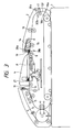
- the second original separation means for convey the sheet original to the image reading portion on the platen 3 from the right of the platen 3, and the second original supply path (h), (i), (j) (Fig. 4) are arranged at the right portion of the body of the RDF 2.
- the original tray 4 is shifted between the upper limit position shown in Fig. 1 and the lower limit position shown in Fig. 2 in response to the upper and lower pivotal movement of the original tray 4 which will be described later.
- a second semi-circular sheet supply roller 8, and a convey roller 15 and a separation belt 14 which constitute a second separation portion are arranged adjacent to the original tray 4.
- These elements 8, 15, 14 are rotated in directions shown by the arrows to separate the sheet originals P fed from the original tray 4 one by one and to convey the separated sheet original downstreamly.
- the stopper 21 and a short arm 63 integrally formed with the stopper are pivotable around a pivot pin 54, and a pin of the short arm 63 is engaged by a recessed portion of an operation member 59 so that, when the operation member 59 is rotated in a clockwise direction, the stopper 21 is shifted to a position shown by the dot and chain line.
- the operation member 59 an intermediate portion of which is pivotally mounted on a pivot pin is biased toward an anti-clockwise direction by a tension spring 64 and the rotation of the operation member 59 is regulated by a stopper 57.
- a lower end of the operation member 59 is connected to the stopper solenoid 108 via a connecting member 58.
- the original tray 4 is shifted to the upper limit position or the lower limit position depending upon the size of original rested on the original tray and/or the input condition of the image forming apparatus.
- the tray 4 reaches the lower limit position, the sheet original stack P rested on the original tray 4 is bundle-conveyed toward the second separation means 14, 15 by a predetermined distance by the above-mentioned stopper 21 of the tray 4.
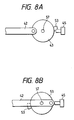
- a stopper slider 41 is shifted along guides 60, 61 (Fig. 6) formed on the tray 4 via rollers 46 by a rotation of an eccentric cam 43 connected to a link 42 (see Figs. 7 and 8).
- a flag 53 is formed on the eccentric cam 43 mounted on a shaft 57, and a sensor 45 of permeable type is associated with the cam to detect the flag for determining a home position (Figs. 6 and 8).
- a sheet original stopper 19 is pivoted upwardly around a pivot pin 31 by the original stopper solenoid 111 (Fig. 5), so that the sheet original stack P bundle-conveyed by the bundle convey means can be received.
- the bundle-conveyed sheet original stack P is always conveyed to a position (Fig. 3) where the presence of the sheet original stack is detected by optical sensors 28a, 28b of permeable type for detecting the presence/absence of the sheet original arranged at an upstream side of the proximity of the second separation means.
- the sheet original stopper 19 is rested on the sheet original stack P.
- the second separation means 14 there are arranged relay rollers (sheet supply means) 16, and second supply rollers (rotary members, regist convey means or skew-feed correction rollers) 17 are arranged at a downstream side of the relay rollers 16.
- the second supply rollers 17 serve to form a loop in the sheet original which has reached the rollers 17, thereby correcting the skew-feed of the sheet original P.
- Second sheet supply sensors 30a, 30b which are optical sensors of permeable type for detecting the leading and trailing ends of the sheet original P are arranged at an upstream side of the proximity of the second supply rollers 17.
- Optical sensors (sheet material detection means) 18a, 18b of permeable type for detecting a tip end position of the sheet original P are arranged in the second sheet supply path (j).
- the timing control for the sheet material on which the image is formed in the image forming apparatus is effected by these image tip end sensors 18a, 18b.
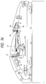
- a distance l1 between the separation portion 14, 15 and the supply rollers 17 along the second original convey path (h), (i), a distance l2 between the relay rollers 16 and the image tip end sensor 18 along the convey path (i), (j) and a distance l3 between the supply roller 17 and the fixed position of the optical system 301 of the image forming apparatus 1 in the reading-through mode along the convey path (j), (k) are selected to be greater than the size (for example, LTR 216 mm) of the sheet original having the maximum length among the sheet originals which can be conveyed in the second original convey path.
- the separation portion 14, 15 is also referred to as reversible rotary members (roller or belt), or feed roller and return roller, or separation supply means.
- the separation portion 14, 15, supply rollers 17, relay rollers 16 and the image tip end sensor 18 are arranged to satisfy a relation " distances l1, l2, l3 > 216 mm " and such positional relation is referred to as a convey load avoiding means (construction).
- a convey load avoiding means construction
- the RDF 2 of the present invention supplies the sheet original from the first sheet supply path.
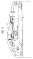
- Figs. 10 to 14 show a condition that the sheet originals P on the tray 4 are supplied through the original supply path (second original supply path) in the reading-through mode in detail.
- Fig. 11 shows a condition that the sheet original P is being conveyed by the relay rollers 16.
- the separation portion 14 is not driven.
- the separation portion applies the load to the sheet original which is being conveyed by the relay rollers 16.
- Fig. 12 shows a condition that the tip end of the preceding sheet original (first sheet original) P was reached to the supply rollers 17 (now stopped) so that the tip end of the sheet original P is abutted against the nip between the supply rollers 17 while forming a predetermined loop (to perform the registration of the tip end of the sheet original P).
- distance l1 between the second separation portion 14, 15 and the supply rollers 17 is selected to be greater than the size of the sheet original having the maximum length among the sheet originals which can be conveyed through the second supply path, when the tip end of the sheet original P is abutted against the nip between the sheet supply rollers 17, since the trailing end of the sheet original P has already been left from the second separation portion 14, 15, the above-mentioned load does not act on the sheet original, and, thus, the regist correction (skew-feed correction) can surely be effected. Thereafter, while the sheet original is being conveyed, the load of the separation portion does not act on the sheet original.
- Fig. 13 shows a condition that the trailing end of the registrated preceding sheet original P was passed through the relay rollers 16 and the tip end of the sheet original P is conveyed by the supply rollers 17 by a predetermined amount not to reach the image tip end sensor 18 and the sheet original is waiting there. Such waiting continues while the preceding sheet original is being treated. By waiting the sheet original in front of the platen, the high speed treatment can be achieved.
- the supply rollers 17 are driven by a motor 104 at the same speed as that of the relay rollers 16 in synchronous with the latter by engaging or applying a clutch 115 (the drive portion will be described fully in connection with Fig. 5).
- the distance l2 between the relay rollers 16 and the image tip end sensor 18 is selected as mentioned above, even when the trailing end of the sheet original P leaves the relay rollers 16, the tip end of the sheet original does not yet reach the image tip end sensor 18. That is to say, since the timing of the image tip end in the reading-through mode is selected on the basis of a time when the tip end of the sheet original reaches the image tip end sensor 18, the distance l2 is required to avoid the load of the relay rollers 16 on the sheet original P and to convey the sheet original stably and correctly (without any slip) only by the supply rollers 17. Incidentally, when the sheet original is stopped in Fig.
- the trailing end of the sheet original may be pinched between the relay rollers 16 and the trailing end of the sheet original may be left from the relay rollers 16 before the tip end of the sheet original reaches the image tip end sensor 18.
- the condition shown in Fig. 13 is more preferable in consideration of the convey safety. That is to say, the tip end of the sheet original may be stopped in front of the image tip end sensor 18.
- Fig. 14 shows a condition that the sheet original is re-conveyed from the stable waiting condition (left from the nip between the rollers 16) and is being conveyed to the fixed optical system 301 along the platen 3.
- a belt motor 102 By driving the supply rollers 17 by a belt motor 102 via the disengaged clutch 115 and an engaged clutch 116 (Fig.
- the reading of the image is started after the trailing end of the sheet original P leaves the supply rollers 17, with the result that, in the reading-through mode, it is possible to prevent the discrepancy in the image due to the load fluctuation generated when the trailing end of the sheet original leaves the supply rollers 17.
- the sheet original is conveyed through the discharge path starting from the left end of the platen and is discharged onto the sheet original stack P on the tray 4.
- the distance l3 may be shorter than the maximum size of the sheet original. That is to say, when the tip end of the sheet original reaches the belt 7, the rollers 17 may be separated from each other.
- Fig. 5 shows a drive system including motors and solenoids for driving the rollers and flappers.
- a first separation motor 100 serves to drive the convey roller 38 and separation belt 6 (separation portion) in the directions shown by the arrows in Fig. 1.
- a belt motor 102 serves to drive the drive roller 37 for driving the wide belt 7 and the supply rollers 17, and the rotation of the drive roller 37 is transmitted to the turn roller 36 via the wide belt 7. Further, a brake 112 is provided on a motor shaft of the belt motor 102 to ensure the stop position of the wide belt 7.
- a reverse rotation motor 101 serves to drive the large roller 10 and the discharge rollers 11.
- a second separation roller 103 serves to drive the convey roller 15 and the separation belt 14 in directions shown by the arrows in Fig. 1.
- a motor 104 serves to drive the second supply rollers 17 and the relay rollers 16.
- a third clutch 115 and a fourth clutch 116 are provided so that the second supply rollers 17 can be driven by either the motor 104 or the belt motor 102.
- Clock disks 100a, 101a, 102a, 103a, 104a each having a plurality of slits are mounted on respective motor shafts of the above-mentioned motors, and clock sensors 100b, 101b, 102b, 103b, 104b which are optical sensors of permeable type are associated with the corresponding clock disks to generate pulses by detecting the slits.
- clock sensors 100b, 101b, 102b, 103b, 104b which are optical sensors of permeable type are associated with the corresponding clock disks to generate pulses by detecting the slits.
- a stopper solenoid 108 serves to drive the stopper 21 in the up-and-down direction.
- the solenoid 108 is turned OFF, the stopper 21 is in a position shown in Fig. 1 to prevent the sheet original stack P on the original tray 4 from shifting downstreamly.
- the solenoid 108 is turned ON, the stopper 21 is retracted downwardly to open the convey path for the sheet original P (Fig. 6).
- a weight solenoid 109 serves to shift the weight 20 in the up-and-down direction.
- the solenoid 109 is turned OFF, the weight 20 is in a position shown in Fig. 1; whereas, when the solenoid 109 is turned ON, the weight 20 is shifted downwardly to urge the sheet original stack P against the sheet supply roller 5, thereby enhancing the conveying force of the sheet supply roller 5.
- An original stopper solenoid 111 serves to pivot the original stopper 19 in the up-and-down direction. When the solenoid 111 is turned OFF, the original stopper 19 is in a position shown by the solid line; whereas, when the solenoid 111 is turned ON, the original stopper is shifted upwardly to a position shown by the broken line.
- a tray rock motor 107 is attached to a support member 55 (Fig. 1) and a cam member 49 integral with a motor shaft of this motor is connected to a tray rock arm 48.
- a tray rock shaft 47 is engaged by a lower surface of the original tray 4.
- the tray rock shaft 47 is engaged by a tip end of the tray rock arm 48 and the other end of the tray rock arm 48 is engaged by a tray rock arm shaft 67 so that the tray rock arm 48 can be pivoted between positions shown in Figs. 1 and 2 by the rotation of the tray rock arm shaft 67, thereby rocking the original tray 4 around the fulcrum 40.
- An upper limit switch 51 serves to detect the fact that the original tray 4 reaches the upper limit position
- a lower limit switch 52 serves to detect the fact that the original tray 4 reaches the lower limit position.
- the rotation of the tray rock motor 107 is controlled by the detection of the upper and lower limit switches 51, 52 actuated by a projection 50 on the cam 49.
- a stopper slide motor 107 serves to shift the stopper 21 in a direction A in Fig. 2.
- the stopper 21 is returned to the original or initial position. Further, whenever the sheet original is discharged from the discharge rollers 11 onto the original tray 4, the stopper 21 urges the trailing end of the sheet original toward the second separation portion, thereby improving the registration of the sheet originals P on the original tray 4 in the original conveying direction (Figs. 15 and 16).
- Figs. 17A and 17B show the detailed construction of the partition member.
- a partition flag 119 and a partition lever 120 are coaxially arranged on an output shaft 105 of a partition member motor 105 (Fig. 5).
- the flag 119 is rotatably supported for a free rotation, and the partition lever 120 is secured to the output shaft 117 and serves to rotatingly drive the partition flag 119.
- the partition flag 119 has a cut-out at a portion of its periphery, and a partition member 22 formed from flexible material such as a polyester film, leaf spring or the like is secured to the periphery of the flag 119 to rotate together with the partition flag around the output shaft 117.
- a partition sensor 121 serves to detect the partition flag 119, thereby determining the position of the partition flag 119.
- the partition member 22 since the partition member 22 is flexible, when the partition member 22 is driven by the partition lever 120, the partition member 22 follows the surface condition of the sheet original stack to be entirely contacted with the upper surface of the sheet original stack P, thereby keeping the flat condition along the upper surface of the stack even when the sheet originals are decreased.
- the partition member 4 is always closely contacted with the upper surface of the sheet original stack P.
- the sheet originals P since the sheet original does not strike against the partition member 22, the sheet originals P can stably be re-stacked without worsening the re-supply of the sheet originals.
- a jogging guide 122 forming a part of the widthwise direction regulating plate 33a is retractably supported by the widthwise direction regulating plate 33a.
- Two link pins 126, 127 are provided at a side of the jogging guide 122 opposite to a side facing the sheet original stack, which link pins 126, 127 are connected to jogging links 123, 125, respectively.
- the other ends of the jogging links 123, 125 are connected to a jogging lever 129 via lever pins 130, 131, respectively. Further, the jogging lever 129 is connected to a jogging solenoid 132.
- the jogging guide 122 is operated to urge the sheet original stack P against the original reference guide 33.
- the jogging solenoid 132 is turned OFF, the jogging guide 122 is separated from the end face of the sheet original stack by a return spring 133. That is to say, whenever the sheet original P is re-stacked on the original tray 4, by repeating the ON/OFF operation of the jogging solenoid 132, the sheet original P is positively urged against the original reference guide 33, thereby enhancing the registration of the sheet originals P on the original tray 4.
- a slide volume (not shown) is connected to the widthwise direction regulating plate 33a, so that the size information of the sheet original in the widthwise direction can be obtained on the basis of the movement of the widthwise direction regulating plate 33a.
- a sensor 68 for detecting the length of the sheet original is provided at the rear end of the original tray 4.
- a sheet length detection sensor 68 (for example, of reflection type) serves to judge whether the size of the sheet original is greater than the LTR size (216 mm) or not.
- the sheet originals stacked on the original tray 4 are supplied by the first separation means 6, 38.
- the size information of the sheet original in the widthwise direction is obtained by the slide volume shifted in synchronous with the widthwise direction regulating plate 33a, with the result that it is judged whether the size of the sheet original is A4 size or LTR size or not. If A4 size or LTR size, the original tray 4 is lowered to satisfy the requirements that the sheet originals can be supplied by the second separation means 14, 15. Further, it is judged whether the sheet originals should be supplied by the first separation means or the second separation means on the basis of the image formation mode inputted to the image forming apparatus. If the size of the sheet original is other than A4 size or LTR size, the sheet originals are supplied by the first separation means.
- the above-mentioned the reference regarding the size of the sheet original is merely an embodiment of the present invention, and, thus, the reference value of the sheet size can be selected optionally.
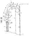
- Fig. 20 shows a second embodiment of the present invention.
- a distance l1 between a separation portion 514, 515 and a supply rollers 516 is shorter than 216 mm (LTR size).
- Sheet originals P on an original tray 504 are fed by a semi-circular roller 508 to the separation portion 514, 515, where the separation belt 514 and the separation roller 515 are rotated in directions shown by the arrows to separate the sheet originals one by one and to supply the separated sheet original.
- the supply rollers 516 also act as regist rollers for correcting the skew-feed of the sheet original P.
- such load releasing mechanism (convey load avoiding means) 500A comprises a link 513 pivotable around a fulcrum 511 and connected to the downstream roller at its one end, a tension spring for pulling the other end of the link 513, and a solenoid 512 connected to the other end of the link 513 so that the downstream roller can be lifted and lowered by the ON/OFF control of the solenoid 512.
- the link 513 is normally abutted against a stopper 510 so that the downstream roller is fixed at a predetermined position, thereby ensuring the constant gap amount between the separation belt 514 and the separation roller 515.
- the relay rollers 16 used in the first embodiment can be omitted, thus making the sheet supply apparatus small-sized.
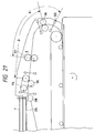
- Fig. 21 shows a third embodiment of the present invention. Also in this embodiment, since the left part of a sheet original supply apparatus is the same as that of the first embodiment, such left part is not shown and the explanation thereof will be omitted.
- sheet originals P on the original tray 504 are fed by the semi-circular roller 508 to the separation portion 514, 515, where the separation belt 514 and the separation roller 515 are rotated in directions shown by the arrows to separate the sheet originals one by one and to supply the separated sheet original.
- the supply rollers 516 also act as regist rollers for correcting the skew-feed of the sheet original P.
- a driven roller of a pair of relay rollers 517 is shiftable up to an upper position shown by the broken line by a load release mechanism (convey load avoiding means) 500B comprising a link 518 pivotable around a fulcrum 519 and connected to the driven roller at its one end, a tension spring 521 for pulling the other end of the link 518, and a solenoid 520 connected to the other end of the link 513.
- a load release mechanism convey load avoiding means
- the sheet original After the regist correction of the sheet original is finished, the sheet original starts to be conveyed by the supply rollers 516. Immediately before the tip end of the sheet original reaches a sensor 522, the driven roller of the pair of relay rollers 517 is shifted to the position shown by the broken line, thereby separating the relay rollers from each other.
- a distance l1 between the separation portion 514, 515 and the supply rollers 516 is greater than 216 mm (LTR size)
- a distance l2 between the relay rollers 517 and the image tip end sensor 522 may be smaller than 216 mm (LTR size) since the relay rollers 517 can be separated from each other as mentioned above.
- the distance l1 between the separation portion 514, 515 and the supply rollers 516 may be smaller than 216 mm (LTR size).
- a spring force of the tension spring 521 (Fig. 23) is selected to generate the (strong) nip pressure of the paired relay rollers 517 sufficient to avoid the influence of the load of the separation portion 514, 515 upon the trailing end of the sheet original. That is to say, the sheet original is pulled by the relay rollers with a conveying force greater than a force pulling the sheet original from the separation portion.
- the sheet feeding amount at the regist rollers is not influenced upon the load of the separation portion.
- the distance l2 between the relay rollers 517 and the image tip end sensor 522 can be smaller than 216 mm (LTR size), thereby making the sheet original supply apparatus compact and achieving the same technical effect as the aforementioned embodiment.
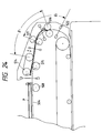
- a distance l1 between a separation portion 514, 515 and supply rollers 516 for effecting the regist correction and a distance l2 between relay rollers 517 and an image tip end sensor 522 are selected to be smaller than 216 mm (LTR size).
- Fig. 24 shows a condition that the sheet original separated by the separation portion 514, 515 and conveyed by the relay rollers 517 is abutted against the supply rollers (regist correction means) 516 to form a loop in the sheet original.
- An amount of the loop can be adjusted by controlling the sheet feeding amount of the relay rollers 517. When a predetermined amount of the loop is formed, the relay rollers 517 and the supply rollers 516 are rotated at the same speed, so that the sheet original is conveyed to the reading portion while maintaining the loop.
- the sheet original By conveying the sheet original while maintaining the loop in this way, even if the slip is generated between the relay rollers 517 and the sheet original, since such slip is absorbed by the loop in the sheet original, the sheet original can be conveyed by the supply rollers 516 without no slip, thereby preventing the out-of-registration. Further, the apparatus can be made small-sized.
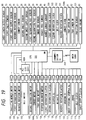
- Fig. 19 is a block diagram showing circuitry of a control device of the circulating original supply apparatus according to the present invention.
- the control circuit comprises a one-chip microcomputer (CPU) 201. Signals from various sensors are inputted to input ports of the microcomputer 201. Further, the slide volume for detecting the width of the sheet original is connected to an A/D conversion terminal of the microcomputer 210 so that the value of the slide volume can be detected continuously with 255 steps.
- CPU microcomputer
- various loads are connected to output ports of the microcomputer 201 via drivers.
- the belt motor 112 is connected to the output port of CPU 201 via conventional PLL circuit and a reversible driver.
- a rectangular wave signal having any frequency is inputted from a rectangular wave output terminal of the microcomputer 201 to the PLL circuit, so that the speed of the belt motor 112 and accordingly the peripheral speed of the wide belt 7 can be changed by changing the frequency of the signal.
- the communication of the control data is effected between the control device and the copying machine through a communication IC 202.
- the received data may be, for example, the reading-through speed data (v) from the copying machine, original convey mode (such as single-face mode, both-face mode or reading-through mode) data, original supply trigger, original exchange trigger, original discharge trigger and the like.
- the sending date may be, for example, the original supply/original exchange/original discharge operation completion signals, detected original size data, final original signal informing of the division of the original bundle, image tip end signal in the reading-through mode and the like.
- Fig. 25 shows an example of an image forming apparatus (copying machine) to which the present invention can be applied.
- An original resting platen glass 3, a light source 301, a lens system 908, a sheet supply portion 909, and an image forming portion 902 are arranged within a body 1 of the image forming apparatus.
- the sheet supply portion 909 includes cassettes 910, 911 removable with respect to the body 1 of the apparatus and adapted to contain sheets, and a deck 913 disposed on a pedestal 912.
- the image forming portion 902 includes a cylindrical photosensitive drum (image forming portion) 914 around which a developing device 915, a transfer charger 916, a separation charger 917, a cleaner 918 and a first charger 919 are arranged.
- a convey device 920, a fixing device 904 and discharge rollers 905 are arranged at a downstream side of the image forming portion 902.
- a sheet S is supplied from a cassette 910 or 911 or the deck 913.
- light emitted from the light source 301 and reflected by an original D rested on the platen glass 3 is sent to the photosensitive drum 914 through the lens system 908.
- the photosensitive drum 914 was previously charged by the first charger 919. Accordingly, when the light is illuminated on the photosensitive drum, an electrostatic latent image is formed on the drum. Then, the latent image is developed by the developing device 915 as a toner image.
- the skew-feed of the sheet S supplied from the sheet supply portion 909 is corrected by a pair of regist rollers 901, and the sheet is then sent to the image forming portion 902 at a predetermining timing.
- the toner image on the photosensitive drum 914 is transferred onto the sheet S by the transfer charger 916, and then the sheet to which the toner image was transferred is separated from the photosensitive drum 914 by the separation charger 917 by applying the charging polarity opposite to that of the transfer charger 917 to the sheet.
- the separated sheet S is then sent, by the convey device 912, to the fixing device 904, where the non-fixed toner image is permanently fixed to the sheet S. Then, the sheet S is discharged out of the image forming apparatus 1 by the discharge rollers 905.
- the image is formed on the sheet S supplied from the sheet supply portion 909 and then the sheet is discharged.
- the optical system or light source (reading means) 301 is positioned in the position shown in Fig. 25 (Fig. 1) in the reading-stationary mode, when the reading-through mode is selected, the light source is shifted to the right up to the reading position shown in Fig. 4.
- the present invention provides a sheet original supply apparatus comprising convey means for conveying a sheet original at a reading portion, and supply means arranged upstream of the convey means and adapted to send the sheet original to the convey means, wherein after the sheet original starts to be conveyed by the convey means and before the sheet original is read at the reading portion, the restraint of the sheet original by the supply means is released.
Landscapes
- Physics & Mathematics (AREA)
- General Physics & Mathematics (AREA)
- Sheets, Magazines, And Separation Thereof (AREA)
Applications Claiming Priority (2)
| Application Number | Priority Date | Filing Date | Title |
|---|---|---|---|
| JP55095/93 | 1993-02-19 | ||
| JP5509593 | 1993-02-19 |
Publications (2)
| Publication Number | Publication Date |
|---|---|
| EP0612000A2 true EP0612000A2 (fr) | 1994-08-24 |
| EP0612000A3 EP0612000A3 (en) | 1997-07-30 |
Family
ID=12989186
Family Applications (1)
| Application Number | Title | Priority Date | Filing Date |
|---|---|---|---|
| EP94102431A Withdrawn EP0612000A3 (en) | 1993-02-19 | 1994-02-17 | Original document feeder. |
Country Status (2)
| Country | Link |
|---|---|
| US (1) | US5645273A (fr) |
| EP (1) | EP0612000A3 (fr) |
Cited By (2)
| Publication number | Priority date | Publication date | Assignee | Title |
|---|---|---|---|---|
| EP0881546A1 (fr) * | 1997-05-29 | 1998-12-02 | Canon Kabushiki Kaisha | Dispositif pour alimentation en feuilles, et appareil pour lire des images et appareil de formation d'images avec un tel dispositif |
| US6076819A (en) * | 1996-12-28 | 2000-06-20 | Canon Kabushiki Kaisha | Sheet feeding apparatus, and image reading apparatus and image forming apparatus provided therewith |
Families Citing this family (12)
| Publication number | Priority date | Publication date | Assignee | Title |
|---|---|---|---|---|
| US6005687A (en) * | 1996-04-12 | 1999-12-21 | Ricoh Company, Ltd. | Imaging apparatus having different motors for separating and reading documents |
| JP3808747B2 (ja) * | 2001-10-19 | 2006-08-16 | ニスカ株式会社 | シート搬送装置及びシート給送装置 |
| JP2004299884A (ja) * | 2003-03-31 | 2004-10-28 | Fuji Photo Film Co Ltd | シート排出装置 |
| US7533878B2 (en) * | 2004-06-10 | 2009-05-19 | Lexmark International, Inc. | Printer media transport for variable length media |
| US7121546B2 (en) * | 2004-08-12 | 2006-10-17 | Lexmark International, Inc. | Speed mode for printer media transport |
| KR100608063B1 (ko) * | 2004-09-06 | 2006-08-02 | 삼성전자주식회사 | 화상형성장치의 급지장치 및 이를 적용한 화상형성장치 |
| JP4401986B2 (ja) * | 2005-03-10 | 2010-01-20 | 株式会社東芝 | 画像形成装置、シート搬送方法 |
| JP4429939B2 (ja) * | 2005-03-10 | 2010-03-10 | 株式会社東芝 | 画像形成装置 |
| JP4342461B2 (ja) * | 2005-03-10 | 2009-10-14 | 株式会社東芝 | 画像形成装置 |
| JP4468844B2 (ja) * | 2005-03-10 | 2010-05-26 | 株式会社東芝 | 画像形成装置、シート搬送方法 |
| JP4440146B2 (ja) * | 2005-03-10 | 2010-03-24 | 株式会社東芝 | 画像形成装置 |
| US20110187041A1 (en) * | 2010-01-29 | 2011-08-04 | Foxlink Image Technology Co., Ltd. | Sheet processing apparatus |
Citations (11)
| Publication number | Priority date | Publication date | Assignee | Title |
|---|---|---|---|---|
| US3885782A (en) * | 1973-12-06 | 1975-05-27 | Xerox Corp | Sheet feeder |
| JPS55163551A (en) * | 1979-06-06 | 1980-12-19 | Ricoh Co Ltd | Original feed method and its device |
| DE3212652A1 (de) * | 1981-04-11 | 1982-10-28 | Minolta Camera K.K., Osaka | Blatteinzugsvorrichtung fuer ein kopiergeraet o.dgl. |
| US4731637A (en) * | 1987-03-23 | 1988-03-15 | Xerox Corporation | Automatic "two-up" document registration and feeding for copiers |
| JPS63315429A (ja) * | 1987-06-17 | 1988-12-23 | Omron Tateisi Electronics Co | 自動原稿送り装置 |
| JPS63318538A (ja) * | 1987-06-22 | 1988-12-27 | Konica Corp | 原稿搬送装置 |
| JPH01187140A (ja) * | 1988-01-18 | 1989-07-26 | Konica Corp | 原稿搬送装置 |
| US4864366A (en) * | 1987-05-29 | 1989-09-05 | Ricoh Company, Ltd. | Automatic document feeder |
| US4896876A (en) * | 1987-06-22 | 1990-01-30 | Konica Corporation | Document feeding apparatus |
| JPH0361239A (ja) * | 1989-07-29 | 1991-03-18 | Konica Corp | 自動原稿搬送装置 |
| EP0551861A2 (fr) * | 1992-01-13 | 1993-07-21 | Canon Kabushiki Kaisha | Dispositif d'alimentation en originaux système de formation d'image muni d'un tel dispositif |
Family Cites Families (11)
| Publication number | Priority date | Publication date | Assignee | Title |
|---|---|---|---|---|
| EP0062798B1 (fr) * | 1981-03-31 | 1986-07-30 | Mita Industrial Co. Ltd. | Machine à copier électrostatique |
| JP2744233B2 (ja) * | 1987-01-14 | 1998-04-28 | キヤノン株式会社 | 原稿循環装置 |
| US4992827A (en) * | 1987-12-28 | 1991-02-12 | Canon Kabushiki Kaisha | Image forming apparatus |
| EP0333107B1 (fr) * | 1988-03-14 | 1993-12-08 | Canon Kabushiki Kaisha | Appareil d'amenée de documents |
| JPH0213531A (ja) * | 1988-06-29 | 1990-01-17 | Konica Corp | 原稿搬送装置 |
| US5118089A (en) * | 1989-09-05 | 1992-06-02 | Konica Corporation | Automatic document feeding apparatus |
| JP2700826B2 (ja) * | 1989-09-14 | 1998-01-21 | コニカ株式会社 | 自動原稿搬送装置 |
| US5132741A (en) * | 1989-11-05 | 1992-07-21 | Canon Kabushiki Kaisha | Sheet original feeding apparatus and image forming system |
| US5223905A (en) * | 1990-02-22 | 1993-06-29 | Konica Corporation | Automatic document conveying device |
| US5072923A (en) * | 1990-08-20 | 1991-12-17 | Xerox Corporation | User-friendly document input |
| JPH05188690A (ja) * | 1992-01-16 | 1993-07-30 | Mita Ind Co Ltd | 原稿自動給送装置 |
-
1994
- 1994-02-17 EP EP94102431A patent/EP0612000A3/en not_active Withdrawn
-
1995
- 1995-05-18 US US08/443,557 patent/US5645273A/en not_active Expired - Lifetime
Patent Citations (12)
| Publication number | Priority date | Publication date | Assignee | Title |
|---|---|---|---|---|
| US3885782A (en) * | 1973-12-06 | 1975-05-27 | Xerox Corp | Sheet feeder |
| JPS55163551A (en) * | 1979-06-06 | 1980-12-19 | Ricoh Co Ltd | Original feed method and its device |
| DE3212652A1 (de) * | 1981-04-11 | 1982-10-28 | Minolta Camera K.K., Osaka | Blatteinzugsvorrichtung fuer ein kopiergeraet o.dgl. |
| US4731637A (en) * | 1987-03-23 | 1988-03-15 | Xerox Corporation | Automatic "two-up" document registration and feeding for copiers |
| US4864366A (en) * | 1987-05-29 | 1989-09-05 | Ricoh Company, Ltd. | Automatic document feeder |
| JPS63315429A (ja) * | 1987-06-17 | 1988-12-23 | Omron Tateisi Electronics Co | 自動原稿送り装置 |
| JPS63318538A (ja) * | 1987-06-22 | 1988-12-27 | Konica Corp | 原稿搬送装置 |
| US4896876A (en) * | 1987-06-22 | 1990-01-30 | Konica Corporation | Document feeding apparatus |
| JPH01187140A (ja) * | 1988-01-18 | 1989-07-26 | Konica Corp | 原稿搬送装置 |
| JPH0361239A (ja) * | 1989-07-29 | 1991-03-18 | Konica Corp | 自動原稿搬送装置 |
| EP0551861A2 (fr) * | 1992-01-13 | 1993-07-21 | Canon Kabushiki Kaisha | Dispositif d'alimentation en originaux système de formation d'image muni d'un tel dispositif |
| EP0551862A2 (fr) * | 1992-01-13 | 1993-07-21 | Canon Kabushiki Kaisha | Système de formation d'image muni d'un appareil d'alimentation en originaux |
Non-Patent Citations (5)
| Title |
|---|
| PATENT ABSTRACTS OF JAPAN vol. 005, no. 042 (P-053), 20 March 1981 & JP 55 163551 A (RICOH CO LTD), 19 December 1980, * |
| PATENT ABSTRACTS OF JAPAN vol. 013, no. 154 (M-814), 14 April 1989 & JP 63 315429 A (OMRON TATEISI ELECTRONICS CO), 23 December 1988, * |
| PATENT ABSTRACTS OF JAPAN vol. 013, no. 159 (P-858), 18 April 1989 & JP 63 318538 A (KONICA CORP), 27 December 1988, * |
| PATENT ABSTRACTS OF JAPAN vol. 013, no. 473 (M-884), 26 October 1989 & JP 01 187140 A (KONICA CORP), 26 July 1989, * |
| PATENT ABSTRACTS OF JAPAN vol. 015, no. 215 (M-1119), 31 May 1991 & JP 03 061239 A (KONICA CORP), 18 March 1991, * |
Cited By (2)
| Publication number | Priority date | Publication date | Assignee | Title |
|---|---|---|---|---|
| US6076819A (en) * | 1996-12-28 | 2000-06-20 | Canon Kabushiki Kaisha | Sheet feeding apparatus, and image reading apparatus and image forming apparatus provided therewith |
| EP0881546A1 (fr) * | 1997-05-29 | 1998-12-02 | Canon Kabushiki Kaisha | Dispositif pour alimentation en feuilles, et appareil pour lire des images et appareil de formation d'images avec un tel dispositif |
Also Published As
| Publication number | Publication date |
|---|---|
| EP0612000A3 (en) | 1997-07-30 |
| US5645273A (en) | 1997-07-08 |
Similar Documents
| Publication | Publication Date | Title |
|---|---|---|
| US5351112A (en) | Original feeding apparatus and image forming system with it | |
| EP0031878A1 (fr) | Cassette pour feuilles de papier et appareil de copiage incorporant celle-ci | |
| US5132741A (en) | Sheet original feeding apparatus and image forming system | |
| US6021305A (en) | Sheet original conveying apparatus for duplex copying | |
| US5645273A (en) | Sheet original supply apparatus and image forming apparatus with it | |
| US6493113B1 (en) | Sheet conveying apparatus and image forming apparatus therewith | |
| US6256473B1 (en) | Image forming apparatus capable of copying original sheets having different sizes into sheets having different sizes | |
| JPH0318563A (ja) | 両面プリンタ | |
| US4873547A (en) | Sheet conveying apparatus | |
| US7420718B2 (en) | Sheet conveying apparatus, image reading apparatus and cam member driving device | |
| JP2003182880A (ja) | 画像形成装置 | |
| US5192976A (en) | Sheet original feeding apparatus with detachable auxiliary feeder | |
| JP3673618B2 (ja) | シート搬送装置およびこれを備えた画像形成装置 | |
| US7203454B2 (en) | Sheet post-process apparatus and waiting tray | |
| JP3913317B2 (ja) | 画像形成装置 | |
| KR100449092B1 (ko) | 용지 중간계류/반전부를 갖는 양면인쇄 가능한 화상형성장치 | |
| JP3902842B2 (ja) | シート搬送装置および、これを備えた画像読み取り装置,画像形成装置 | |
| JP2929482B2 (ja) | 原稿給送装置及びこの装置付き画像形成装置 | |
| JP3890133B2 (ja) | シート材搬送装置、及び該シート材搬送装置を備えた画像形成装置 | |
| JP2554476Y2 (ja) | 複写機における複写紙整合装置 | |
| JP3146455B2 (ja) | 原稿給送装置を備える画像形成装置 | |
| EP0881546B1 (fr) | Dispositif d'alimentation en feuilles pour un appareil de formation d'images | |
| JPH05310333A (ja) | 複写機の複写紙給紙機構 | |
| JP4086364B2 (ja) | 画像形成装置 | |
| JP3225387B2 (ja) | 自動原稿給送装置及び画像記録装置 |
Legal Events
| Date | Code | Title | Description |
|---|---|---|---|
| PUAI | Public reference made under article 153(3) epc to a published international application that has entered the european phase |
Free format text: ORIGINAL CODE: 0009012 |
|
| AK | Designated contracting states |
Kind code of ref document: A2 Designated state(s): DE ES FR GB IT NL SE |
|
| PUAL | Search report despatched |
Free format text: ORIGINAL CODE: 0009013 |
|
| AK | Designated contracting states |
Kind code of ref document: A3 Designated state(s): DE ES FR GB IT NL SE |
|
| 17P | Request for examination filed |
Effective date: 19971216 |
|
| 17Q | First examination report despatched |
Effective date: 19980212 |
|
| STAA | Information on the status of an ep patent application or granted ep patent |
Free format text: STATUS: THE APPLICATION IS DEEMED TO BE WITHDRAWN |
|
| 18D | Application deemed to be withdrawn |
Effective date: 20020829 |