EP0609012A2 - Méthode pour la fabrication d'une tête d'impression thermique par jet d'encre - Google Patents
Méthode pour la fabrication d'une tête d'impression thermique par jet d'encre Download PDFInfo
- Publication number
- EP0609012A2 EP0609012A2 EP94300395A EP94300395A EP0609012A2 EP 0609012 A2 EP0609012 A2 EP 0609012A2 EP 94300395 A EP94300395 A EP 94300395A EP 94300395 A EP94300395 A EP 94300395A EP 0609012 A2 EP0609012 A2 EP 0609012A2
- Authority
- EP
- European Patent Office
- Prior art keywords
- ink
- fill slot
- ink fill
- feed channel
- slot
- Prior art date
- Legal status (The legal status is an assumption and is not a legal conclusion. Google has not performed a legal analysis and makes no representation as to the accuracy of the status listed.)
- Granted
Links
- 238000000034 method Methods 0.000 title claims abstract description 36
- 238000004519 manufacturing process Methods 0.000 title description 7
- 239000000758 substrate Substances 0.000 claims abstract description 30
- 238000003754 machining Methods 0.000 claims abstract description 6
- 238000005299 abrasion Methods 0.000 claims abstract description 5
- 238000000608 laser ablation Methods 0.000 claims abstract description 3
- 238000005530 etching Methods 0.000 claims description 25
- XUIMIQQOPSSXEZ-UHFFFAOYSA-N Silicon Chemical compound [Si] XUIMIQQOPSSXEZ-UHFFFAOYSA-N 0.000 claims description 20
- 229910052710 silicon Inorganic materials 0.000 claims description 19
- 239000010703 silicon Substances 0.000 claims description 19
- 230000004888 barrier function Effects 0.000 claims description 17
- 238000005459 micromachining Methods 0.000 claims description 7
- 238000000059 patterning Methods 0.000 claims description 2
- 230000003247 decreasing effect Effects 0.000 claims 2
- 239000003989 dielectric material Substances 0.000 claims 2
- 239000010409 thin film Substances 0.000 claims 1
- 239000000463 material Substances 0.000 abstract description 5
- 238000001020 plasma etching Methods 0.000 abstract description 5
- 238000003486 chemical etching Methods 0.000 abstract description 4
- 238000010304 firing Methods 0.000 description 14
- 230000008569 process Effects 0.000 description 14
- 235000012431 wafers Nutrition 0.000 description 10
- 239000012530 fluid Substances 0.000 description 9
- 230000000873 masking effect Effects 0.000 description 5
- 238000007639 printing Methods 0.000 description 5
- 230000008901 benefit Effects 0.000 description 4
- 230000015572 biosynthetic process Effects 0.000 description 3
- 238000007641 inkjet printing Methods 0.000 description 3
- VYPSYNLAJGMNEJ-UHFFFAOYSA-N Silicium dioxide Chemical compound O=[Si]=O VYPSYNLAJGMNEJ-UHFFFAOYSA-N 0.000 description 2
- 238000013016 damping Methods 0.000 description 2
- 238000001035 drying Methods 0.000 description 2
- 238000010438 heat treatment Methods 0.000 description 2
- 230000006872 improvement Effects 0.000 description 2
- 238000004377 microelectronic Methods 0.000 description 2
- 230000004048 modification Effects 0.000 description 2
- 238000012986 modification Methods 0.000 description 2
- 230000004044 response Effects 0.000 description 2
- 229910052581 Si3N4 Inorganic materials 0.000 description 1
- 230000009471 action Effects 0.000 description 1
- 239000000654 additive Substances 0.000 description 1
- 230000000996 additive effect Effects 0.000 description 1
- 239000007864 aqueous solution Substances 0.000 description 1
- 230000009286 beneficial effect Effects 0.000 description 1
- 238000006243 chemical reaction Methods 0.000 description 1
- 150000001875 compounds Chemical class 0.000 description 1
- 239000004020 conductor Substances 0.000 description 1
- 239000013078 crystal Substances 0.000 description 1
- 230000007423 decrease Effects 0.000 description 1
- 230000001419 dependent effect Effects 0.000 description 1
- 238000001312 dry etching Methods 0.000 description 1
- 230000000694 effects Effects 0.000 description 1
- NBVXSUQYWXRMNV-UHFFFAOYSA-N fluoromethane Chemical compound FC NBVXSUQYWXRMNV-UHFFFAOYSA-N 0.000 description 1
- 230000005499 meniscus Effects 0.000 description 1
- 239000000203 mixture Substances 0.000 description 1
- 229910021421 monocrystalline silicon Inorganic materials 0.000 description 1
- 229910052756 noble gas Inorganic materials 0.000 description 1
- 150000002835 noble gases Chemical class 0.000 description 1
- 230000010355 oscillation Effects 0.000 description 1
- 238000002161 passivation Methods 0.000 description 1
- 229920002120 photoresistant polymer Polymers 0.000 description 1
- 238000005488 sandblasting Methods 0.000 description 1
- 235000012239 silicon dioxide Nutrition 0.000 description 1
- 239000000377 silicon dioxide Substances 0.000 description 1
- HQVNEWCFYHHQES-UHFFFAOYSA-N silicon nitride Chemical compound N12[Si]34N5[Si]62N3[Si]51N64 HQVNEWCFYHHQES-UHFFFAOYSA-N 0.000 description 1
- 239000000126 substance Substances 0.000 description 1
Images


Classifications
-
- B—PERFORMING OPERATIONS; TRANSPORTING
- B41—PRINTING; LINING MACHINES; TYPEWRITERS; STAMPS
- B41J—TYPEWRITERS; SELECTIVE PRINTING MECHANISMS, i.e. MECHANISMS PRINTING OTHERWISE THAN FROM A FORME; CORRECTION OF TYPOGRAPHICAL ERRORS
- B41J2/00—Typewriters or selective printing mechanisms characterised by the printing or marking process for which they are designed
- B41J2/005—Typewriters or selective printing mechanisms characterised by the printing or marking process for which they are designed characterised by bringing liquid or particles selectively into contact with a printing material
- B41J2/01—Ink jet
- B41J2/135—Nozzles
- B41J2/14—Structure thereof only for on-demand ink jet heads
- B41J2/14016—Structure of bubble jet print heads
- B41J2/14032—Structure of the pressure chamber
- B41J2/1404—Geometrical characteristics
-
- B—PERFORMING OPERATIONS; TRANSPORTING
- B41—PRINTING; LINING MACHINES; TYPEWRITERS; STAMPS
- B41J—TYPEWRITERS; SELECTIVE PRINTING MECHANISMS, i.e. MECHANISMS PRINTING OTHERWISE THAN FROM A FORME; CORRECTION OF TYPOGRAPHICAL ERRORS
- B41J2/00—Typewriters or selective printing mechanisms characterised by the printing or marking process for which they are designed
- B41J2/005—Typewriters or selective printing mechanisms characterised by the printing or marking process for which they are designed characterised by bringing liquid or particles selectively into contact with a printing material
- B41J2/01—Ink jet
- B41J2/135—Nozzles
- B41J2/14—Structure thereof only for on-demand ink jet heads
- B41J2/14016—Structure of bubble jet print heads
- B41J2/14145—Structure of the manifold
-
- B—PERFORMING OPERATIONS; TRANSPORTING
- B41—PRINTING; LINING MACHINES; TYPEWRITERS; STAMPS
- B41J—TYPEWRITERS; SELECTIVE PRINTING MECHANISMS, i.e. MECHANISMS PRINTING OTHERWISE THAN FROM A FORME; CORRECTION OF TYPOGRAPHICAL ERRORS
- B41J2/00—Typewriters or selective printing mechanisms characterised by the printing or marking process for which they are designed
- B41J2/005—Typewriters or selective printing mechanisms characterised by the printing or marking process for which they are designed characterised by bringing liquid or particles selectively into contact with a printing material
- B41J2/01—Ink jet
- B41J2/135—Nozzles
- B41J2/16—Production of nozzles
- B41J2/1601—Production of bubble jet print heads
- B41J2/1603—Production of bubble jet print heads of the front shooter type
-
- B—PERFORMING OPERATIONS; TRANSPORTING
- B41—PRINTING; LINING MACHINES; TYPEWRITERS; STAMPS
- B41J—TYPEWRITERS; SELECTIVE PRINTING MECHANISMS, i.e. MECHANISMS PRINTING OTHERWISE THAN FROM A FORME; CORRECTION OF TYPOGRAPHICAL ERRORS
- B41J2/00—Typewriters or selective printing mechanisms characterised by the printing or marking process for which they are designed
- B41J2/005—Typewriters or selective printing mechanisms characterised by the printing or marking process for which they are designed characterised by bringing liquid or particles selectively into contact with a printing material
- B41J2/01—Ink jet
- B41J2/135—Nozzles
- B41J2/16—Production of nozzles
- B41J2/1621—Manufacturing processes
- B41J2/1626—Manufacturing processes etching
- B41J2/1628—Manufacturing processes etching dry etching
-
- B—PERFORMING OPERATIONS; TRANSPORTING
- B41—PRINTING; LINING MACHINES; TYPEWRITERS; STAMPS
- B41J—TYPEWRITERS; SELECTIVE PRINTING MECHANISMS, i.e. MECHANISMS PRINTING OTHERWISE THAN FROM A FORME; CORRECTION OF TYPOGRAPHICAL ERRORS
- B41J2/00—Typewriters or selective printing mechanisms characterised by the printing or marking process for which they are designed
- B41J2/005—Typewriters or selective printing mechanisms characterised by the printing or marking process for which they are designed characterised by bringing liquid or particles selectively into contact with a printing material
- B41J2/01—Ink jet
- B41J2/135—Nozzles
- B41J2/16—Production of nozzles
- B41J2/1621—Manufacturing processes
- B41J2/1626—Manufacturing processes etching
- B41J2/1629—Manufacturing processes etching wet etching
-
- B—PERFORMING OPERATIONS; TRANSPORTING
- B41—PRINTING; LINING MACHINES; TYPEWRITERS; STAMPS
- B41J—TYPEWRITERS; SELECTIVE PRINTING MECHANISMS, i.e. MECHANISMS PRINTING OTHERWISE THAN FROM A FORME; CORRECTION OF TYPOGRAPHICAL ERRORS
- B41J2/00—Typewriters or selective printing mechanisms characterised by the printing or marking process for which they are designed
- B41J2/005—Typewriters or selective printing mechanisms characterised by the printing or marking process for which they are designed characterised by bringing liquid or particles selectively into contact with a printing material
- B41J2/01—Ink jet
- B41J2/135—Nozzles
- B41J2/16—Production of nozzles
- B41J2/1621—Manufacturing processes
- B41J2/1631—Manufacturing processes photolithography
-
- B—PERFORMING OPERATIONS; TRANSPORTING
- B41—PRINTING; LINING MACHINES; TYPEWRITERS; STAMPS
- B41J—TYPEWRITERS; SELECTIVE PRINTING MECHANISMS, i.e. MECHANISMS PRINTING OTHERWISE THAN FROM A FORME; CORRECTION OF TYPOGRAPHICAL ERRORS
- B41J2/00—Typewriters or selective printing mechanisms characterised by the printing or marking process for which they are designed
- B41J2/005—Typewriters or selective printing mechanisms characterised by the printing or marking process for which they are designed characterised by bringing liquid or particles selectively into contact with a printing material
- B41J2/01—Ink jet
- B41J2/135—Nozzles
- B41J2/16—Production of nozzles
- B41J2/1621—Manufacturing processes
- B41J2/1632—Manufacturing processes machining
- B41J2/1634—Manufacturing processes machining laser machining
Definitions
- the present application is related to application Serial No. , filed on [PD-190274], entitled “Compound Ink Feed Slot” and assigned to the same assignee as the present application.
- the present application is also related to application Serial No. , filed on even date herewith [PD-191123], entitled “Anisotropically Etched Ink Feed Slot in Silicon” and assigned to the same assignee as the present application.
- the present invention relates to thermal ink-jet printers, and, more particularly, to an improved printhead structure for introducing ink into the firing chambers.
- the art of thermal ink-jet printing it is known to provide a plurality of electrically resistive elements on a common substrate for the purpose of heating a corresponding plurality of ink volumes contained in adjacent ink reservoirs leading to the ink ejection and printing process.
- the adjacent ink reservoirs are typically provided as cavities in a barrier layer attached to the substrate for properly isolating mechanical energy to predefined volumes of ink.
- the mechanical energy results from the conversion of electrical energy supplied to the resistive elements which creates a rapidly expanding vapor bubble in the ink above the resistive elements.
- a plurality of ink ejection orifices are provided above these cavities in a nozzle plate and provide exit paths for ink during the printing process.
- thermal ink-jet printheads it is necessary to provide a flow of ink to the thermal, or resistive, element causing ink drop ejection. This has been accomplished by manufacturing ink fill channels, or slots, in the substrate, ink barrier, or nozzle plate.
- U.S. Patent 4,789,425 is directed to the "roof-shooter" configuration.
- this patent employs anisotropic etching of the substrate to form ink feed channels, it fails to address the issue of how to supply the volume of ink required at higher frequencies of operation.
- control of geometry, pen speed, or specific hydraulic damping control fails to address the issue of precisely matching the fluid impedance of every functional nozzle so that they all behave the same.
- an ink fill slot can be precisely manufactured in a substrate utilizing photolithographic techniques with chemical etching, plasma etching, or a combination thereof. These methods may be used in conjunction with laser machining, mechanical abrasion, electromechanical machining, or conventional etch to remove additional substrate material in desired areas.
- the improved ink-jet printhead of the invention includes a plurality of ink-propelling thermal elements, each ink-propelling element disposed in a separate drop ejection chamber defined by three barrier walls and a fourth side open to a reservoir of ink common to at least some of the elements, and a plurality of nozzles comprising orifices disposed in a cover plate in close proximity to the elements, each orifice operatively associated with an element for ejecting a quantity of ink normal to the plane defined by each element and through the orifices toward a print medium in pre-defined sequences to form alphanumeric characters and graphics thereon.
- Ink is supplied to the thermal element from an ink fill slot by means of an ink feed channel.
- Each drop ejection chamber may be provided with a pair of opposed projections formed in walls in the ink feed channel and separated by a width to cause a constriction between the plenum and the channel, and each drop ejection chamber may be further provided with lead-in lobes disposed between the projections and separating one ink feed channel from a neighboring ink feed channel.
- the improvement comprises forming the ink fill slot and the drop ejection chamber and associated ink feed channel on one substrate, in which the ink fill slot is partially formed by anisotropic etching of the substrate, employing chemical and/or plasma etching.
- the dimensions of the ink fill slot relative to the ink feed channel may be precisely controlled to aid in fluid tuning of the pen.
- the ink fill slot position can be controlled to within about 20 ⁇ m of the hydraulic limiting orifice (the area between the lead-in lobes) and can be modulated in depth as the slot extends to minimize air bubble trapping.
- the frequency of operation of thermal ink-jet pens is dependent upon the shelf or distance the ink needs to travel from the ink fill slot to the firing chamber, among other things. At higher frequencies, this distance, or shelf, must also be fairly tightly controlled. Through photochemical micromachining, this distance can be more tightly controlled and placed closer to the firing chamber. Etching can be from the frontside, backside, or both. A combination of etch processes can allow a range of profiles of the ink fill slot and shelf. This process can be used instead of, or in conjunction with, conventional "mechanical" slotting procedures to enhance performance or allow batch processing.
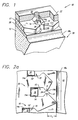
- FIG. 1 depicts a printing or drop ejecting element 10 , formed on a substrate 12 .
- FIGS. 2a and 2b depict three adjacent printing elements 10
- FIG. 3 depicts a portion of a printhead 13 comprising a plurality of such firing elements and shows a common ink fill slot 18 providing a supply of ink thereto.
- FIG. 3 depicts one common configuration of a plurality of firing elements, namely, two parallel rows of the firing elements 10 about a common ink fill slot 18
- other configurations employed in thermal ink-jet printing such as approximately circular and single row, may also be formed in the practice of the invention.
- Each firing element 10 comprises an ink feed channel 14 , with a resistor 16 situated at one end 14a thereof.
- the ink feed channel 14 and drop ejection chamber 15 encompassing the resistor 16 on three sides are formed in a layer 17 which comprises a photopolymerizable material which is appropriately masked and etched/developed to form the desired patterned opening.
- Ink (not shown) is introduced at the opposite end 14b of the ink feed channel 14 , as indicated by arrow "A" , from an ink fill slot, indicated generally at 18 .
- a nozzle, or convergent bore, 20 Associated with the resistor 16 is a nozzle, or convergent bore, 20 , located near the resistor in a nozzle plate 22 . Droplets of ink are ejected through the nozzle (e.g., normal to the plane of the resistor 16 ) upon heating of a quantity of ink by the resistor.
- a pair of opposed projections 24 at the entrance to the ink feed channel 14 provide a localized constriction, as indicated by the arrow "B" .
- the purpose of the localized constriction which is related to improve the damping of fluid motion of the ink, is more specifically described in U.S. Patent 4,882,595, and forms no part of this invention.
- Each such printing element 10 comprises the various features set forth above.
- Each resistor 16 is seen to be set in a drop ejection chamber 15 defined by three barrier walls and a fourth side open to the ink fill slot 18 of ink common to at least some of the elements 10 , with a plurality of nozzles 20 comprising orifices disposed in a cover plate 22 near the resistors 16 .
- Each orifice 20 is thus seen to be operatively associated with an resistor 16 for ejecting a quantity of ink normal to the plane defined by that resistor and through the orifices toward a print medium (not shown) in defined patterns to form alphanumeric characters and graphics thereon.
- Each firing element 10 is provided with a pair of opposed projections 24 formed in walls in the ink feed channel 14 and separated by a width "B" to cause a constriction between the ink fill slot 18 and the channel.
- Each firing element 10 may be provided with lead-in lobes 24a disposed between the projections 24 and separating one ink feed channel 14 from a neighboring ink feed channel 14' .
- the improvement comprises a precision means of forming the ink fill slot 18 and associated ink feed channel 14 on one substrate 12 .
- the ink fill slot 18 is extended to the pair of lead-in lobes 24a of each firing chamber, either at a constant distance from the entrance to the ink feed channel 14 , as shown in FIG. 2A, or at an equalized distance from the contour formed by the barrier layer 17 , as shown in FIG. 2B.
- the ink fill slot 18 is extended by means of extension 18a toward the lead-in lobes 24a , using precise etching, described in greater detail below, to controllably align the ink fill slot relative to the entrance to the ink feed channel 14 , indicated at "A" .
- the extended portion 18a of the ink fill slot 18 terminates at a constant distance from the center-line of the ink fill slot, very close to the lead-in lobes 24a .
- Use of precise etching, described below, permits a shorter shelf length, S L , to be formed; this shelf length is shorter than that of a presently commercially available pen used in Hewlett-Packard's DeskJet® printer, which extends to the edge of the ink fill slot 18 .
- the shorter shelf length permits firing at higher frequencies than presently commercially available pens. While the fluid impedance of the pen imparted to the ink is reduced compared to that in the commercially available pens, thereby resulting in improved performance, it is not substantially constant from one resistor heater 16 to the next.
- the extended portion 18a of the ink fill slot 18 follows the contour of the barrier wall 17 defining the lead-in lobes 24a , providing an equalized shelf length S L .
- This equalized shelf length provides a substantially constant fluid impedance to the ink in the pen, which results in improved pen performance.
- the extended portion 18a of the ink fill slot 18 is precisely manufactured in a substrate 12 utilizing. photolithographic techniques with chemical etching, plasma etching, or a combination thereof. These methods may be used in conjunction with laser micromachining, mechanical abrasion, or electromechanical machining to remove additional substrate material in desired areas.
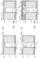
- Representative substrates for the fabrication of ink fill slots 18 in accordance with the invention comprise single crystal silicon wafers, commonly used in the micro-electronics industry. Silicon wafers with ⁇ 100> or ⁇ 110> crystal orientations are preferred. Three methods of ink fill slot fabrication consistent with this invention are detailed below. Typical resultant structures are shown in FIGS. 4C, 5C, and 6C.
- FIG. 4D is a cross-sectional view of a final structure in which ink is fed from the bottom of the substrate 12 .
- ⁇ 100> oriented silicon is employed as the substrate 12 .
- An oxide film 26 preferably silicon dioxide, is formed on both surfaces 12a , 12b of the substrate and is used to define the ink fill slot 18 to be etched.
- a silicon nitride film or other masking layer could be used, as detailed in the prior art.
- the dielectric 26 on the secondary surface 12b is patterned prior to formation of the ink fill slot 18 .
- the ink fill slot 18 comprises two portions.
- the first portion, 18' is formed by anisotropic etching. Since the anisotropic etching is in ⁇ 100> silicon, the angle formed is 54.74°, as is well-known.
- An aqueous solution of KOH, in a ratio of KOH:H2O of 2:1, heated to about 85°C is used for the anisotropic etching.
- This etchant etches ⁇ 100> silicon at a rate of about 1.6 ⁇ m/minute.
- the etching action is greatly reduced at a point where the ⁇ 111> planes intersect, and the ⁇ 100> bottom surface no longer exists.
- the anisotropic etching is stopped part way through the silicon wafer 12 , as shown in FIG. 4A.
- heater resistors 16 and electrical traces, or conductors, associated therewith, not shown are formed on the front surface 12a of the wafer, as shown in FIG. 4B.
- the process which is well-known, comprises forming appropriate layers and patterning them.
- the second portion, 18a , of the ink fill slot 18 is formed by a combination of isotropic and anisotropic etching, either by wet or dry processes, from the primary surface 12' . This process etches through the dielectric layer 26 on the primary surface 12a and into the silicon wafer 12 to connect with the previously-etched ink fill slot portion 18' .
- the resulting structure is shown in FIG. 4C.
- Dry etching in a plasma system may be used to define the second portion 18a .
- CF4 may be used, but other plasma etchants are also available for faster etching of the passivation while still protecting the silicon surface from overetch.
- etching step brings the ink fill slot 18 very close to the ink feed channel 14 .
- the proximity of the ink fill slot 18 to the ink feed channel 14 permits the printhead to be very responsive to demands for ink required at high drop ejection frequencies.
- Suitable masking is used to form the second portion 18a ; this masking may be configured to permit obtaining either the constant shelf length structure depicted in FIG. 2A or the equalized shelf length structure depicted in FIG. 2B.
- the structure is completed, as depicted in FIG. 4D, by the formation of the barrier layer 17 and the orifice plate 22 with nozzles 20 therein.
- FIGS. 5A-D represent a similar cross-sectional view of a final structure in which ink is fed from the bottom of the substrate 12 , which in this case is ⁇ 110> oriented.
- anisotropic etching may be used to etch part way or all the way through the substrate 10 , using the same etchant as for ⁇ 100>.
- the only difference in the process of this embodiment from that depicted in FIGS. 4A-D is the use of silicon of a different crystallographic orientation.
- the wafer is processed by known thermal ink-jet processes on the primary surface to form resistors 16 on the surface of the passivating layer 26 .
- a suitable photodefined masking layer (not shown) is then applied and imaged, exposing the area to be precision etched.
- masking layers include DuPont's VACREL and positive or negative photoresists, such as Hoechst AZ4906 or OCG SC900, respectively.
- only the.primary surface, 12a needs to be protected by the in-sulating dielectric layer 26 .
- Etching is done by well-documented dry processes utilizing CF4 + O2, SF6, or a mixture of fluorocarbon and noble gases to form portion 18a .
- the etch profile can be controlled by varying operating pressure and/or etcher configuration from reactive ion etching regimes (about 50 to 150 millitorr pressures and about 400 to 1,000 volts effective bias) anisotropic etching to high pressure planar etch regions (about 340 to 700 millitorr pressure and 0 to about 100 volts effective bias) isotropic etching or some subtle and beneficial combination of processes.
- the main part 18' of the ink feed slot 18 is then formed by micromachining, such as mechanical abrasion, e.g., sandblasting, or laser ablation, or electromechanical machining from the secondary surface 12b .
- the barrier layer 17 is generally formed prior to the final formation of the main part 18' , for reasons related to wafer handling (making the wafer stronger) and parts flow (avoiding returning the wafer to the clean room for processing).
- the frequency limit of a thermal ink-jet pen is limited by resistance in the flow of ink to the nozzle. Some resistance in ink flow is necessary to damp meniscus oscillation. However, too much resistance limits the upper frequency that a pen can operate.
- Ink flow resistance is intentionally controlled by a gap adjacent the resistor 16 with a well-defined length and width. This gap is the ink feed channel 14 , and its geometry is described elsewhere; see, e.g., U.S. Patent 4,882,595, issued to K.E. Trueba et al and assigned to the same assignee as the present application.
- the distance of the resistor 16 from the ink fill slot 18 varies with the firing patterns of the printhead.
- the entrance comprises a region between the orifice plate 22 and the substrate 12 and its height is essentially a function of the thickness of the barrier material 17 . This region has high impedance, since its height is small, and is additive to the well-controlled intentional impedance of the gap adjacent the resistor.
- the distance from the ink fill slot 18 to the entrance to the ink feed channel 14 is designated the shelf S L .
- the effect of the length of the shelf on pen frequency can be seen in FIG. 7: as the shelf increases in length, the nozzle frequency decreases.
- the substrate 12 is etched in this shelf region to form extension 18a of the ink fill slot 18 , which effectively reduces the shelf length and increases the cross-sectional area of the entrance to the ink feed channel 14 .
- the fluid impedance is reduced; both of the embodiments described above are so treated. In this manner, all nozzles have a more uniform frequency response.
- the advantage of the process of the invention is that the entire pen can now operate at a uniform higher frequency.
- each nozzle 20 had a different impedance as a function of its shelf length. With this variable eliminated, all nozzles have substantially the same impedance, thus tuning is simplified and when one nozzle is optimized, all nozzles are optimized.
- the pen had to be tuned for worst case nozzles, that is, the gap had to be tightened so that the nozzles lowest in impedance (shortest shelf) were not under-damped. Therefore, nozzles with a larger shelf would have greater impedance and lower frequency response.
- the curve shown in FIG. 7 has been derived from a pen ejecting droplets of about 130 pl volume.
- a shelf length of about 10 to 50 ⁇ m is preferred for high operating frequency.
- the curves are flatter and faster.
- FIGS. 2A and 2B depict the shelf length (S L ).
- the shelf is at a constant location on the die and therefore the S L dimension as measured from the entrance to the ink feed channel 14 varies somewhat due to resistor stagger, while in the latter case, the shelf length is equalized, in that it follows the contours of the barrier layer 17 .
- the precision etch of the primary surface of the silicon substrate in combination with the anisotropically etch through the secondary surface provides improved ink flow characteristics and is expected to find use in thermal ink-jet printheads.
- the precision etch may be done by a variety of isotropic etching processes.
Applications Claiming Priority (2)
| Application Number | Priority Date | Filing Date | Title |
|---|---|---|---|
| US9151 | 1993-01-25 | ||
| US08/009,151 US5387314A (en) | 1993-01-25 | 1993-01-25 | Fabrication of ink fill slots in thermal ink-jet printheads utilizing chemical micromachining |
Publications (3)
| Publication Number | Publication Date |
|---|---|
| EP0609012A2 true EP0609012A2 (fr) | 1994-08-03 |
| EP0609012A3 EP0609012A3 (fr) | 1994-09-14 |
| EP0609012B1 EP0609012B1 (fr) | 1997-05-28 |
Family
ID=21735887
Family Applications (1)
| Application Number | Title | Priority Date | Filing Date |
|---|---|---|---|
| EP94300395A Expired - Lifetime EP0609012B1 (fr) | 1993-01-25 | 1994-01-19 | Méthode pour la fabrication d'une tête d'impression thermique par jet d'encre |
Country Status (4)
| Country | Link |
|---|---|
| US (3) | US5387314A (fr) |
| EP (1) | EP0609012B1 (fr) |
| JP (1) | JP3535557B2 (fr) |
| DE (1) | DE69403352T2 (fr) |
Cited By (21)
| Publication number | Priority date | Publication date | Assignee | Title |
|---|---|---|---|---|
| WO1996032284A1 (fr) * | 1995-04-12 | 1996-10-17 | Eastman Kodak Company | Tetes d'impression monolithiques et leurs procedes de fabrication |
| WO1996032283A1 (fr) * | 1995-04-12 | 1996-10-17 | Eastman Kodak Company | Structure monolithique de tete d'impression et procede de fabrication faisant appel a la gravure humide anisotropique |
| EP0705706A3 (fr) * | 1994-10-06 | 1997-01-02 | Hewlett Packard Co | Système d'impression à jet d'encre |
| EP0705693A3 (fr) * | 1994-10-06 | 1997-01-08 | Hewlett Packard Co | Système d'impression à jet d'encre |
| EP0705694A3 (fr) * | 1994-10-06 | 1997-01-22 | Hewlett Packard Co | Système d'impression |
| EP0757940A2 (fr) * | 1995-08-09 | 1997-02-12 | Canon Kabushiki Kaisha | Tête d'enregistrement à jet de liquide et son procédé de fabrication ainsi qu'un appareil d'enregistrement à jet de liquide dans lequel est montée ladite tête d'enregistrement à jet de liquide |
| US5658471A (en) * | 1995-09-22 | 1997-08-19 | Lexmark International, Inc. | Fabrication of thermal ink-jet feed slots in a silicon substrate |
| EP0847860A2 (fr) * | 1996-12-13 | 1998-06-17 | Canon Kabushiki Kaisha | Procédé de fabrication d'une tête d'enregistrement à jet d'encre et tête d'enregistrement à jet |
| US5850241A (en) * | 1995-04-12 | 1998-12-15 | Eastman Kodak Company | Monolithic print head structure and a manufacturing process therefor using anisotropic wet etching |
| EP0921001A1 (fr) * | 1997-12-05 | 1999-06-09 | Canon Kabushiki Kaisha | Tête d'impression thermique à jet d'encre avec une impédance de canal d'écoulement de fluide |
| EP0841167A3 (fr) * | 1996-11-11 | 2000-03-08 | Canon Kabushiki Kaisha | Méthode de production d'un trou traversant, substrat silicon avec un trou traversant, dispositif utilisant un substrat méthode de production d'une tête d'impression à jet d'encre et tête d'impression à jet d'encre |
| US6143190A (en) * | 1996-11-11 | 2000-11-07 | Canon Kabushiki Kaisha | Method of producing a through-hole, silicon substrate having a through-hole, device using such a substrate, method of producing an ink-jet print head, and ink-jet print head |
| EP1225049A3 (fr) * | 1997-01-24 | 2002-08-07 | Seiko Epson Corporation | Tête d'enregistrement jet d'encre |
| EP1253626A2 (fr) * | 2000-07-21 | 2002-10-30 | Dai Nippon Printing Co., Ltd. | Technique de dessin a motifs fins |
| GB2384753A (en) * | 2002-01-31 | 2003-08-06 | Hewlett Packard Co | Methods and systems for forming slots in substrate |
| GB2384752A (en) * | 2002-01-31 | 2003-08-06 | Hewlett Packard Co | Slotted substrates and methods and systems for forming same |
| EP1559553A1 (fr) * | 2004-01-29 | 2005-08-03 | Hewlett-Packard Development Company, L.P. | Procédé de fabrication d'une tête d'impression par jet d'encre |
| WO2005123395A1 (fr) | 2004-06-17 | 2005-12-29 | Silverbrook Research Pty Ltd | Procede de modification du profil de surface d'un canal d'alimentation en encre dans une tete impression |
| US7051426B2 (en) | 2002-01-31 | 2006-05-30 | Hewlett-Packard Development Company, L.P. | Method making a cutting disk into of a substrate |
| EP2202076A2 (fr) | 2008-12-19 | 2010-06-30 | Canon Kabushiki Kaisha | Tête de décharge de liquide et procédé de fabrication de la tête de décharge de liquide |
| CN106903999A (zh) * | 2015-12-04 | 2017-06-30 | 精工爱普生株式会社 | 流道部件、液体喷射装置以及流道部件的制造方法 |
Families Citing this family (177)
| Publication number | Priority date | Publication date | Assignee | Title |
|---|---|---|---|---|
| US6190005B1 (en) * | 1993-11-19 | 2001-02-20 | Canon Kabushiki Kaisha | Method for manufacturing an ink jet head |
| US5808640A (en) * | 1994-04-19 | 1998-09-15 | Hewlett-Packard Company | Special geometry ink jet resistor for high dpi/high frequency structures |
| EP0678387B1 (fr) * | 1994-04-20 | 1998-12-02 | Seiko Epson Corporation | Dispositif d'enregistrement à jet d'encre et méthode de fabrication d'une tête à jet d'encre |
| US5666143A (en) * | 1994-07-29 | 1997-09-09 | Hewlett-Packard Company | Inkjet printhead with tuned firing chambers and multiple inlets |
| US5912685A (en) * | 1994-07-29 | 1999-06-15 | Hewlett-Packard Company | Reduced crosstalk inkjet printer printhead |
| FR2727648B1 (fr) * | 1994-12-01 | 1997-01-03 | Commissariat Energie Atomique | Procede de fabrication micromecanique de buses pour jets de liquide |
| DE69504024T2 (de) * | 1994-12-27 | 1999-03-25 | Agfa Gevaert Nv | Direkte elektrostatische Druckvorrichtung (DEP) mit einer Druckkopfstruktur mit einem maximalen Stromfluss von 50 microA zwischen der Steuerelektrode und der Abschirmelektrode |
| JP2914218B2 (ja) | 1995-05-10 | 1999-06-28 | 富士ゼロックス株式会社 | サーマルインクジェットヘッドおよび記録装置 |
| JP3386099B2 (ja) * | 1995-07-03 | 2003-03-10 | セイコーエプソン株式会社 | インクジェット式記録ヘッド用ノズルプレート、これの製造方法、及びインクジェット式記録ヘッド |
| US6183064B1 (en) | 1995-08-28 | 2001-02-06 | Lexmark International, Inc. | Method for singulating and attaching nozzle plates to printheads |
| JP3618960B2 (ja) * | 1996-05-13 | 2005-02-09 | キヤノン株式会社 | インクジェット記録ヘッド及び該ヘッドを搭載するインクジェット装置 |
| US5847737A (en) * | 1996-06-18 | 1998-12-08 | Kaufman; Micah Abraham | Filter for ink jet printhead |
| US5818478A (en) * | 1996-08-02 | 1998-10-06 | Lexmark International, Inc. | Ink jet nozzle placement correction |
| US5793393A (en) * | 1996-08-05 | 1998-08-11 | Hewlett-Packard Company | Dual constriction inklet nozzle feed channel |
| US5710070A (en) * | 1996-11-08 | 1998-01-20 | Chartered Semiconductor Manufacturing Pte Ltd. | Application of titanium nitride and tungsten nitride thin film resistor for thermal ink jet technology |
| US6158843A (en) * | 1997-03-28 | 2000-12-12 | Lexmark International, Inc. | Ink jet printer nozzle plates with ink filtering projections |
| JP3416467B2 (ja) * | 1997-06-20 | 2003-06-16 | キヤノン株式会社 | インクジェットヘッドの製造方法、インクジェットヘッドおよびインクジェットプリント装置 |
| US20090273632A1 (en) * | 1997-07-15 | 2009-11-05 | Silverbrook Research Pty Ltd | Printhead Integrated Circuit With Large Nozzle Array |
| US7468139B2 (en) * | 1997-07-15 | 2008-12-23 | Silverbrook Research Pty Ltd | Method of depositing heater material over a photoresist scaffold |
| US7287836B2 (en) * | 1997-07-15 | 2007-10-30 | Sil;Verbrook Research Pty Ltd | Ink jet printhead with circular cross section chamber |
| US6557977B1 (en) * | 1997-07-15 | 2003-05-06 | Silverbrook Research Pty Ltd | Shape memory alloy ink jet printing mechanism |
| AUPP653998A0 (en) * | 1998-10-16 | 1998-11-05 | Silverbrook Research Pty Ltd | Micromechanical device and method (ij46B) |
| US6712453B2 (en) * | 1997-07-15 | 2004-03-30 | Silverbrook Research Pty Ltd. | Ink jet nozzle rim |
| US7556356B1 (en) * | 1997-07-15 | 2009-07-07 | Silverbrook Research Pty Ltd | Inkjet printhead integrated circuit with ink spread prevention |
| US6513908B2 (en) * | 1997-07-15 | 2003-02-04 | Silverbrook Research Pty Ltd | Pusher actuation in a printhead chip for an inkjet printhead |
| US8117751B2 (en) * | 1997-07-15 | 2012-02-21 | Silverbrook Research Pty Ltd | Method of forming printhead by removing sacrificial material through nozzle apertures |
| US20090273641A1 (en) * | 1997-07-15 | 2009-11-05 | Silverbrook Research Pty Ltd | Printhead IC With Ink Supply Channel For Multiple Nozzle Rows |
| US20090278891A1 (en) * | 1997-07-15 | 2009-11-12 | Silverbrook Research Pty Ltd | Printhead IC With Filter Structure At Inlet To Ink Chambers |
| US20040130599A1 (en) * | 1997-07-15 | 2004-07-08 | Silverbrook Research Pty Ltd | Ink jet printhead with amorphous ceramic chamber |
| US20110228008A1 (en) * | 1997-07-15 | 2011-09-22 | Silverbrook Research Pty Ltd | Printhead having relatively sized fluid ducts and nozzles |
| US6471336B2 (en) * | 1997-07-15 | 2002-10-29 | Silverbrook Research Pty Ltd. | Nozzle arrangement that incorporates a reversible actuating mechanism |
| US20090273635A1 (en) * | 1997-07-15 | 2009-11-05 | Silverbrook Research Pty Ltd | Printhead Integrated Circuit For Low Volume Droplet Ejection |
| US6855264B1 (en) * | 1997-07-15 | 2005-02-15 | Kia Silverbrook | Method of manufacture of an ink jet printer having a thermal actuator comprising an external coil spring |
| US7465030B2 (en) * | 1997-07-15 | 2008-12-16 | Silverbrook Research Pty Ltd | Nozzle arrangement with a magnetic field generator |
| US6582059B2 (en) * | 1997-07-15 | 2003-06-24 | Silverbrook Research Pty Ltd | Discrete air and nozzle chambers in a printhead chip for an inkjet printhead |
| US20090273638A1 (en) * | 1997-07-15 | 2009-11-05 | Silverbrook Research Pty Ltd | Printhead Integrated Circuit With More Than Two Metal Layer CMOS |
| US7195339B2 (en) * | 1997-07-15 | 2007-03-27 | Silverbrook Research Pty Ltd | Ink jet nozzle assembly with a thermal bend actuator |
| US6682174B2 (en) | 1998-03-25 | 2004-01-27 | Silverbrook Research Pty Ltd | Ink jet nozzle arrangement configuration |
| US20090273642A1 (en) * | 1997-07-15 | 2009-11-05 | Silverbrook Research Pty Ltd | Printhead IC With Low Velocity Droplet Ejection |
| US8366243B2 (en) * | 1997-07-15 | 2013-02-05 | Zamtec Ltd | Printhead integrated circuit with actuators proximate exterior surface |
| US20090273636A1 (en) * | 1997-07-15 | 2009-11-05 | Silverbrook Research Pty Ltd | Electro-Thermal Inkjet Printer With High Speed Media Feed |
| AUPP398798A0 (en) * | 1998-06-09 | 1998-07-02 | Silverbrook Research Pty Ltd | Image creation method and apparatus (ij43) |
| US20090273633A1 (en) * | 1997-07-15 | 2009-11-05 | Silverbrook Research Pty Ltd | Printhead Integrated Circuit With High Density Nozzle Array |
| US7337532B2 (en) * | 1997-07-15 | 2008-03-04 | Silverbrook Research Pty Ltd | Method of manufacturing micro-electromechanical device having motion-transmitting structure |
| US20090273643A1 (en) * | 1997-07-15 | 2009-11-05 | Silverbrook Research Pty Ltd | Printhead Integrated Circuit With Ink Supply Through Wafer Thickness |
| US20090273640A1 (en) * | 1997-07-15 | 2009-11-05 | Silverbrook Research Pty Ltd | Printhead Integrated Circuit With Small Nozzle Apertures |
| US20090273634A1 (en) * | 1997-07-15 | 2009-11-05 | Silverbrook Research Pty Ltd | Printhead Integrated Circuit With Thin Nozzle Layer |
| US20090278892A1 (en) * | 1997-07-15 | 2009-11-12 | Silverbrook Research Pty Ltd | Printhead IC With Small Ink Chambers |
| US7527357B2 (en) * | 1997-07-15 | 2009-05-05 | Silverbrook Research Pty Ltd | Inkjet nozzle array with individual feed channel for each nozzle |
| US7011390B2 (en) * | 1997-07-15 | 2006-03-14 | Silverbrook Research Pty Ltd | Printing mechanism having wide format printing zone |
| US6648453B2 (en) * | 1997-07-15 | 2003-11-18 | Silverbrook Research Pty Ltd | Ink jet printhead chip with predetermined micro-electromechanical systems height |
| US20090273622A1 (en) * | 1997-07-15 | 2009-11-05 | Silverbrook Research Pty Ltd | Printhead Integrated Circuit With Low Operating Power |
| US6935724B2 (en) | 1997-07-15 | 2005-08-30 | Silverbrook Research Pty Ltd | Ink jet nozzle having actuator with anchor positioned between nozzle chamber and actuator connection point |
| US6042222A (en) * | 1997-08-27 | 2000-03-28 | Hewlett-Packard Company | Pinch point angle variation among multiple nozzle feed channels |
| US6733116B1 (en) * | 1998-10-16 | 2004-05-11 | Silverbrook Research Pty Ltd | Ink jet printer with print roll and printhead assemblies |
| US20010043252A1 (en) * | 1997-10-23 | 2001-11-22 | Hewlett-Packard Company | Control of adhesive flow in an inkjet printer printhead |
| US6273557B1 (en) | 1998-03-02 | 2001-08-14 | Hewlett-Packard Company | Micromachined ink feed channels for an inkjet printhead |
| TW368479B (en) * | 1998-05-29 | 1999-09-01 | Ind Tech Res Inst | Manufacturing method for ink passageway |
| US6959982B2 (en) * | 1998-06-09 | 2005-11-01 | Silverbrook Research Pty Ltd | Flexible wall driven inkjet printhead nozzle |
| TW403833B (en) * | 1998-06-15 | 2000-09-01 | Ind Tech Res Inst | Ink pathway design |
| US6039439A (en) * | 1998-06-19 | 2000-03-21 | Lexmark International, Inc. | Ink jet heater chip module |
| US6449831B1 (en) | 1998-06-19 | 2002-09-17 | Lexmark International, Inc | Process for making a heater chip module |
| ITTO980562A1 (it) * | 1998-06-29 | 1999-12-29 | Olivetti Lexikon Spa | Testina di stampa a getto di inchiostro |
| US6337465B1 (en) * | 1999-03-09 | 2002-01-08 | Mide Technology Corp. | Laser machining of electroactive ceramics |
| US6231168B1 (en) | 1999-04-30 | 2001-05-15 | Hewlett-Packard Company | Ink jet print head with flow control manifold shape |
| US6132033A (en) * | 1999-04-30 | 2000-10-17 | Hewlett-Packard Company | Inkjet print head with flow control manifold and columnar structures |
| US6254214B1 (en) | 1999-06-11 | 2001-07-03 | Lexmark International, Inc. | System for cooling and maintaining an inkjet print head at a constant temperature |
| JP4269136B2 (ja) * | 1999-12-10 | 2009-05-27 | 富士フイルム株式会社 | インクジェットヘッドおよびインクジェットヘッドの製造方法並びに印刷装置 |
| US6260957B1 (en) | 1999-12-20 | 2001-07-17 | Lexmark International, Inc. | Ink jet printhead with heater chip ink filter |
| US6238269B1 (en) * | 2000-01-26 | 2001-05-29 | Hewlett-Packard Company | Ink feed slot formation in ink-jet printheads |
| US6425804B1 (en) | 2000-03-21 | 2002-07-30 | Hewlett-Packard Company | Pressurized delivery system for abrasive particulate material |
| US6560871B1 (en) * | 2000-03-21 | 2003-05-13 | Hewlett-Packard Development Company, L.P. | Semiconductor substrate having increased facture strength and method of forming the same |
| US6283584B1 (en) | 2000-04-18 | 2001-09-04 | Lexmark International, Inc. | Ink jet flow distribution system for ink jet printer |
| KR100413677B1 (ko) * | 2000-07-24 | 2003-12-31 | 삼성전자주식회사 | 버블 젯 방식의 잉크 젯 프린트 헤드 |
| KR20020009828A (ko) * | 2000-07-27 | 2002-02-02 | 윤종용 | 잉크 젯 프린트 헤드의 비아홀 형성방법 |
| US6398348B1 (en) * | 2000-09-05 | 2002-06-04 | Hewlett-Packard Company | Printing structure with insulator layer |
| US6402301B1 (en) | 2000-10-27 | 2002-06-11 | Lexmark International, Inc | Ink jet printheads and methods therefor |
| US6364466B1 (en) * | 2000-11-30 | 2002-04-02 | Hewlett-Packard Company | Particle tolerant ink-feed channel structure for fully integrated inkjet printhead |
| US6675476B2 (en) | 2000-12-05 | 2004-01-13 | Hewlett-Packard Development Company, L.P. | Slotted substrates and techniques for forming same |
| US7594507B2 (en) | 2001-01-16 | 2009-09-29 | Hewlett-Packard Development Company, L.P. | Thermal generation of droplets for aerosol |
| US6629756B2 (en) | 2001-02-20 | 2003-10-07 | Lexmark International, Inc. | Ink jet printheads and methods therefor |
| US6447104B1 (en) * | 2001-03-13 | 2002-09-10 | Hewlett-Packard Company | Firing chamber geometry for inkjet printhead |
| US6749289B2 (en) * | 2001-03-22 | 2004-06-15 | Fuji Photo Film Co., Ltd. | Liquid ejection apparatus and inkjet printer, and method of manufacturing them |
| US6364467B1 (en) * | 2001-05-04 | 2002-04-02 | Hewlett-Packard Company | Barrier island stagger compensation |
| US6555480B2 (en) | 2001-07-31 | 2003-04-29 | Hewlett-Packard Development Company, L.P. | Substrate with fluidic channel and method of manufacturing |
| US6805432B1 (en) | 2001-07-31 | 2004-10-19 | Hewlett-Packard Development Company, L.P. | Fluid ejecting device with fluid feed slot |
| US7160806B2 (en) * | 2001-08-16 | 2007-01-09 | Hewlett-Packard Development Company, L.P. | Thermal inkjet printhead processing with silicon etching |
| US7108584B2 (en) * | 2001-09-26 | 2006-09-19 | Fuji Photo Film Co., Ltd. | Method and apparatus for manufacturing liquid drop ejecting head |
| ITTO20011019A1 (it) | 2001-10-25 | 2003-04-28 | Olivetti I Jet | Procedimento perfezionato per la costruzione di un condotto di alimentazione per una testina di stampa a getto di inchiostro. |
| US6499835B1 (en) * | 2001-10-30 | 2002-12-31 | Hewlett-Packard Company | Ink delivery system for an inkjet printhead |
| US6679587B2 (en) * | 2001-10-31 | 2004-01-20 | Hewlett-Packard Development Company, L.P. | Fluid ejection device with a composite substrate |
| US6685302B2 (en) | 2001-10-31 | 2004-02-03 | Hewlett-Packard Development Company, L.P. | Flextensional transducer and method of forming a flextensional transducer |
| US6641745B2 (en) | 2001-11-16 | 2003-11-04 | Hewlett-Packard Development Company, L.P. | Method of forming a manifold in a substrate and printhead substructure having the same |
| US20040026366A1 (en) * | 2001-11-28 | 2004-02-12 | Andre Sharon | Method of manufacturing ultra-precise, self-assembled micro systems |
| US7357486B2 (en) * | 2001-12-20 | 2008-04-15 | Hewlett-Packard Development Company, L.P. | Method of laser machining a fluid slot |
| EP1769872A3 (fr) * | 2001-12-20 | 2007-04-11 | Hewlett-Packard Company | Procédé d'usinage au laser d'une fente destinée à un fluide |
| US6942320B2 (en) * | 2002-01-24 | 2005-09-13 | Industrial Technology Research Institute | Integrated micro-droplet generator |
| US7011392B2 (en) * | 2002-01-24 | 2006-03-14 | Industrial Technology Research Institute | Integrated inkjet print head with rapid ink refill mechanism and off-shooter heater |
| US20030140496A1 (en) * | 2002-01-31 | 2003-07-31 | Shen Buswell | Methods and systems for forming slots in a semiconductor substrate |
| US7105097B2 (en) * | 2002-01-31 | 2006-09-12 | Hewlett-Packard Development Company, L.P. | Substrate and method of forming substrate for fluid ejection device |
| US20030155328A1 (en) * | 2002-02-15 | 2003-08-21 | Huth Mark C. | Laser micromachining and methods and systems of same |
| ITTO20020144A1 (it) | 2002-02-20 | 2003-08-20 | Olivetti I Jet Spa | Testina di stampa composita a getto d'inchiostro e relativo procedimento di realizzazione. |
| US6981759B2 (en) * | 2002-04-30 | 2006-01-03 | Hewlett-Packard Development Company, Lp. | Substrate and method forming substrate for fluid ejection device |
| US6554403B1 (en) * | 2002-04-30 | 2003-04-29 | Hewlett-Packard Development Company, L.P. | Substrate for fluid ejection device |
| US6520624B1 (en) * | 2002-06-18 | 2003-02-18 | Hewlett-Packard Company | Substrate with fluid passage supports |
| US7052117B2 (en) * | 2002-07-03 | 2006-05-30 | Dimatix, Inc. | Printhead having a thin pre-fired piezoelectric layer |
| KR20040005155A (ko) * | 2002-07-08 | 2004-01-16 | 삼성전자주식회사 | 잉크젯 헤드의 잉크 공급유로 형성방법 |
| US6540337B1 (en) * | 2002-07-26 | 2003-04-01 | Hewlett-Packard Company | Slotted substrates and methods and systems for forming same |
| US20040021741A1 (en) * | 2002-07-30 | 2004-02-05 | Ottenheimer Thomas H. | Slotted substrate and method of making |
| US6666546B1 (en) | 2002-07-31 | 2003-12-23 | Hewlett-Packard Development Company, L.P. | Slotted substrate and method of making |
| US6672712B1 (en) * | 2002-10-31 | 2004-01-06 | Hewlett-Packard Development Company, L.P. | Slotted substrates and methods and systems for forming same |
| JP4195599B2 (ja) * | 2002-10-31 | 2008-12-10 | Hoya株式会社 | 凸カム構造 |
| US6880926B2 (en) * | 2002-10-31 | 2005-04-19 | Hewlett-Packard Development Company, L.P. | Circulation through compound slots |
| CN100355573C (zh) * | 2002-12-27 | 2007-12-19 | 佳能株式会社 | 用于制造喷墨记录头的基础件 |
| US6883903B2 (en) * | 2003-01-21 | 2005-04-26 | Martha A. Truninger | Flextensional transducer and method of forming flextensional transducer |
| US6821450B2 (en) * | 2003-01-21 | 2004-11-23 | Hewlett-Packard Development Company, L.P. | Substrate and method of forming substrate for fluid ejection device |
| US6746106B1 (en) * | 2003-01-30 | 2004-06-08 | Hewlett-Packard Development Company, L.P. | Fluid ejection device |
| KR100474423B1 (ko) * | 2003-02-07 | 2005-03-09 | 삼성전자주식회사 | 버블 잉크젯 프린트 헤드 및 그 제조방법 |
| US6916090B2 (en) * | 2003-03-10 | 2005-07-12 | Hewlett-Packard Development Company, L.P. | Integrated fluid ejection device and filter |
| KR100652214B1 (ko) * | 2003-04-03 | 2006-11-30 | 엘지.필립스 엘시디 주식회사 | 액정표시장치의 제조방법 |
| US7083267B2 (en) * | 2003-04-30 | 2006-08-01 | Hewlett-Packard Development Company, L.P. | Slotted substrates and methods and systems for forming same |
| US7754999B2 (en) | 2003-05-13 | 2010-07-13 | Hewlett-Packard Development Company, L.P. | Laser micromachining and methods of same |
| US6969822B2 (en) * | 2003-05-13 | 2005-11-29 | Hewlett-Packard Development Company, L.P. | Laser micromachining systems |
| US6910758B2 (en) * | 2003-07-15 | 2005-06-28 | Hewlett-Packard Development Company, L.P. | Substrate and method of forming substrate for fluid ejection device |
| US20050036004A1 (en) * | 2003-08-13 | 2005-02-17 | Barbara Horn | Methods and systems for conditioning slotted substrates |
| US7594328B2 (en) * | 2003-10-03 | 2009-09-29 | Hewlett-Packard Development Company, L.P. | Method of forming a slotted substrate with partially patterned layers |
| ITTO20030841A1 (it) * | 2003-10-27 | 2005-04-28 | Olivetti I Jet Spa | Testina di stampa a getto d'inchiostro e suo processo di fabbricazione. |
| US20050088477A1 (en) * | 2003-10-27 | 2005-04-28 | Barbara Horn | Features in substrates and methods of forming |
| TWI220415B (en) * | 2003-11-04 | 2004-08-21 | Benq Corp | Fluid eject device and method of fabricating the same |
| US7152951B2 (en) * | 2004-02-10 | 2006-12-26 | Lexmark International, Inc. | High resolution ink jet printhead |
| US7281783B2 (en) * | 2004-02-27 | 2007-10-16 | Hewlett-Packard Development Company, L.P. | Fluid ejection device |
| US8491076B2 (en) | 2004-03-15 | 2013-07-23 | Fujifilm Dimatix, Inc. | Fluid droplet ejection devices and methods |
| US7281778B2 (en) * | 2004-03-15 | 2007-10-16 | Fujifilm Dimatix, Inc. | High frequency droplet ejection device and method |
| US20050236358A1 (en) * | 2004-04-26 | 2005-10-27 | Shen Buswell | Micromachining methods and systems |
| US7681306B2 (en) * | 2004-04-28 | 2010-03-23 | Hymite A/S | Method of forming an assembly to house one or more micro components |
| US7429335B2 (en) * | 2004-04-29 | 2008-09-30 | Shen Buswell | Substrate passage formation |
| US20060000925A1 (en) * | 2004-06-30 | 2006-01-05 | Maher Colin G | Reduced sized micro-fluid jet nozzle structure |
| US7267431B2 (en) * | 2004-06-30 | 2007-09-11 | Lexmark International, Inc. | Multi-fluid ejection device |
| US7326356B2 (en) * | 2004-08-31 | 2008-02-05 | Hewlett-Packard Development Company, L.P. | Substrate and method of forming substrate for fluid ejection device |
| US8708441B2 (en) | 2004-12-30 | 2014-04-29 | Fujifilm Dimatix, Inc. | Ink jet printing |
| TWI250629B (en) * | 2005-01-12 | 2006-03-01 | Ind Tech Res Inst | Electronic package and fabricating method thereof |
| US7419249B2 (en) * | 2005-04-04 | 2008-09-02 | Silverbrook Research Pty Ltd | Inkjet printhead with low thermal product layer |
| US7427125B2 (en) * | 2005-04-15 | 2008-09-23 | Hewlett-Packard Development Company, L.P. | Inkjet printhead |
| JP4693496B2 (ja) * | 2005-05-24 | 2011-06-01 | キヤノン株式会社 | 液体吐出ヘッドおよびその製造方法 |
| US20060284931A1 (en) * | 2005-06-16 | 2006-12-21 | Blair Dustin W | Print head having extended surface elements |
| US7401910B2 (en) * | 2005-10-11 | 2008-07-22 | Silverbrook Research Pty Ltd | Inkjet printhead with bubble trap |
| JP4819586B2 (ja) * | 2006-06-14 | 2011-11-24 | 富士フイルム株式会社 | 液体吐出機構および画像形成装置 |
| JP2008126504A (ja) * | 2006-11-20 | 2008-06-05 | Canon Inc | インクジェット記録ヘッドの製造方法、およびインクジェット記録ヘッド |
| KR100829580B1 (ko) * | 2006-11-27 | 2008-05-14 | 삼성전자주식회사 | 잉크젯 프린트헤드 및 그 제조방법 |
| US7988247B2 (en) * | 2007-01-11 | 2011-08-02 | Fujifilm Dimatix, Inc. | Ejection of drops having variable drop size from an ink jet printer |
| KR20080086306A (ko) * | 2007-03-22 | 2008-09-25 | 삼성전자주식회사 | 잉크젯 프린트헤드의 제조방법 |
| JP2008288285A (ja) * | 2007-05-15 | 2008-11-27 | Sharp Corp | 積層基板の切断方法、半導体装置の製造方法、半導体装置、発光装置及びバックライト装置 |
| US8047156B2 (en) | 2007-07-02 | 2011-11-01 | Hewlett-Packard Development Company, L.P. | Dice with polymer ribs |
| US20090020511A1 (en) * | 2007-07-17 | 2009-01-22 | Kommera Swaroop K | Ablation |
| US8262204B2 (en) * | 2007-10-15 | 2012-09-11 | Hewlett-Packard Development Company, L.P. | Print head die slot ribs |
| CN102015315B (zh) * | 2008-05-06 | 2014-04-30 | 惠普开发有限公司 | 打印头送给槽肋条 |
| JP2009298108A (ja) * | 2008-06-17 | 2009-12-24 | Canon Inc | インクジェット記録ヘッドの製造方法およびインクジェット記録ヘッド |
| JP2010000649A (ja) * | 2008-06-19 | 2010-01-07 | Canon Inc | 記録ヘッド |
| JP5448581B2 (ja) * | 2008-06-19 | 2014-03-19 | キヤノン株式会社 | 液体吐出ヘッド用基板の製造方法及び基板の加工方法 |
| WO2010005434A1 (fr) * | 2008-07-09 | 2010-01-14 | Hewlett-Packard Development Company, L.P. | Nervures de fente de tête d’impression |
| KR20100011652A (ko) * | 2008-07-25 | 2010-02-03 | 삼성전자주식회사 | 잉크젯 프린트헤드 및 그 제조방법 |
| JP2012506781A (ja) * | 2008-11-10 | 2012-03-22 | シルバーブルック リサーチ ピーティワイ リミテッド | ヒータの酸化物成長を阻止するために駆動パルスが増加するプリントヘッド |
| KR20100081557A (ko) * | 2009-01-06 | 2010-07-15 | 삼성전자주식회사 | 잉크젯 프린트헤드의 잉크피드홀 및 그 형성방법 |
| US8931431B2 (en) | 2009-03-25 | 2015-01-13 | The Regents Of The University Of Michigan | Nozzle geometry for organic vapor jet printing |
| JP2011023463A (ja) * | 2009-07-14 | 2011-02-03 | Denso Corp | 半導体モジュール |
| WO2011126492A1 (fr) * | 2010-04-09 | 2011-10-13 | Hewlett-Packard Development Company, L.P. | Tête d'impression |
| US8871105B2 (en) * | 2011-05-12 | 2014-10-28 | Lam Research Corporation | Method for achieving smooth side walls after Bosch etch process |
| US9144984B2 (en) * | 2012-04-27 | 2015-09-29 | Hewlett-Packard Development Company, L.P. | Compound slot |
| CN107901609B (zh) | 2013-02-28 | 2020-08-28 | 惠普发展公司,有限责任合伙企业 | 流体流动结构和打印头 |
| JP6068684B2 (ja) | 2013-02-28 | 2017-01-25 | ヒューレット−パッカード デベロップメント カンパニー エル.ピー.Hewlett‐Packard Development Company, L.P. | 流体流れ構造の成形 |
| US10821729B2 (en) * | 2013-02-28 | 2020-11-03 | Hewlett-Packard Development Company, L.P. | Transfer molded fluid flow structure |
| US9724920B2 (en) | 2013-03-20 | 2017-08-08 | Hewlett-Packard Development Company, L.P. | Molded die slivers with exposed front and back surfaces |
| JP6269010B2 (ja) * | 2013-12-12 | 2018-01-31 | セイコーエプソン株式会社 | シリコン基板の加工方法 |
| JP2015168143A (ja) * | 2014-03-06 | 2015-09-28 | セイコーエプソン株式会社 | 貫通孔の形成方法、部材、インクジェットヘッド、インクジェットヘッドユニットおよびインクジェット式記録装置 |
| CN107303758B (zh) * | 2016-04-18 | 2019-03-01 | 佳能株式会社 | 液体喷出头的制造方法 |
| JP7321785B2 (ja) * | 2019-06-17 | 2023-08-07 | キヤノン株式会社 | 基板および液体吐出ヘッドとそれらの製造方法 |
| JP7434803B2 (ja) * | 2019-10-31 | 2024-02-21 | セイコーエプソン株式会社 | 流路構造体、液体噴射装置、液体噴射ヘッド、および、流路構造体の製造方法 |
Citations (11)
| Publication number | Priority date | Publication date | Assignee | Title |
|---|---|---|---|---|
| US4601777A (en) | 1985-04-03 | 1986-07-22 | Xerox Corporation | Thermal ink jet printhead and process therefor |
| US4612554A (en) | 1985-07-29 | 1986-09-16 | Xerox Corporation | High density thermal ink jet printhead |
| US4638337A (en) | 1985-08-02 | 1987-01-20 | Xerox Corporation | Thermal ink jet printhead |
| US4789425A (en) | 1987-08-06 | 1988-12-06 | Xerox Corporation | Thermal ink jet printhead fabricating process |
| US4829324A (en) | 1987-12-23 | 1989-05-09 | Xerox Corporation | Large array thermal ink jet printhead |
| US4851371A (en) | 1988-12-05 | 1989-07-25 | Xerox Corporation | Fabricating process for large array semiconductive devices |
| US4863560A (en) | 1988-08-22 | 1989-09-05 | Xerox Corp | Fabrication of silicon structures by single side, multiple step etching process |
| US4875968A (en) | 1989-02-02 | 1989-10-24 | Xerox Corporation | Method of fabricating ink jet printheads |
| US4882595A (en) | 1987-10-30 | 1989-11-21 | Hewlett-Packard Company | Hydraulically tuned channel architecture |
| US4899181A (en) | 1989-01-30 | 1990-02-06 | Xerox Corporation | Large monolithic thermal ink jet printhead |
| US4899178A (en) | 1989-02-02 | 1990-02-06 | Xerox Corporation | Thermal ink jet printhead with internally fed ink reservoir |
Family Cites Families (11)
| Publication number | Priority date | Publication date | Assignee | Title |
|---|---|---|---|---|
| US32572A (en) * | 1861-06-18 | Safety-guard for steam-boilers | ||
| USRE32572E (en) * | 1985-04-03 | 1988-01-05 | Xerox Corporation | Thermal ink jet printhead and process therefor |
| CA1300974C (fr) * | 1987-10-30 | 1992-05-19 | Kenneth E. Trueba | Architecture de canal d'alimentation d'imprimante a jet d'encre concu pour contrer les effets de resonance |
| US4808260A (en) * | 1988-02-05 | 1989-02-28 | Ford Motor Company | Directional aperture etched in silicon |
| IT1234800B (it) * | 1989-06-08 | 1992-05-27 | C Olivetti & C Spa Sede Via Je | Procedimento di fabbricazione di testine termiche di stampa a getto d'inchiostro e testine cosi' ottenute |
| US4961821A (en) * | 1989-11-22 | 1990-10-09 | Xerox Corporation | Ode through holes and butt edges without edge dicing |
| US5198834A (en) * | 1991-04-02 | 1993-03-30 | Hewlett-Packard Company | Ink jet print head having two cured photoimaged barrier layers |
| US5160577A (en) * | 1991-07-30 | 1992-11-03 | Deshpande Narayan V | Method of fabricating an aperture plate for a roof-shooter type printhead |
| US5392064A (en) * | 1991-12-19 | 1995-02-21 | Xerox Corporation | Liquid level control structure |
| US5317346A (en) * | 1992-03-04 | 1994-05-31 | Hewlett-Packard Company | Compound ink feed slot |
| US5308442A (en) * | 1993-01-25 | 1994-05-03 | Hewlett-Packard Company | Anisotropically etched ink fill slots in silicon |
-
1993
- 1993-01-25 US US08/009,151 patent/US5387314A/en not_active Expired - Lifetime
-
1994
- 1994-01-19 EP EP94300395A patent/EP0609012B1/fr not_active Expired - Lifetime
- 1994-01-19 DE DE69403352T patent/DE69403352T2/de not_active Expired - Lifetime
- 1994-01-25 JP JP02327494A patent/JP3535557B2/ja not_active Expired - Lifetime
- 1994-10-14 US US08/323,187 patent/US5608436A/en not_active Expired - Lifetime
- 1994-10-14 US US08/323,185 patent/US5441593A/en not_active Expired - Lifetime
Patent Citations (11)
| Publication number | Priority date | Publication date | Assignee | Title |
|---|---|---|---|---|
| US4601777A (en) | 1985-04-03 | 1986-07-22 | Xerox Corporation | Thermal ink jet printhead and process therefor |
| US4612554A (en) | 1985-07-29 | 1986-09-16 | Xerox Corporation | High density thermal ink jet printhead |
| US4638337A (en) | 1985-08-02 | 1987-01-20 | Xerox Corporation | Thermal ink jet printhead |
| US4789425A (en) | 1987-08-06 | 1988-12-06 | Xerox Corporation | Thermal ink jet printhead fabricating process |
| US4882595A (en) | 1987-10-30 | 1989-11-21 | Hewlett-Packard Company | Hydraulically tuned channel architecture |
| US4829324A (en) | 1987-12-23 | 1989-05-09 | Xerox Corporation | Large array thermal ink jet printhead |
| US4863560A (en) | 1988-08-22 | 1989-09-05 | Xerox Corp | Fabrication of silicon structures by single side, multiple step etching process |
| US4851371A (en) | 1988-12-05 | 1989-07-25 | Xerox Corporation | Fabricating process for large array semiconductive devices |
| US4899181A (en) | 1989-01-30 | 1990-02-06 | Xerox Corporation | Large monolithic thermal ink jet printhead |
| US4875968A (en) | 1989-02-02 | 1989-10-24 | Xerox Corporation | Method of fabricating ink jet printheads |
| US4899178A (en) | 1989-02-02 | 1990-02-06 | Xerox Corporation | Thermal ink jet printhead with internally fed ink reservoir |
Cited By (31)
| Publication number | Priority date | Publication date | Assignee | Title |
|---|---|---|---|---|
| EP0705706A3 (fr) * | 1994-10-06 | 1997-01-02 | Hewlett Packard Co | Système d'impression à jet d'encre |
| EP0705693A3 (fr) * | 1994-10-06 | 1997-01-08 | Hewlett Packard Co | Système d'impression à jet d'encre |
| EP0705694A3 (fr) * | 1994-10-06 | 1997-01-22 | Hewlett Packard Co | Système d'impression |
| WO1996032283A1 (fr) * | 1995-04-12 | 1996-10-17 | Eastman Kodak Company | Structure monolithique de tete d'impression et procede de fabrication faisant appel a la gravure humide anisotropique |
| WO1996032284A1 (fr) * | 1995-04-12 | 1996-10-17 | Eastman Kodak Company | Tetes d'impression monolithiques et leurs procedes de fabrication |
| US5850241A (en) * | 1995-04-12 | 1998-12-15 | Eastman Kodak Company | Monolithic print head structure and a manufacturing process therefor using anisotropic wet etching |
| US5902492A (en) * | 1995-08-09 | 1999-05-11 | Canon Kabushiki Kaisha | Liquid jet recording head manufacturing method by anisotropic etching |
| EP0757940A2 (fr) * | 1995-08-09 | 1997-02-12 | Canon Kabushiki Kaisha | Tête d'enregistrement à jet de liquide et son procédé de fabrication ainsi qu'un appareil d'enregistrement à jet de liquide dans lequel est montée ladite tête d'enregistrement à jet de liquide |
| EP0757940A3 (fr) * | 1995-08-09 | 1997-08-13 | Canon Kk | Tête d'enregistrement à jet de liquide et son procédé de fabrication ainsi qu'un appareil d'enregistrement à jet de liquide dans lequel est montée ladite tête d'enregistrement à jet de liquide |
| US5658471A (en) * | 1995-09-22 | 1997-08-19 | Lexmark International, Inc. | Fabrication of thermal ink-jet feed slots in a silicon substrate |
| US6143190A (en) * | 1996-11-11 | 2000-11-07 | Canon Kabushiki Kaisha | Method of producing a through-hole, silicon substrate having a through-hole, device using such a substrate, method of producing an ink-jet print head, and ink-jet print head |
| EP0841167A3 (fr) * | 1996-11-11 | 2000-03-08 | Canon Kabushiki Kaisha | Méthode de production d'un trou traversant, substrat silicon avec un trou traversant, dispositif utilisant un substrat méthode de production d'une tête d'impression à jet d'encre et tête d'impression à jet d'encre |
| EP0847860A2 (fr) * | 1996-12-13 | 1998-06-17 | Canon Kabushiki Kaisha | Procédé de fabrication d'une tête d'enregistrement à jet d'encre et tête d'enregistrement à jet |
| US6176012B1 (en) | 1996-12-13 | 2001-01-23 | Canon Kabushiki Kaisha | Method for manufacturing an ink jet recording head and an ink jet recording head |
| EP0847860A3 (fr) * | 1996-12-13 | 1999-05-06 | Canon Kabushiki Kaisha | Procédé de fabrication d'une tête d'enregistrement à jet d'encre et tête d'enregistrement à jet |
| EP1225049A3 (fr) * | 1997-01-24 | 2002-08-07 | Seiko Epson Corporation | Tête d'enregistrement jet d'encre |
| US6540335B2 (en) | 1997-12-05 | 2003-04-01 | Canon Kabushiki Kaisha | Ink jet print head and ink jet printing device mounting this head |
| EP0921001A1 (fr) * | 1997-12-05 | 1999-06-09 | Canon Kabushiki Kaisha | Tête d'impression thermique à jet d'encre avec une impédance de canal d'écoulement de fluide |
| EP1253626A2 (fr) * | 2000-07-21 | 2002-10-30 | Dai Nippon Printing Co., Ltd. | Technique de dessin a motifs fins |
| EP1253626A4 (fr) * | 2000-07-21 | 2005-08-10 | Dainippon Printing Co Ltd | Technique de dessin a motifs fins |
| GB2384753A (en) * | 2002-01-31 | 2003-08-06 | Hewlett Packard Co | Methods and systems for forming slots in substrate |
| GB2384752A (en) * | 2002-01-31 | 2003-08-06 | Hewlett Packard Co | Slotted substrates and methods and systems for forming same |
| US7051426B2 (en) | 2002-01-31 | 2006-05-30 | Hewlett-Packard Development Company, L.P. | Method making a cutting disk into of a substrate |
| US6979797B2 (en) | 2002-01-31 | 2005-12-27 | Hewlett-Packard Development Company, L.P. | Slotted substrates and methods and systems for forming same |
| US7966728B2 (en) | 2002-01-31 | 2011-06-28 | Hewlett-Packard Development Company, L.P. | Method making ink feed slot through substrate |
| EP1559553A1 (fr) * | 2004-01-29 | 2005-08-03 | Hewlett-Packard Development Company, L.P. | Procédé de fabrication d'une tête d'impression par jet d'encre |
| WO2005123395A1 (fr) | 2004-06-17 | 2005-12-29 | Silverbrook Research Pty Ltd | Procede de modification du profil de surface d'un canal d'alimentation en encre dans une tete impression |
| EP2202076A2 (fr) | 2008-12-19 | 2010-06-30 | Canon Kabushiki Kaisha | Tête de décharge de liquide et procédé de fabrication de la tête de décharge de liquide |
| EP2202076A3 (fr) * | 2008-12-19 | 2012-11-21 | Canon Kabushiki Kaisha | Tête de décharge de liquide et procédé de fabrication de la tête de décharge de liquide |
| US8366951B2 (en) | 2008-12-19 | 2013-02-05 | Canon Kabushiki Kaisha | Liquid discharge head and method of manufacturing a substrate for the liquid discharge head |
| CN106903999A (zh) * | 2015-12-04 | 2017-06-30 | 精工爱普生株式会社 | 流道部件、液体喷射装置以及流道部件的制造方法 |
Also Published As
| Publication number | Publication date |
|---|---|
| JPH06238904A (ja) | 1994-08-30 |
| JP3535557B2 (ja) | 2004-06-07 |
| EP0609012A3 (fr) | 1994-09-14 |
| US5441593A (en) | 1995-08-15 |
| DE69403352T2 (de) | 1997-09-18 |
| EP0609012B1 (fr) | 1997-05-28 |
| US5608436A (en) | 1997-03-04 |
| DE69403352D1 (de) | 1997-07-03 |
| US5387314A (en) | 1995-02-07 |
Similar Documents
| Publication | Publication Date | Title |
|---|---|---|
| EP0609012B1 (fr) | Méthode pour la fabrication d'une tête d'impression thermique par jet d'encre | |
| EP0609011B1 (fr) | Méthode pour la fabrication d'une tête d'impression thermique par jet d'encre | |
| US6648454B1 (en) | Slotted substrate and method of making | |
| KR100397604B1 (ko) | 버블 젯 방식의 잉크 젯 프린트 헤드 및 그 제조방법 | |
| KR100400015B1 (ko) | 잉크젯 프린트헤드 및 그 제조방법 | |
| US7018015B2 (en) | Substrate and method of forming substrate for fluid ejection device | |
| KR100374788B1 (ko) | 버블 젯 방식의 잉크 젯 프린트 헤드, 그 제조방법 및잉크 토출방법 | |
| US7549224B2 (en) | Methods of making slotted substrates | |
| KR100408268B1 (ko) | 버블 젯 방식의 잉크 젯 프린트 헤드 및 그 제조방법 | |
| US6254222B1 (en) | Liquid jet recording apparatus with flow channels for jetting liquid and a method for fabricating the same | |
| KR100433530B1 (ko) | 일체형 잉크젯 프린트 헤드의 제조 방법 | |
| US7473649B2 (en) | Methods for controlling feature dimensions in crystalline substrates | |
| WO2005092785A1 (fr) | Procede pour former des fentes et dispositif de projection de fluide | |
| US6911155B2 (en) | Methods and systems for forming slots in a substrate | |
| JPH111000A (ja) | ノズルプレートの製造方法、インクジェットヘッド、ノズルプレート及びインクジェット記録装置 | |
| KR100400229B1 (ko) | 버블젯 방식의 잉크젯 프린트 헤드 및 그 제조방법 |
Legal Events
| Date | Code | Title | Description |
|---|---|---|---|
| PUAI | Public reference made under article 153(3) epc to a published international application that has entered the european phase |
Free format text: ORIGINAL CODE: 0009012 |
|
| PUAL | Search report despatched |
Free format text: ORIGINAL CODE: 0009013 |
|
| AK | Designated contracting states |
Kind code of ref document: A2 Designated state(s): DE FR GB IT |
|
| AK | Designated contracting states |
Kind code of ref document: A3 Designated state(s): DE FR GB IT |
|
| 17P | Request for examination filed |
Effective date: 19950217 |
|
| 17Q | First examination report despatched |
Effective date: 19960227 |
|
| GRAG | Despatch of communication of intention to grant |
Free format text: ORIGINAL CODE: EPIDOS AGRA |
|
| GRAH | Despatch of communication of intention to grant a patent |
Free format text: ORIGINAL CODE: EPIDOS IGRA |
|
| GRAH | Despatch of communication of intention to grant a patent |
Free format text: ORIGINAL CODE: EPIDOS IGRA |
|
| GRAA | (expected) grant |
Free format text: ORIGINAL CODE: 0009210 |
|
| AK | Designated contracting states |
Kind code of ref document: B1 Designated state(s): DE FR GB IT |
|
| REF | Corresponds to: |
Ref document number: 69403352 Country of ref document: DE Date of ref document: 19970703 |
|
| ET | Fr: translation filed | ||
| PLBE | No opposition filed within time limit |
Free format text: ORIGINAL CODE: 0009261 |
|
| STAA | Information on the status of an ep patent application or granted ep patent |
Free format text: STATUS: NO OPPOSITION FILED WITHIN TIME LIMIT |
|
| 26N | No opposition filed | ||
| REG | Reference to a national code |
Ref country code: GB Ref legal event code: 732E |
|
| REG | Reference to a national code |
Ref country code: FR Ref legal event code: TP |
|
| REG | Reference to a national code |
Ref country code: GB Ref legal event code: IF02 |
|
| REG | Reference to a national code |
Ref country code: GB Ref legal event code: 732E Free format text: REGISTERED BETWEEN 20120329 AND 20120404 |
|
| PGFP | Annual fee paid to national office [announced via postgrant information from national office to epo] |
Ref country code: IT Payment date: 20120124 Year of fee payment: 19 |
|
| PGFP | Annual fee paid to national office [announced via postgrant information from national office to epo] |
Ref country code: GB Payment date: 20121224 Year of fee payment: 20 |
|
| PGFP | Annual fee paid to national office [announced via postgrant information from national office to epo] |
Ref country code: DE Payment date: 20121226 Year of fee payment: 20 Ref country code: FR Payment date: 20130305 Year of fee payment: 20 |
|
| REG | Reference to a national code |
Ref country code: DE Ref legal event code: R071 Ref document number: 69403352 Country of ref document: DE |
|
| REG | Reference to a national code |
Ref country code: GB Ref legal event code: PE20 Expiry date: 20140118 |
|
| PG25 | Lapsed in a contracting state [announced via postgrant information from national office to epo] |
Ref country code: DE Free format text: LAPSE BECAUSE OF EXPIRATION OF PROTECTION Effective date: 20140121 Ref country code: GB Free format text: LAPSE BECAUSE OF EXPIRATION OF PROTECTION Effective date: 20140118 |