EP0604111B1 - Système de freinage à anti-blocage - Google Patents
Système de freinage à anti-blocage Download PDFInfo
- Publication number
- EP0604111B1 EP0604111B1 EP93310097A EP93310097A EP0604111B1 EP 0604111 B1 EP0604111 B1 EP 0604111B1 EP 93310097 A EP93310097 A EP 93310097A EP 93310097 A EP93310097 A EP 93310097A EP 0604111 B1 EP0604111 B1 EP 0604111B1
- Authority
- EP
- European Patent Office
- Prior art keywords
- hydraulic power
- power unit
- electronic
- motor
- unit
- Prior art date
- Legal status (The legal status is an assumption and is not a legal conclusion. Google has not performed a legal analysis and makes no representation as to the accuracy of the status listed.)
- Expired - Lifetime
Links
Images


Classifications
-
- B—PERFORMING OPERATIONS; TRANSPORTING
- B60—VEHICLES IN GENERAL
- B60R—VEHICLES, VEHICLE FITTINGS, OR VEHICLE PARTS, NOT OTHERWISE PROVIDED FOR
- B60R16/00—Electric or fluid circuits specially adapted for vehicles and not otherwise provided for; Arrangement of elements of electric or fluid circuits specially adapted for vehicles and not otherwise provided for
- B60R16/02—Electric or fluid circuits specially adapted for vehicles and not otherwise provided for; Arrangement of elements of electric or fluid circuits specially adapted for vehicles and not otherwise provided for electric constitutive elements
- B60R16/023—Electric or fluid circuits specially adapted for vehicles and not otherwise provided for; Arrangement of elements of electric or fluid circuits specially adapted for vehicles and not otherwise provided for electric constitutive elements for transmission of signals between vehicle parts or subsystems
- B60R16/0239—Electronic boxes
-
- B—PERFORMING OPERATIONS; TRANSPORTING
- B60—VEHICLES IN GENERAL
- B60T—VEHICLE BRAKE CONTROL SYSTEMS OR PARTS THEREOF; BRAKE CONTROL SYSTEMS OR PARTS THEREOF, IN GENERAL; ARRANGEMENT OF BRAKING ELEMENTS ON VEHICLES IN GENERAL; PORTABLE DEVICES FOR PREVENTING UNWANTED MOVEMENT OF VEHICLES; VEHICLE MODIFICATIONS TO FACILITATE COOLING OF BRAKES
- B60T8/00—Arrangements for adjusting wheel-braking force to meet varying vehicular or ground-surface conditions, e.g. limiting or varying distribution of braking force
- B60T8/32—Arrangements for adjusting wheel-braking force to meet varying vehicular or ground-surface conditions, e.g. limiting or varying distribution of braking force responsive to a speed condition, e.g. acceleration or deceleration
- B60T8/34—Arrangements for adjusting wheel-braking force to meet varying vehicular or ground-surface conditions, e.g. limiting or varying distribution of braking force responsive to a speed condition, e.g. acceleration or deceleration having a fluid pressure regulator responsive to a speed condition
- B60T8/36—Arrangements for adjusting wheel-braking force to meet varying vehicular or ground-surface conditions, e.g. limiting or varying distribution of braking force responsive to a speed condition, e.g. acceleration or deceleration having a fluid pressure regulator responsive to a speed condition including a pilot valve responding to an electromagnetic force
- B60T8/3615—Electromagnetic valves specially adapted for anti-lock brake and traction control systems
- B60T8/3675—Electromagnetic valves specially adapted for anti-lock brake and traction control systems integrated in modulator units
- B60T8/368—Electromagnetic valves specially adapted for anti-lock brake and traction control systems integrated in modulator units combined with other mechanical components, e.g. pump units, master cylinders
-
- Y—GENERAL TAGGING OF NEW TECHNOLOGICAL DEVELOPMENTS; GENERAL TAGGING OF CROSS-SECTIONAL TECHNOLOGIES SPANNING OVER SEVERAL SECTIONS OF THE IPC; TECHNICAL SUBJECTS COVERED BY FORMER USPC CROSS-REFERENCE ART COLLECTIONS [XRACs] AND DIGESTS
- Y10—TECHNICAL SUBJECTS COVERED BY FORMER USPC
- Y10S—TECHNICAL SUBJECTS COVERED BY FORMER USPC CROSS-REFERENCE ART COLLECTIONS [XRACs] AND DIGESTS
- Y10S303/00—Fluid-pressure and analogous brake systems
- Y10S303/10—Valve block integrating pump, valves, solenoid, accumulator
Definitions
- This invention relates to an antilock brake system in an automobile which prevents wheels from becoming locked upon emergency braking or when braking on a slippery road by adjusting a pressure of a brake fluid, and more particularly to a hydraulic power unit integrally mounting an electronic unit containing an electronic control section in the antilock brake system.
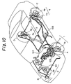
- Fig. 10 is a schematic explanatory view of the prior antilock brake system in the automobile and Fig. 11 is a diagram showing the electrical system of the antilock brake system.
- a conventional antilock brake system comprises rotation detectors 1 to 4, a hydraulic power unit 5, an electronic control section 106 and a relay box 107.
- the rotation detectors 1 to 4 are provided on wheels A to D respectively to detect a rotating condition thereof.
- the rotation detectors 1 to 4 are provided with 1a to 4a and sensor rotors 1b to 4b, respectively.
- the sensors la to 4a are made of, for example, a permanent magnet, a coil, or a pole piece.
- the sensor is attached to a steering knuckle at the front wheel and to a hub spindle at the rear wheel.
- each of the sensor rotors 1b to 4b is provided on the outer periphery with serrations (not shown) formed uniformly along the peripheral direction.
- the sensor rotor is attached to a drive shaft at the front wheel and to a rear hub at the rear wheel.
- sensor rotors 1b to 4b rotate together with the wheels A to D, respectively.
- the sensors 1a to 4a detect the rotating condition of the wheels A to D by sensing the serrations on the outer periphery of the sensor rotors 1b to 4b during their rotations.
- the rotation detectors 1 to 4 transmit detecting signals from the sensors 1a to 4a to an electronic control section 106 to be described hereinafter.
- the hydraulic power unit 105 is provided with four solenoid valves 105a to 105d for corresponding wheels.
- the hydraulic power unit 105 control on-off operations of the solenoid valves 105a to 105d in accordance with control signals from the electronic control section 106, thereby controlling the pressure of a brake fluid supplied to wheel cylinders of the wheels A to D.
- the electronic control section 106 receives the detecting signals from the rotation detectors 1 to 4 and monitors whether or not there is any wheel in a direction to be locked when it is braked in accordance with the detecting signal.
- the electronic control section 106 is made of a printed circuit plate. In the case that there is a wheel in the direction to be locked, the electronic control section 106 control the hydraulic power unit 105 so that the pressure of brake fluid supplied to the wheel cylinder of the corresponding wheel is decreased. In the case that possible locking of the corresponding wheel is avoided, the pressure of brake fluid is increased again.
- a relay box 107 contains motor and fail-safe relays 107a and 107b which amplify the control signal from the electronic control section 106 and applies the amplified control signal to the hydraulic power unit 105.
- 108 is a battery for an automobile as a power source for the antilock brake system, 109 an ignition switch, 110 a stop lamp switch disposed in the vicinity of a brake pedal, 111 a stop lamp constituting a part of a rear lamp, 112 a warning lamp for indicating an abnormal state in the antilock brake system and 113 a diode for lightening the warning lamp 112 when the connector of the electronic control section is in a disengaged position or the fail-safe relay 107b is turned off.
- the hydraulic power unit 105 and relay box 107 are disposed in an engine compartment as shown in Fig. 9.
- the electronic control section 106 is generally disposed in a car interior such as a space under a seat or within front panel.
- the rotation detectors 101 to 104 are provided on the wheel sections as described before.
- the member of electronic control sections is increasing in keeping with an increase in performance while at the same time it is desired to maintain the interior of cars as spacious as possible.
- the electronic control section 106 provided in a car interior requires a long wire harnesses to connect the rotation detectors 1 to 4 in the engine compartment to the section 106.
- EP-A-0 373 551 which forms the pre-characterising portion of Claim 1.
- the solenoid and the motor are connected to the electronic unit through fixed conductor elements.
- solenoid sockets are mounted on a printed circuit plate of said electronic unit disposed in said housing, each of said sockets being associated with and arranged opposite one of said solenoid valves, said solenoid tabs comprising connecting pins passing through a wall of said housing and being inserted into the solenoid sockets by coupling the electronic unit to the hydraulic power unit to apply a voltage to respective coils of the solenoid valves.
- a coil of a solenoid valve in a hydraulic power unit can easily be connected to an electronic control section and/or an electronic element in an electronic unit.
- said electronic unit may be integrally coupled to said hydraulic power unit at a position contacting with a plane exclusive of the plane provided with said coupling ports in said hydraulic power unit, thereby making the shortest distance between said electronic unit and said hydraulic power unit.
- the solenoid socket of the electronic unit is coupled to the coupling portion for the solenoid valve of the hydraulic power unit upon coupling integrally the electronic unit including the electronic control section to the hydraulic power unit. That is, when the electronic power unit including the electronic control section is integrally coupled to the hydraulic power unit, an electrical connection between the coil of the solenoid valve and the electronic control section and/or the electronic element in the electronic unit is automatically effected.
- said motor of said hydraulic power unit has coupling portions for the motor including contact pieces connected to a coil inside the motor.
- Said electric control section is disposed on an electronic unit having coupling portions for receiving another electric elements to be electrically connected to said electronic control section.
- a motor socket is adapted to be coupled to said coupling portions for the motor and including contact pieces to be electrically connected to said motor relay which is mounted on the electronic control section.
- Said electronic unit is integrally secured to said hydraulic power unit.
- Said coupling portions for the motor is coupled to said motor socket.
- the electronic unit is contact with the plane exclusive of the plane provided with the coupling ports in the hydraulic power unit and the electronic element is connected to the electronic control section through the coupling portion of the electronic power unit, it is not necessary to dispose in the car interior parts which constitute the antilock brake system. Accordingly, it is not necessary to provide any wire harness extending between the engine compartment and the car interior in order to interconnect the electronic control section and the hydraulic power unit. Further, it is possible to make the shortest distance between the electronic unit and the hydraulic power unit by integrally coupling the electronic unit to the hydraulic power unit at the position contacting with the plane exclusive of the plane provided with the coupling ports in the hydraulic power unit.
- FIG. 1 to 8 an embodiment of the antilock brake system of the present invention and in particular a hydraulic power unit integrally provided with an electronic unit will be described below.
- the antilock brake system of the present invention shown in Fig. 6 has the same electrical construction and operation as those of the conventional antilock brake system shown in Fig. 10. That is, the antilock brake system of the present invention includes rotation detectors 1 to 4, a hydraulic power unit 5, an electronic unit 6 having an electronic control section 61A, a motor relay 7, a fail-safe relay 8, and a diode 9.
- 21 is a car battery, 22 an ignition switch, 23 a stop lamp switch disposed near a brake pedal, 24 a stop lamp constituting a part of rear lamps, and 25 a warning lamp indicating an abnormal state in the antilock brake system.
- a power source section 10 including the battery 21 through the warning lamp 25 is connected to the electronic unit 6 through power source lines 12.
- the power source lines and earth lines 13 to be connected to earth terminals (not shown) together with signal supplying lines connected to the rotation detectors 1 to 4 described hereinafter constitute a wire harness.
- a connector 15 is coupled to an end of the wire harness.
- the rotation detectors 1 to 4 are the same as the prior rotation detectors 1 to 4 shown in Figs. 9 and 10.
- the rotation detectors 1 to 4 comprises sensors 1a to 4a and sensor rotors 1b to 4b.
- the rotation detectors 1 to 4 detect the rotating conditions of the respective wheels of the automobile and send detecting signals through the signal supplying lines 11 to the electronic control section 61A described hereinafter.
- Figs. 1 and 2 show a hydraulic power unit integrally mounting the electronic unit of the present invention in which the hydraulic power unit 5, the electronic unit 6, the motor relay 7, and the fail-safe relay 8 are integrally assembled in the antilock brake system shown in Fig. 6. This assembly is disposed in the engine compartment in the automobile.
- the hydraulic power unit 5 controls a pressure of brake fluid to a wheel cylinder by controlling an ON-OFF operation of each of four solenoid valves 5a to 5d.
- the ON-OFF operations of the respective solenoid valves 5a to 5d is controlled in accordance with a controlling signal from the electronic control section 61A.
- Means for supplying an electrical power to coils of the respective solenoid valves 5a to 5d will be described hereinafter.
- the hydraulic power unit 5 has a motor 5e which drives a pump (not shown) so as to flow the brake fluid to a master cylinder (not shown).
- the electrical power can be supplied to the motor 5e by connecting a lead line of the motor 5e (described below) to a terminal section 6b of the electronic unit 6.
- a housing 51 of the hydraulic power unit 5 has a housing body 52 and a bottom plate 53.
- the housing body 52 contains the pump, flow control valves or brake fluid flow paths (not shown) adapted to be actuated in connection with ON-OFF operations of the respective solenoid valves 5a to 5d, and the like therein.
- the housing body 52 is provided on a front face with coupling ports 5A to 5D for the brake fluid to the respective cylinders (not shown) and on a side face with coupling ports 5E ad 5F for the brake fluid to the respective brake master cylinders (not shown). Further, the housing body 52 is provided on a rear face with the motor 5e.
- the bottom plate 53 supports the solenoid valves 5a to 5d between the housing body 52 and the plate 53. Connecting pins 5aa to 5da which apply a voltage to the respective coils of the solenoid valves 5a to 5d are secured to the bottom plate 53.
- the connecting pins 5aa to 5da (5aa is shown in Fig. 3 on behalf of them) except top ends thereof are embedded in solenoid tabs 5ab to 5db formed integrally in a resin cover section molding the solenoid valves 5a to 5d.
- the connecting pins 5aa to 5da together with the solenoid tabs 5ab to 5db extend downwardly through the bottom plate 53 in the vicinity of an end portion of the hydraulic power unit 5.
- the electronic unit 6, as shown in Fig. 1, has a printed circuit plate 61 and a housing 62.
- the electronic unit 6 has the same length or less than that of the entire length of the hydraulic power unit 5.
- the printed circuit plate 61 is provided with the electronic control section 61A, terminal sections 61Ba to 61Be, and a wiring section 61C in the antilock brake system shown in Fig. 6.
- the electronic unit section 61A is constructed and operates in the same manner as the electronic unit 106 in the prior antilock brake system. That is, the electronic control section 61A calculates a wheel velocity and wheel acceleration and deceleration and conjecture a car body velocity in accordance with the detecting signals from the respective rotation detectors 1 to 4. If it is decided that there is a wheel in the locking direction upon braking the respective wheels, the electronic control section 61A controls the respective solenoid valves 5a to 5d of the hydraulic power unit 5 so as to reduce the pressure of brake fluid to the wheel cylinder of the corresponding wheel.
- the electronic control unit 61A controls the ON-OFF operations of the solenoid valves 5a to 5d so as to increase the pressure of brake fluid again.
- Terminal sections 61Ba to 61Be are arranged on the printed circuit plate 61, for example, as shown in Fig. 4.
- the terminal section 61Ba connects the signal supplying lines 11, electric power lines 12 and earth lines 13 to the electronic unit 6.
- Each terminal constituting the terminal section 61Ba is a pin which stands on the printed circuit plate 61.
- the terminal correspond to a connector socket 62c in the housing 62, which is described hereinafter.
- the terminal section 61Bb connects a lead line 17 for supplying an electrical power to the motor 5e in the hydraulic power unit 5 to the electronic unit 6.
- the terminal section 61Bb is formed on a printed wiring section on the printed circuit plate 61.
- the terminal section 61Bc connects the solenoid valves 5a to 5d in the hydraulic power unit 5 to the electronic unit 6.
- the terminal section 61Bc is formed on the printed wiring section on the printed circuit plate 61.
- Each of the terminal in the terminal section 61Bc corresponding to the solenoid valves 5a to 5d is associated with a solenoid socket 14 described hereinafter.
- the terminal section 61Bd connects a motor relay 7 described hereinafter to the electronic unit 6.
- Each terminal constituting the terminal section 61Bd is a pin which stands on the printed circuit plate 61.
- the terminal is associated with a socket 62a described later.
- the terminal section 61Be connects a fail-safe relay 8 described later to the electronic unit 6.
- Each terminal constituting the terminal section 61Be is a pin which stands on the printed circuit plate 61.
- the terminal is associated with a socket 62b of the housing 62 described later.
- the wiring section 61C interconnects the electronic control section 61A and terminal sections 61Ba to 61Be.
- the housing 62 is made of aluminum and is coupled to the housing 51 of the hydraulic power unit 5 through attaching brackets 62A and 62B.
- the printed circuit plate 61 is horizontally disposed in the housing 62.
- Sockets 62a and 62b made of resin are embedded in a rear wall of the housing 62 so that they receive the motor relay 7 and fail-safe relay 8.
- the socket 62a is associated with the terminal section 61Bd while the socket 62b is associated with the terminal section 61Be.
- the connector socket 62c is embedded in a side wall of the housing 62 so that the socket 62c receives the connector 15.
- the connector socket 62c is associated with the terminal section 61Ba.
- connecting pin passing-through portions 62d are formed in an upper wall of the housing 62 in opposition to the solenoid tabs 5ab to 5db of the hydraulic power unit 5 so that the tabs 5ab to 5db are inserted into the portion 62d.
- the solenoid sockets 14 are provided between the passing-through portion 62d and the terminal section 61Bc on the printed circuit plate 61 in association with the respective solenoid valves 5a to 5d (only one solenoid socket 14 associated with the solenoid valve 5a is shown in Fig. 3).
- the solenoid socket 14 has a resin body 14a and a connecting terminal 14b secured in the resin body 14a.
- the connecting terminal 14b is soldered to a connecting portion 61Bc on the printed circuit plate 61 at a lower end thereof.
- the respective connecting pins 5aa to 5da can be inserted downwardly into upper portions of the connecting terminals 14b.
- the upper portions are provided with elastic contact pieces (not shown) which contact elastically with the inserted connecting pins 5aa to 5da.
- the motor relay 7 serves to amplify a control signal from the electronic control section 6 so as to switch the motor 5e on or off.
- the motor relay 7 has a terminal 7A, which is electrically connected to the pin terminal constituting the terminal section 61Bd when the motor relay 7 is mounted on the socket 62a in the housing 62.
- the fail-safe relay 8 serves to shut off an electric power to the respective solenoid valves 5a to 5d of the hydraulic power unit 5 in the case that an abnormal state occurs in the antilock brake system.
- the fail-safe relay 8 has the same terminal as the terminal 7A of the motor relay 7. This terminal is electrically connected to the pin terminal constituting the terminal section 61Be when the fail-safe relay 8 is mounted on the socket 62b in the housing 62.
- the diode 9 is connected between lower streams of the warning lamp 25 and the contact of the fail-safe relay 8 so that the diode 9 lights the warning lamp 25 when the fail-safe relay 8 is turned off.
- the diode 9 is connected to a terminal portion (not shown) on the wiring section 61C of the printed circuit plate 61 by means of soldering or the like, so that the diode 9 is disposed between the given terminals of the electronic control section 61A and the terminal section 61Be.
- the electronic unit 6 is coupled to the hydraulic power unit 5 and they are integrally interconnected by the attaching bracket 62A and 62B while the respective tabs 5ab to 5db of the solenoid valves 5a to 5d are inserted into the corresponding solenoid sockets 14.
- the coils of the solenoid valves 5a to 5d are connected to the terminal section 61Bc of the electronic unit 6 when the electronic unit 6 is coupled to the hydraulic power unit 5.
- the assembly of the electronic unit and the hydraulic power unit is disposed at the same position as the hydraulic power unit 105 in the prior antilock brake system shown in Fig. 10.
- the relays 7 and 8 are connected to the terminal sections 61Bd and 61Be of the electronic unit 6 by mounting the relays 7 and 8 on the sockets 62a and 62b in the housing 62 of the electronic unit 6. Accordingly, it is not necessary to interconnect the relays 7 and 8 the hydraulic power unit 5 or relays 7 and 8 and the electronic control section 61A on the printed circuit by the wire harness as carried out in the prior system. This can simplify the process of wire-harnessing.
- the electronic unit 6 since the electronic unit 6 is coupled to the bottom face of the hydraulic power unit 5, on which the coupling ports 5A to 5F are not provided, the electronic unit 6 does not block an arrangement of pipes for brake fluid to the hydraulic power unit 5.
- the electronic control unit 61A and the wiring section 61C are formed on a single sheet of printed circuit plate 61 in the above embodiment, only the electronic control section 61A may be formed on the printed circuit plate and the wiring section 61C may be formed of a wire harness or may be formed into an arrangement in which each bus bar is disposed between a plurality of insulators spaced in a given distance in the assembly of the present invention. In this case, it is possible to form in the wiring section a connecting portion to be connected to a terminal of an electrical element such as the printed circuit plate, the relays 7, 8, the connector 15, or the like by bending an end of the bus bar.
- Fig. 7 shows an assembly of the electronic unit and hydraulic power unit in another antilock brake system.
- parts corresponding to those in Fig. 1 are indicated by dashed signs " ' ".
- coupling ports 5A' to 5F' are provided on an upper face of a hydraulic power unit 5' while an electronic unit 6' is integrally coupled to a front face of the hydraulic power unit 5'.
- the hydraulic power unit 5' and electronic unit 6' are coupled with each other through attaching brackets 62A' and 62B'.
- connecting pins coupled to the coils of the solenoid valves 5a' to 5d' project forward by from the hydraulic power unit 5' in the same manner as the connecting pin 5aa' shown in Fig. 8.
- the connecting pin 5aa' except it's distal end is inserted into or molded in a solenoid tab 5ab'.
- the electronic unit 6' has a printed circuit plate 61' corresponding to the printed circuit plate 61, which is disposed vertically in a housing 62'.
- the electronic unit 6' is provided at a lower portion with a solenoid socket 14' corresponding to the solenoid socket 14.
- the solenoid tab 5ab is inserted into the solenoid socket 14'.
- the connecting pin 5aa' is electrically connected to a terminal section 61Bc' of the printed circuit plate 61' through a connecting terminal 14b' in the solenoid socket 14'.
- solenoid valves 5a' Although only the solenoid valves 5a' is explained, the other solenoid valves 5b' to 5d' have the same construction as the solenoid valve 5a'.
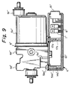
- Fig. 9 shows an assembly of the electronic unit and hydraulic power unit in another antilock brake system.
- ports corresponding to those in Fig. 1 are indicated by double dashed signs " '' ".
- coupling ports 5A'' to 5F'' are provided on an upper or a front face of a hydraulic power unit 5'' while an electronic unit 6'' is integrally coupled to an under face of the hydraulic power unit 5''.
- connecting pins coupled to the coil inside the motor 5e'' protect downward by from the hydraulic power unit 5'' in the same manner as the connecting pin 5aa shown in Fig. 3.
- the electronic unit 6'' has a printed circuit plate 61'' corresponding to the printed circuit plate 61 and also has motor socket 17b'' which mounted on the printed circuit.
- the motor tab 17a'' is inserted into the motor socket 17b''.
- the connecting pin 17a'' is connected to a motor relay 7'' via the printed circuit plate 61''.
- the electronic unit containing the electronic control section since the electronic unit containing the electronic control section is disposed in the engine compartment, it is necessary to dispose member constituting the antilock brake system in the car interior and it is possible to eliminate a limitation which impedes to widen a space in the car compartment even if the antilock brake system is provided in the automobile. It is also possible for the same reason to eliminate a wire harness for the antilock brake system which extends between the engine compartment and the car interior and to simplify a process of wire-harnessing and to enhance a production efficiency.
- the electronic unit does not block the arrangement of pipes for brake fluid to the coupling ports in the hydraulic power unit since the electronic unit is integrally coupled to the hydraulic power unit at the position adjoining the face provided with no coupling port.
Landscapes
- Physics & Mathematics (AREA)
- Engineering & Computer Science (AREA)
- Electromagnetism (AREA)
- Mechanical Engineering (AREA)
- Fluid Mechanics (AREA)
- Transportation (AREA)
- Regulating Braking Force (AREA)
Claims (3)
- Système de freinage antibloquage comportant :un détecteur de rotation (1-4) pour détecter une condition de rotation de chaque roue d'une automobile et pour émettre un signal de détection;une unité de puissance hydraulique (5) comportant des vannes à solénoïde (5a-5d) comportant des pattes de solénoïde (5ab-5dg), ladite unité de puissance hydraulique comportant des orifices d'accouplement pour des tuyaux de fluide de freinage et pour commander la pression du fluide de freinage dans un cylindre de roue de chaque roue en commandant un fonctionnement passant-non passant d'une vanne à solénoïde (5a-5d) au moyen d'un signal de commande électrique;une unité électronique (6) comportant un boîtier (62) et ayant une section de commande électronique (61A) pour produire ledit signal de commande qui commande ladite pression dudit fluide de freinage en réponse audit signal de détection de telle sorte que la roue n'est pas bloquée; etun moteur et des relais de sécurité positive (7, 8) pour fournir de la puissance électrique à ladite unité de puissance hydraulique en réponse audit signal de commande provenant de ladite section de commande électronique;caractérisé en ce que des socles de solénoïde (14) sont montés sur une plaque de circuit imprimé (61) de ladite unité électronique (6) disposée dans ledit boîtier (62), chacun desdits socles étant associé à et agencé en face d'une desdites vannes à solénoïde, lesdites pattes de solénoïde (5ab-5dg) comprenant des chevilles de connexion (5aa-5da) passant à travers une paroi dudit boîtier (62) et étant insérées dans les socles de solénoïde en accouplant l'unité électronique à l'unité de puissance hydraulique pour appliquer une tension à des bobines respectives des vannes à solénoïde (5a-5d).
- Système de freinage antiblocage selon la revendication 1, dans lequel ladite unité électronique (6) est accouplée intégralement à ladite unité de puissance hydraulique (5) à une position de contact avec un plan excepté le plan prévu dans lesdits orifices d'accouplement dans ladite unité de puissance hydraulique en établissant ainsi la distance la plus courte entre ladite unité électronique et ladite unité de puissance hydraulique.
- Système de freinage antiblocage selon la revendication 1, dans lequel un moteur (5e) de ladite unité de puissance hydraulique (5) comporte des portions d'accouplement pour le moteur incluant des pièces de contact reliées à une bobine à l'intérieur du moteur;ladite section de commande électronique (61A) disposée sur l'unité électronique (6) comporte des portions d'accouplement pour recevoir d'autres éléments électroniques à connecter électriquement à ladite section de commande électronique,et un socle de moteur est apte à être accouplé avec lesdites portions d'accouplement pour le moteur et incluant des pièces de contact pour être connectées électriquement audit relais de moteur (7) qui est monté sur la section de commande électronique;ladite unité électronique (6) étant fixée intégralement à ladite unité de puissance hydraulique; lesdites portions d'accouplement pour le moteur étant accouplées audit socle du moteur.
Applications Claiming Priority (4)
| Application Number | Priority Date | Filing Date | Title |
|---|---|---|---|
| JP4356898A JPH06183322A (ja) | 1992-12-21 | 1992-12-21 | アンチロックブレーキシステム |
| JP35689792 | 1992-12-21 | ||
| JP356898/92 | 1992-12-21 | ||
| JP356897/92 | 1992-12-21 |
Publications (3)
| Publication Number | Publication Date |
|---|---|
| EP0604111A2 EP0604111A2 (fr) | 1994-06-29 |
| EP0604111A3 EP0604111A3 (fr) | 1994-11-30 |
| EP0604111B1 true EP0604111B1 (fr) | 1997-03-05 |
Family
ID=26580522
Family Applications (1)
| Application Number | Title | Priority Date | Filing Date |
|---|---|---|---|
| EP93310097A Expired - Lifetime EP0604111B1 (fr) | 1992-12-21 | 1993-12-14 | Système de freinage à anti-blocage |
Country Status (3)
| Country | Link |
|---|---|
| US (1) | US5407260A (fr) |
| EP (1) | EP0604111B1 (fr) |
| DE (1) | DE69308513T2 (fr) |
Families Citing this family (31)
| Publication number | Priority date | Publication date | Assignee | Title |
|---|---|---|---|---|
| EP0592212B1 (fr) * | 1992-10-06 | 1996-12-11 | Sumitomo Wiring Systems, Ltd. | Système de freinage antiblocage |
| US5533905A (en) * | 1993-07-29 | 1996-07-09 | Sumitomo Wiring Systems, Ltd. | Unit integrated system and connector |
| DE4343325A1 (de) * | 1993-12-18 | 1995-06-22 | Telefunken Microelectron | Ventilsteuervorrichtung |
| KR100365535B1 (ko) * | 1994-02-10 | 2003-02-05 | 루카스 인더스트리즈 리미티드 | 차량용블록보호된브레이킹시스템 |
| DE4404273C2 (de) * | 1994-02-10 | 1996-11-28 | Lucas Ind Plc | Hydraulikaggregat für eine blockiergeschützte Fahrzeugbremsanlage |
| DE4412664A1 (de) * | 1994-04-13 | 1995-10-19 | Bosch Gmbh Robert | Elektrohydraulische Druckeinstellvorrichtung, insbesondere für eine schlupfgeregelte Fahrzeugbremsanlage |
| US5452948A (en) * | 1994-10-07 | 1995-09-26 | The Whitaker Corporation | Apparatus and method for electronically controlled hydraulic actuator |
| US5766026A (en) * | 1994-10-07 | 1998-06-16 | The Whitaker Corporation | Electrical connector assembly with sealed and spring biased electrical component |
| DE4443501A1 (de) * | 1994-12-07 | 1996-06-13 | Bosch Gmbh Robert | Elektrisches Gerät |
| US5758931A (en) * | 1995-03-30 | 1998-06-02 | Sumitomo Wiring Systems, Ltd. | Electric control unit integrated with a hydraulic unit in an anti-lock brake system |
| DE19512804C2 (de) * | 1995-04-05 | 2000-06-15 | Lucas Ind Plc | Hydraulikaggregat für eine blockiergeschützte Fahrzeugbremsanlage |
| KR0121814B1 (ko) * | 1995-08-18 | 1997-12-08 | 배순훈 | 2위치/3웨이 솔레노이드 밸브, 이 밸브를 구비한 모듈레이터 및 앤티로크 브레이크 시스템 |
| KR100482791B1 (ko) * | 1996-01-22 | 2005-08-04 | 닛신보세키 가부시키 가이샤 | 브레이크 압력 제어장치 |
| JPH1059152A (ja) * | 1996-08-26 | 1998-03-03 | Nisshinbo Ind Inc | 液圧制御装置 |
| JPH11165627A (ja) * | 1997-12-04 | 1999-06-22 | Sumitomo Electric Ind Ltd | 車両用ブレーキ液圧制御装置 |
| US5992946A (en) * | 1997-12-19 | 1999-11-30 | Itt Manufacturing Enterprises, Inc. | ABS pump connector |
| US6059381A (en) * | 1997-12-19 | 2000-05-09 | Itt Manufacturing Enterprises, Inc. | ABS pump connector |
| DE19959632B4 (de) * | 1998-12-11 | 2009-11-26 | DENSO CORPORATION, Kariya-shi | Hydraulische Steuervorrichtung mit integrierter Motorantriebsschaltung |
| US6241489B1 (en) | 1999-10-08 | 2001-06-05 | Kelsey-Hayes Company | Internal electrical connector for a hydraulic control unit |
| US6375473B1 (en) * | 2000-05-05 | 2002-04-23 | Kelsey-Hayes Company | Electrical interconnection for an electro-hydraulic brake system using wire form buttons |
| DE10061950C2 (de) * | 2000-12-13 | 2002-11-21 | Knorr Bremse Systeme | Elektromechanischer Bremsaktuator |
| US6527348B2 (en) * | 2001-05-22 | 2003-03-04 | Caterpillar Inc | Braking system for a construction machine |
| DE10211798A1 (de) * | 2002-03-16 | 2004-05-19 | Festo Ag & Co. | Kontaktierungseinrichtung für Ventilantriebe und damit ausgestattete Ventilanordnung |
| JP2006027528A (ja) * | 2004-07-20 | 2006-02-02 | Advics:Kk | 車両用ブレーキ液圧制御装置 |
| KR20080025192A (ko) | 2005-07-01 | 2008-03-19 | 다우 글로벌 테크놀로지스 인크. | 저점도 기능성 유체 |
| JP4841884B2 (ja) | 2005-07-19 | 2011-12-21 | 日立オートモティブシステムズ株式会社 | ブレーキユニット |
| DE102010001117A1 (de) * | 2010-01-22 | 2011-07-28 | Robert Bosch GmbH, 70469 | Systemkomponente für ein Kraftfahrzeug, insbesondere Pumpenkomponente, sowie Pumpe |
| EP3144194B1 (fr) * | 2014-05-16 | 2018-05-09 | Robert Bosch GmbH | Unité hydraulique d'abs |
| DE102015220440B4 (de) * | 2014-10-21 | 2023-10-05 | Hl Mando Corporation | Integrierte dynamische Bremsvorrichtung |
| KR20160080899A (ko) * | 2014-12-29 | 2016-07-08 | 주식회사 만도 | 전동식 일체형 브레이크 장치 |
| DE102020205950A1 (de) * | 2020-05-12 | 2021-11-18 | Robert Bosch Gesellschaft mit beschränkter Haftung | Hydraulikblock für ein Hydraulikaggregat einer hydraulischen Fremdkraft-Fahrzeugbremsanlage |
Family Cites Families (13)
| Publication number | Priority date | Publication date | Assignee | Title |
|---|---|---|---|---|
| JPS6013413A (ja) * | 1983-07-05 | 1985-01-23 | 住友電気工業株式会社 | ワイヤリングハ−ネスの相互接続装置 |
| US4697863A (en) * | 1985-10-22 | 1987-10-06 | Amp Incorporated | Electrical connector assembly for antiskid braking system |
| DE3729216A1 (de) * | 1987-09-02 | 1989-03-16 | Teves Gmbh Alfred | Hydraulikaggregat |
| US5127440A (en) * | 1987-12-14 | 1992-07-07 | Alfred Teves Gmbh | Valve block assembly |
| WO1989010286A1 (fr) * | 1988-04-20 | 1989-11-02 | Alfred Teves Gmbh | Dispositif electrohydraulique de regulation de pression |
| GB2225168A (en) * | 1988-10-28 | 1990-05-23 | Akebono Brake Ind | Electromagnetic valve device |
| US5022717A (en) * | 1988-12-12 | 1991-06-11 | Lucas Industries Public Limited Company | Pressure control unit, especially for motor vehicle brake systems |
| DE8910805U1 (de) * | 1989-09-09 | 1991-01-10 | Robert Bosch Gmbh, 7000 Stuttgart | Elektrische Verbindungsvorrichtung |
| DE4001017A1 (de) * | 1990-01-16 | 1991-07-18 | Bosch Gmbh Robert | Montageeinheit aus einem ventilblockaggregat sowie einem steuergeraet |
| EP0520047B1 (fr) * | 1991-01-15 | 1994-10-05 | ITT Automotive Europe GmbH | Regulateur electrohydraulique de pression |
| DE59106681D1 (de) * | 1991-02-20 | 1995-11-16 | Siemens Ag | Ventilsteuergerät. |
| JP2695068B2 (ja) * | 1991-06-20 | 1997-12-24 | 住友電気工業株式会社 | アンチロックブレーキシステム |
| DE4133879A1 (de) * | 1991-10-12 | 1993-04-15 | Bosch Gmbh Robert | Elektrohydraulisches aggregat zur druckregelung in bremsanlagen von fahrzeugen |
-
1993
- 1993-12-14 EP EP93310097A patent/EP0604111B1/fr not_active Expired - Lifetime
- 1993-12-14 DE DE69308513T patent/DE69308513T2/de not_active Expired - Lifetime
- 1993-12-21 US US08/170,901 patent/US5407260A/en not_active Expired - Lifetime
Also Published As
| Publication number | Publication date |
|---|---|
| DE69308513D1 (de) | 1997-04-10 |
| EP0604111A2 (fr) | 1994-06-29 |
| US5407260A (en) | 1995-04-18 |
| EP0604111A3 (fr) | 1994-11-30 |
| DE69308513T2 (de) | 1997-06-12 |
Similar Documents
| Publication | Publication Date | Title |
|---|---|---|
| EP0604111B1 (fr) | Système de freinage à anti-blocage | |
| JP2695068B2 (ja) | アンチロックブレーキシステム | |
| US7433771B2 (en) | Utility vehicle having a plurality of electric devices which are controlled by at least one electronic control device | |
| US6264289B1 (en) | Vehicle braking system | |
| CN102431492B (zh) | 制动踏板的具有停车灯开关功能的位移诊断传感器 | |
| JP2791964B2 (ja) | 路面車両用の電子制動装置 | |
| JP3923093B2 (ja) | 電子ブレーキ装置 | |
| EP0592212B1 (fr) | Système de freinage antiblocage | |
| US5685617A (en) | Unit integrated system and connector | |
| US6203115B1 (en) | Control system for a vehicle braking system | |
| EP0673805B1 (fr) | Assemblage d'unités intégrées pour un système de freinage antiblocage | |
| JP3109295B2 (ja) | ジャンクションブロック一体型電子ユニット | |
| GB2188995A (en) | Hydraulic brake system | |
| JP3063428B2 (ja) | 自動車におけるジャンクションブロック一体型電子ユニット | |
| JP3432561B2 (ja) | アンチロックブレーキシステムにおける電子ユニット一体型油圧ユニット | |
| SE453485B (sv) | Styrblock for modulering av bromstrycket i en bromslasningsskyddsanordning for motorfordon | |
| JP3089884B2 (ja) | アンチロックブレーキシステムにおける電子ユニット一体型油圧ユニット | |
| JPH05139273A (ja) | 液圧ユニツトと電子制御ユニツトの一体化構造 | |
| JPH06115420A (ja) | アンチロックブレーキシステム | |
| JP3232719B2 (ja) | アンチロックブレーキシステム | |
| JPH06183322A (ja) | アンチロックブレーキシステム | |
| KR20220012576A (ko) | 차량의 제동장치 | |
| JP3161134B2 (ja) | プリント回路基板内蔵ユニット | |
| JP3008704B2 (ja) | ジャンクションブロック一体型電子ユニット | |
| KR0109444Y1 (ko) | 에이비에스(abs)경고등 구동장치 |
Legal Events
| Date | Code | Title | Description |
|---|---|---|---|
| PUAI | Public reference made under article 153(3) epc to a published international application that has entered the european phase |
Free format text: ORIGINAL CODE: 0009012 |
|
| 17P | Request for examination filed |
Effective date: 19940214 |
|
| AK | Designated contracting states |
Kind code of ref document: A2 Designated state(s): DE GB |
|
| PUAL | Search report despatched |
Free format text: ORIGINAL CODE: 0009013 |
|
| AK | Designated contracting states |
Kind code of ref document: A3 Designated state(s): DE GB |
|
| 17Q | First examination report despatched |
Effective date: 19950714 |
|
| GRAG | Despatch of communication of intention to grant |
Free format text: ORIGINAL CODE: EPIDOS AGRA |
|
| GRAH | Despatch of communication of intention to grant a patent |
Free format text: ORIGINAL CODE: EPIDOS IGRA |
|
| GRAH | Despatch of communication of intention to grant a patent |
Free format text: ORIGINAL CODE: EPIDOS IGRA |
|
| GRAA | (expected) grant |
Free format text: ORIGINAL CODE: 0009210 |
|
| AK | Designated contracting states |
Kind code of ref document: B1 Designated state(s): DE GB |
|
| REF | Corresponds to: |
Ref document number: 69308513 Country of ref document: DE Date of ref document: 19970410 |
|
| PLBE | No opposition filed within time limit |
Free format text: ORIGINAL CODE: 0009261 |
|
| STAA | Information on the status of an ep patent application or granted ep patent |
Free format text: STATUS: NO OPPOSITION FILED WITHIN TIME LIMIT |
|
| 26N | No opposition filed | ||
| REG | Reference to a national code |
Ref country code: GB Ref legal event code: 746 Effective date: 19980202 |
|
| REG | Reference to a national code |
Ref country code: GB Ref legal event code: IF02 |
|
| PGFP | Annual fee paid to national office [announced via postgrant information from national office to epo] |
Ref country code: DE Payment date: 20121213 Year of fee payment: 20 |
|
| PGFP | Annual fee paid to national office [announced via postgrant information from national office to epo] |
Ref country code: GB Payment date: 20121212 Year of fee payment: 20 |
|
| REG | Reference to a national code |
Ref country code: DE Ref legal event code: R071 Ref document number: 69308513 Country of ref document: DE |
|
| REG | Reference to a national code |
Ref country code: DE Ref legal event code: R071 Ref document number: 69308513 Country of ref document: DE |
|
| REG | Reference to a national code |
Ref country code: GB Ref legal event code: PE20 Expiry date: 20131213 |
|
| PG25 | Lapsed in a contracting state [announced via postgrant information from national office to epo] |
Ref country code: DE Free format text: LAPSE BECAUSE OF EXPIRATION OF PROTECTION Effective date: 20131217 Ref country code: GB Free format text: LAPSE BECAUSE OF EXPIRATION OF PROTECTION Effective date: 20131213 |