EP0603537B1 - Dunstabzugshaube - Google Patents
Dunstabzugshaube Download PDFInfo
- Publication number
- EP0603537B1 EP0603537B1 EP93118455A EP93118455A EP0603537B1 EP 0603537 B1 EP0603537 B1 EP 0603537B1 EP 93118455 A EP93118455 A EP 93118455A EP 93118455 A EP93118455 A EP 93118455A EP 0603537 B1 EP0603537 B1 EP 0603537B1
- Authority
- EP
- European Patent Office
- Prior art keywords
- filter
- extractor hood
- grease filter
- grease
- air
- Prior art date
- Legal status (The legal status is an assumption and is not a legal conclusion. Google has not performed a legal analysis and makes no representation as to the accuracy of the status listed.)
- Expired - Lifetime
Links
Images
Classifications
-
- F—MECHANICAL ENGINEERING; LIGHTING; HEATING; WEAPONS; BLASTING
- F24—HEATING; RANGES; VENTILATING
- F24C—DOMESTIC STOVES OR RANGES ; DETAILS OF DOMESTIC STOVES OR RANGES, OF GENERAL APPLICATION
- F24C15/00—Details
- F24C15/20—Removing cooking fumes
- F24C15/2035—Arrangement or mounting of filters
-
- F—MECHANICAL ENGINEERING; LIGHTING; HEATING; WEAPONS; BLASTING
- F24—HEATING; RANGES; VENTILATING
- F24C—DOMESTIC STOVES OR RANGES ; DETAILS OF DOMESTIC STOVES OR RANGES, OF GENERAL APPLICATION
- F24C15/00—Details
- F24C15/20—Removing cooking fumes
- F24C15/2078—Removing cooking fumes movable
- F24C15/2092—Removing cooking fumes movable extendable or pivotable
Definitions
- the present invention relates to an extractor hood with a grease filter and a suction system for applying this grease filter with a substantially uniform vacuum in order to convey gases to be cleaned, in particular air contaminated by cooking fumes, through this grease filter, and with a suction area in front of the grease filter, which can be changed by air guiding devices such as in flaps, drawer-like pull-outs and the like (see, for example, DE-C-4 040 717).
- the receiving area of the extractor hood for the cooking vapors at least covers the area of the hob so that as many of the rising cooking vapors as possible are detected by the extractor hood.
- extractor hoods and food are functionally extremely advantageous, but they appear to be too voluminous in smaller kitchens and have a rather disruptive effect on the operation of the hob.
- extractor hoods are Realized which are smaller in structure and which are additionally equipped with air guiding devices, such as plates, drawer-like pull-outs and the like, in order to enlarge the collecting area of the extractor hood.
- An extractor hood with a grease filter and a suction system for supplying this grease filter with negative pressure in order to suck in kitchen fumes to be cleaned in particular, which does the job, is characterized according to the invention in that the air guiding devices are equipped with filter elements facing the origin of the gases to be cleaned, which are opposite the real one Grease filter is characterized by a higher permeability and a significantly reduced absorption behavior, and that the area of these filter elements facing away from the inflowing gases flows into the suction areas of the actual grease filter.
- An extractor hood equipped according to these features according to the invention is characterized in that the actual fat filter connected directly or indirectly upstream of the suction fan is finally used and responsible for the absorption of the fat particles and other contaminants of the air occurring during cooking and roasting.
- This can be inserted into the housing in an essentially air flow-tight manner, so that there is no fear of incorrect air in the intake and exhaust air ducts.
- the additional air-guiding devices take into account the areas that are not directly covered by the actual grease filter, but are also to be detected, and specifically by means of filter elements which, due to their design, oppose the inflowing, cleaned gases, a very low flow resistance, and accordingly also have a low absorption capacity for the contaminants , but are able to pick up and hold easily settling particles from the gas.
- the arrangement of the invention equips the gas flow of the area covered as a whole to the main grease filter, where it undergoes the essential and final cleaning.
- the extractor hood according to the invention is characterized in that the value of the flow resistance of the filter elements per unit area is less than half the value of the flow resistance of the actual one Grease filter is.
- the actual main grease filter can consist of six layers, while the air guiding devices are equipped with filter elements made of two layers.
- the air guiding device is preferably implemented by a drawer-like pull-out which, in the idle state, is inserted essentially below the actual main grease filter and which, in the functional position, is pulled out toward the operator, with a narrower area remaining as an overlap with the actual main grease filter.
- the air flow channel formed between the filter element and the upper pull-out part thus ends in the suction area of the main grease filter itself and does not need to be particularly sealed, but only guided through a guide skirt, since in this area no significant flow resistance is opposed by the filter elements, which could give rise to disturbing leakage currents .
- the extractor hood according to the invention is characterized in that input elements for controlling functions of the extractor hood are arranged within the flow space between one of the filter elements and the actual main grease filter.
- input elements can also be sensors which detect the presence of gases to be cleaned and, as a function thereof, automatically control the operation of the extractor hood.
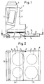
- An extractor hood as shown in the figures, is suitable for typical use above hobs in kitchens. Such hobs are usually essentially square and have four hobs. 2, a projection of the position of these hotplates (15) on the underside of the extractor hood is indicated by dashed lines. An appropriately widened extractor hood can be used for wider cooktops.
- an electric motor-operated fan 3 which draws air from the space 4 and thus generates negative pressure there and blows this air out via an outlet connection 5.
- the room 4 is closed by a so-called fat filter 6, through which contaminated air, particularly during roasting and cooking processes, passes as a result of the negative pressure prevailing in the room 4, the grease and other contamination particles largely be absorbed in this grease filter 6.
- the space 4 is formed in such a closed manner and the grease filter 6 is in inserted a recording that as far as possible no air is sucked in except through the grease filter.
- a carbon filter 7 can be used within the room 4, which is able to absorb odors.
- a drawer-like pull-out 8 is arranged in the housing of the extractor hood and can be pulled out to the front. In the figures, this is shown in the pulled-out position.
- This drawer-like pull-out has fixed walls on the front, top and on the side walls.
- a filter element 9 is inserted on the underside. The turns of the drawer-like pull-out and the filter element 9 form a flat channel which, when the drawer-like pull-out 8 is pulled out, ends openly in the front region of the grease filter 6.
- An apron 11 closes this channel 10 towards the filter 6.
- the grease filter 6 In order to achieve the highest possible cleaning effect for the contaminated air that is brought in, the grease filter 6 must be designed as densely and homogeneously as possible, as a result of which it not only offers a high absorption capacity, but also opposes the air with a relatively high flow resistance.
- the fan must be correspondingly powerful in order to generate the necessary, under pressure in the room 4 to overcome this grease filter 6 by the air to be cleaned. In front of the filter 6 this is not available under pressure and so a filter element is used in the present extractor hood in the drawer-like pull-out 8 brought, which, in order to be flowed through, is designed very permeable. This means that the absorption capacity of this filter element 9 is also relatively low, which is not only accepted with approval, but is also desirable.
- the actual cleaning of the contaminated air, which is passed through the filter element 9, takes place in exactly the same way as the cleaning of the air that is otherwise sucked in in the main grease filter 6. It is therefore not necessary to guide the drawer-like pull-out 8 and its apron 11 with regard to Specially design tightness against false currents.
- a substantial negative pressure within the channel 10 is not built up anyway due to the lack of considerable flow resistance in the area of the filter element 9.
- the actual main filter 6 can, for example, have eight to twelve layers in expanded metal, whereas the filter element 9 has only two to four layers of expanded metal. As a result, there is less overlap of the individual spaces between the expanded metal layers and the permeability is so low that the air flowing through can pass through almost unhindered without a significant drop in pressure.
- Presetting input elements or sensor elements 12 can be arranged within the channel 10, that is to say above the filter element 9, which detect the rising smoke from the hotplates and evaluate it to control the extractor hood.
Landscapes
- Engineering & Computer Science (AREA)
- Chemical & Material Sciences (AREA)
- Combustion & Propulsion (AREA)
- Mechanical Engineering (AREA)
- General Engineering & Computer Science (AREA)
- Ventilation (AREA)
- Filtering Materials (AREA)
- Filtering Of Dispersed Particles In Gases (AREA)
Applications Claiming Priority (2)
| Application Number | Priority Date | Filing Date | Title |
|---|---|---|---|
| DE4243944A DE4243944A1 (de) | 1992-12-23 | 1992-12-23 | Dunstabzugshaube |
| DE4243944 | 1992-12-23 |
Publications (2)
| Publication Number | Publication Date |
|---|---|
| EP0603537A1 EP0603537A1 (de) | 1994-06-29 |
| EP0603537B1 true EP0603537B1 (de) | 1997-01-22 |
Family
ID=6476450
Family Applications (1)
| Application Number | Title | Priority Date | Filing Date |
|---|---|---|---|
| EP93118455A Expired - Lifetime EP0603537B1 (de) | 1992-12-23 | 1993-11-15 | Dunstabzugshaube |
Country Status (3)
| Country | Link |
|---|---|
| EP (1) | EP0603537B1 (es) |
| DE (2) | DE4243944A1 (es) |
| ES (1) | ES2099350T3 (es) |
Families Citing this family (13)
| Publication number | Priority date | Publication date | Assignee | Title |
|---|---|---|---|---|
| DE19505683A1 (de) * | 1995-02-20 | 1996-08-22 | Bosch Siemens Hausgeraete | Dunstabzugshaube |
| DE19825324B4 (de) * | 1998-06-05 | 2013-04-18 | BSH Bosch und Siemens Hausgeräte GmbH | Hausgerät mit einem Ausfahrkörper |
| DE19906318B4 (de) * | 1999-02-16 | 2004-02-12 | Imperial-Werke Ohg | Dunstabzugshaube |
| DE10015745A1 (de) * | 2000-03-29 | 2001-10-11 | Bsh Bosch Siemens Hausgeraete | Dunstabzugsvorrichtung |
| DE10016295A1 (de) * | 2000-03-31 | 2001-10-04 | Bsh Bosch Siemens Hausgeraete | Dunstabzugshaube |
| DE20316130U1 (de) | 2003-10-21 | 2004-04-15 | BSH Bosch und Siemens Hausgeräte GmbH | Satz von Schubladen-Dunstabzugshauben |
| DE102005002148A1 (de) * | 2005-01-17 | 2006-07-20 | BSH Bosch und Siemens Hausgeräte GmbH | Küchendunstabzugsvorrichtung |
| DE102005008373A1 (de) * | 2005-02-23 | 2006-08-31 | BSH Bosch und Siemens Hausgeräte GmbH | Dunstabzugshaube |
| DE202011110424U1 (de) | 2011-11-04 | 2014-01-23 | Elica S.P.A | Abzugshaube zum Filtern gasförmiger Stoffe aus häuslicher Umgebung mit ausziehbarer Schublade |
| CN109114608B (zh) * | 2017-06-26 | 2020-11-10 | 博西华电器(江苏)有限公司 | 用于油烟机的控制方法及油烟机 |
| US11285421B2 (en) | 2018-04-12 | 2022-03-29 | Electrolux Home Products, Inc. | Filter media for filtration of cooking fumes |
| CN110207222A (zh) * | 2018-10-30 | 2019-09-06 | 华帝股份有限公司 | 集烟箱及应用其的集成灶 |
| CN112815368A (zh) * | 2021-01-15 | 2021-05-18 | 山东佳士博食品有限公司 | 一种带有油烟处理的油炸食品加工装置 |
Family Cites Families (2)
| Publication number | Priority date | Publication date | Assignee | Title |
|---|---|---|---|---|
| US3496704A (en) * | 1966-12-07 | 1970-02-24 | Broan Mfg Co Inc | Convertible hood for console range |
| DE4040717C1 (es) * | 1990-12-19 | 1992-04-02 | Bosch-Siemens Hausgeraete Gmbh, 8000 Muenchen, De |
-
1992
- 1992-12-23 DE DE4243944A patent/DE4243944A1/de not_active Withdrawn
-
1993
- 1993-11-15 EP EP93118455A patent/EP0603537B1/de not_active Expired - Lifetime
- 1993-11-15 ES ES93118455T patent/ES2099350T3/es not_active Expired - Lifetime
- 1993-11-15 DE DE59305247T patent/DE59305247D1/de not_active Expired - Lifetime
Also Published As
| Publication number | Publication date |
|---|---|
| DE59305247D1 (de) | 1997-03-06 |
| DE4243944A1 (de) | 1994-06-30 |
| EP0603537A1 (de) | 1994-06-29 |
| ES2099350T3 (es) | 1997-05-16 |
Similar Documents
| Publication | Publication Date | Title |
|---|---|---|
| EP0603537B1 (de) | Dunstabzugshaube | |
| EP1481201B1 (de) | ABZUGSHAUBE UND VERFAHREN ZUR ABSAUGUNG UND/ODER AUFREINIGUNG KONTAMINIERTER TRäGERSTOFFE | |
| EP2570735B1 (de) | Dunstabzugssystem und Verfahren zum Betreiben eines Dunstabzugssystems | |
| EP2397775A2 (de) | Abzugsvorrichtung | |
| EP3473937B1 (de) | System und verfahren zum absaugen und filteren von kochdünsten | |
| DE4201209C2 (de) | Dunstabzugsvorrichtung zur Anordnung über dem Kochfeld eines Küchenherdes | |
| DE2705395A1 (de) | Lueftungseinrichtung fuer kochgeraete, insbesondere fuer herde | |
| DE202006016179U1 (de) | Lufterfassungseinrichtung, insbesondere Wrasenerfassungseinrichtung | |
| DE102019116237A1 (de) | Filtereinrichtung zum Filtern von Wrasen für eine Absaugeinrichtung, Absaugeinrichtung sowie Verfahren und Vorrichtung zum Betreiben einer Absaugeinrichtung | |
| EP2210048A2 (de) | Dunstabzugsvorrichtung | |
| DE3718686A1 (de) | Dunstabzugshaube, insbesondere fuer kuechen | |
| EP3598006B1 (de) | Dunstabzugsvorrichtung für ein in ein möbel einbaubares kochfeld, verfahren zum betreiben der dunstabzugsvorrichtung und möbel mit kochfeld und mit dunstabzugsvorrichtung | |
| WO2009101099A1 (de) | Dunstabzugssystem mit separatem filtergehäuse | |
| EP0050277A2 (de) | Luftreinigungsgerät, insbesondere über Küchenherden o.dgl. anzubringende Dunstabzugshaube | |
| EP3485199B1 (de) | Lüftungsanordnung mit einer dunstabzugshaube | |
| DE102017112329A1 (de) | Dunstabzugshaube | |
| DE19950817A1 (de) | Dunstabzugsvorrichtung | |
| EP3653940B1 (de) | Dunstabzugshaube | |
| EP0603538B1 (de) | Dunstabzugshaube | |
| EP0603539B1 (de) | Dunstabzugshaube mit einer akustischen Sensorstrecke | |
| DE102020124068A1 (de) | Downdraftlüfter und Verfahren zum Betreiben | |
| EP2252834A2 (de) | Dunstabzugsvorrichtung und verfahren zur reinigung von küchenluft | |
| DE102018119698A1 (de) | Dunstabzugssystem für Kochfelder | |
| DE3144777A1 (de) | Verfahren zum absaugen und filtern von ueber einer kochstelle einer kueche entstehendem wrasen und anreicherung der kuechenluft mit frischluft und vorrichtung zur durchfuehrung des verfahrens | |
| EP3299727A1 (de) | Abdeckvorrichtung für einen muldenlüfter und muldenlüftereinlasseinheit mit einer abdeckvorrichtung |
Legal Events
| Date | Code | Title | Description |
|---|---|---|---|
| PUAI | Public reference made under article 153(3) epc to a published international application that has entered the european phase |
Free format text: ORIGINAL CODE: 0009012 |
|
| AK | Designated contracting states |
Kind code of ref document: A1 Designated state(s): DE ES IT SE |
|
| 17P | Request for examination filed |
Effective date: 19941209 |
|
| GRAG | Despatch of communication of intention to grant |
Free format text: ORIGINAL CODE: EPIDOS AGRA |
|
| 17Q | First examination report despatched |
Effective date: 19960215 |
|
| GRAH | Despatch of communication of intention to grant a patent |
Free format text: ORIGINAL CODE: EPIDOS IGRA |
|
| GRAH | Despatch of communication of intention to grant a patent |
Free format text: ORIGINAL CODE: EPIDOS IGRA |
|
| GRAA | (expected) grant |
Free format text: ORIGINAL CODE: 0009210 |
|
| AK | Designated contracting states |
Kind code of ref document: B1 Designated state(s): DE ES IT SE |
|
| REF | Corresponds to: |
Ref document number: 59305247 Country of ref document: DE Date of ref document: 19970306 |
|
| ITF | It: translation for a ep patent filed |
Owner name: 0508;07MIFSTUDIO JAUMANN |
|
| REG | Reference to a national code |
Ref country code: ES Ref legal event code: FG2A Ref document number: 2099350 Country of ref document: ES Kind code of ref document: T3 |
|
| PLBE | No opposition filed within time limit |
Free format text: ORIGINAL CODE: 0009261 |
|
| STAA | Information on the status of an ep patent application or granted ep patent |
Free format text: STATUS: NO OPPOSITION FILED WITHIN TIME LIMIT |
|
| 26N | No opposition filed | ||
| PGFP | Annual fee paid to national office [announced via postgrant information from national office to epo] |
Ref country code: SE Payment date: 20071126 Year of fee payment: 15 |
|
| EUG | Se: european patent has lapsed | ||
| PG25 | Lapsed in a contracting state [announced via postgrant information from national office to epo] |
Ref country code: SE Free format text: LAPSE BECAUSE OF NON-PAYMENT OF DUE FEES Effective date: 20081116 |
|
| PGFP | Annual fee paid to national office [announced via postgrant information from national office to epo] |
Ref country code: DE Payment date: 20121130 Year of fee payment: 20 |
|
| PGFP | Annual fee paid to national office [announced via postgrant information from national office to epo] |
Ref country code: ES Payment date: 20121122 Year of fee payment: 20 Ref country code: IT Payment date: 20121124 Year of fee payment: 20 |
|
| REG | Reference to a national code |
Ref country code: DE Ref legal event code: R071 Ref document number: 59305247 Country of ref document: DE |
|
| PG25 | Lapsed in a contracting state [announced via postgrant information from national office to epo] |
Ref country code: DE Free format text: LAPSE BECAUSE OF EXPIRATION OF PROTECTION Effective date: 20131116 |
|
| REG | Reference to a national code |
Ref country code: ES Ref legal event code: FD2A Effective date: 20140925 |
|
| PG25 | Lapsed in a contracting state [announced via postgrant information from national office to epo] |
Ref country code: ES Free format text: LAPSE BECAUSE OF EXPIRATION OF PROTECTION Effective date: 20131116 |