EP0602469B1 - Verfahren und Vorrichtung zur Schrägspurmagnetbandaufzeichnung - Google Patents
Verfahren und Vorrichtung zur Schrägspurmagnetbandaufzeichnung Download PDFInfo
- Publication number
- EP0602469B1 EP0602469B1 EP93119477A EP93119477A EP0602469B1 EP 0602469 B1 EP0602469 B1 EP 0602469B1 EP 93119477 A EP93119477 A EP 93119477A EP 93119477 A EP93119477 A EP 93119477A EP 0602469 B1 EP0602469 B1 EP 0602469B1
- Authority
- EP
- European Patent Office
- Prior art keywords
- time code
- code information
- information item
- component
- temporal resolution
- Prior art date
- Legal status (The legal status is an assumption and is not a legal conclusion. Google has not performed a legal analysis and makes no representation as to the accuracy of the status listed.)
- Expired - Lifetime
Links
Images


Classifications
-
- G—PHYSICS
- G11—INFORMATION STORAGE
- G11B—INFORMATION STORAGE BASED ON RELATIVE MOVEMENT BETWEEN RECORD CARRIER AND TRANSDUCER
- G11B5/00—Recording by magnetisation or demagnetisation of a record carrier; Reproducing by magnetic means; Record carriers therefor
- G11B5/008—Recording on, or reproducing or erasing from, magnetic tapes, sheets, e.g. cards, or wires
- G11B5/00813—Recording on, or reproducing or erasing from, magnetic tapes, sheets, e.g. cards, or wires magnetic tapes
- G11B5/00847—Recording on, or reproducing or erasing from, magnetic tapes, sheets, e.g. cards, or wires magnetic tapes on transverse tracks
- G11B5/0086—Recording on, or reproducing or erasing from, magnetic tapes, sheets, e.g. cards, or wires magnetic tapes on transverse tracks using cyclically driven heads providing segmented tracks
-
- G—PHYSICS
- G11—INFORMATION STORAGE
- G11B—INFORMATION STORAGE BASED ON RELATIVE MOVEMENT BETWEEN RECORD CARRIER AND TRANSDUCER
- G11B15/00—Driving, starting or stopping record carriers of filamentary or web form; Driving both such record carriers and heads; Guiding such record carriers or containers therefor; Control thereof; Control of operating function
- G11B15/18—Driving; Starting; Stopping; Arrangements for control or regulation thereof
- G11B15/1808—Driving of both record carrier and head
- G11B15/1875—Driving of both record carrier and head adaptations for special effects or editing
-
- G—PHYSICS
- G11—INFORMATION STORAGE
- G11B—INFORMATION STORAGE BASED ON RELATIVE MOVEMENT BETWEEN RECORD CARRIER AND TRANSDUCER
- G11B27/00—Editing; Indexing; Addressing; Timing or synchronising; Monitoring; Measuring tape travel
- G11B27/10—Indexing; Addressing; Timing or synchronising; Measuring tape travel
- G11B27/19—Indexing; Addressing; Timing or synchronising; Measuring tape travel by using information detectable on the record carrier
- G11B27/28—Indexing; Addressing; Timing or synchronising; Measuring tape travel by using information detectable on the record carrier by using information signals recorded by the same method as the main recording
- G11B27/32—Indexing; Addressing; Timing or synchronising; Measuring tape travel by using information detectable on the record carrier by using information signals recorded by the same method as the main recording on separate auxiliary tracks of the same or an auxiliary record carrier
- G11B27/322—Indexing; Addressing; Timing or synchronising; Measuring tape travel by using information detectable on the record carrier by using information signals recorded by the same method as the main recording on separate auxiliary tracks of the same or an auxiliary record carrier used signal is digitally coded
- G11B27/323—Time code signal, e.g. on a cue track as SMPTE- or EBU-time code
Definitions
- the invention relates to a method and an apparatus for Helical track magnetic tape recording.
- VHS recorders for synchronization a control signal at 40 ms intervals (in 50 Hz systems) in a longitudinal track on the lower band edge to record. The occurrence of these signals can be counted and as Time information can be evaluated.
- the disadvantage here is that the cassette must always be transported to the beginning of the tape, to be able to determine an absolute value.
- Control Track Longitudinal CTL system was also introduced in 1986 introduced for VHS.
- temporal variation of the previous unused trailing edge of the servo synchronous signal can all 40 ms an information bit can be transmitted.
- the disadvantage of this is the resolution of 2 s and the relative coding of the frame pulses.
- time code according to IEC 461 proven. With high resolution (500 ⁇ s / bit in longitudinal time Code LTC) are in the longitudinal as well as in the helical track Time information nested.
- the disadvantage here is that high resolution. It prevents at high belt transport speeds reading out the absolute value.
- the invention is based on the object of a digital recording method and a corresponding recording device for video and audio signals to be specified with a Time coding system of high resolution, that at high Tape transport speeds (search / forward or reverse) the Can read lower resolution timestamps, however, especially can be realized inexpensively.
- This task is accomplished by solved the invention specified in claims 1 and 7.
- Advantageous developments of the invention are in the dependent claims specified.
- the trailing edge modulation in the phase reference pulses on the synchronous track because of them large resolution requirements and the resulting high Frequency is not possible.
- the recording method according to the invention Comes with an additional one Longitudinal track.
- the one to be recorded Time code information is broken down into two parts.
- a share contains the relevant values such as hours / minutes / seconds (h / m / s). This portion is in a longitudinal track with a bit spacing recorded even at high tape speeds can be read.
- the second part contains the frame count information and will into the signal of the longitudinal track Frequency separation nested (solution 2).
- solution 1 is disclosed for explanatory purposes only and is not part of the invention.
- the signal of track 1 (also named S1) contains every 40 ms bit information.
- Each frame signal identifies an in closed area, the recorded in the helical tracks Data. It gets the servo system from the video signal processing fed, has a duration of 40 ms and is used for Synchronization.
- a section of 25 frame pulses thus comprises only the time of one second.
- the recorded signal of the The first three frame pulses is a symmetrical rectangular sequence a pulse-pause ratio of exactly 50%. It is used for Synchronization.
- the following data bits are marked with a Pulse / pause ratio of 25% in the case of an H bit and 75% in the Case marked with an L bit.
- the evaluation includes count levels, that increment during the high state of the input signal and decrement during the L state. With everyone On the positive edge, the meter reading is saved, the meter then deleted again. The counter value becomes 0, positive or tested negative.
- the respective decision provides a synchronous bit, H bit, L bit.
- the synchronization bits are followed by 3 control bits, which are necessary for the Ge entire system display tax information. For example: number the tracks / frame (depending on network frequency 50/60 Hz), the Aspect ratio (16: 9 or 4: 3) and whether HD (high definition) or SD (standard definition) signals during recording were used.
- control bits could be assigned as follows 011 ⁇ Longplay, HD, 16: 9, 50Hz
- the following 19 bits carry the information in groups Hours (4 bits), minutes (6 bits) and seconds (6 bits), each binary counted and each with a parity bit (even parity) protected per group.
- the described sequence of 25 bits recorded once every second.
- the signal of track 2 (also called S2) includes for everyone Frame impulse a pattern. For each of the 25 frame pulses shown there is a 6 bit pattern that is in sync with everyone Frame information from S1 starts, but before the frame intervals expire ends. This pattern contains the 5 bits Count information for the frame number, the sixth bit is used for Parity check. The logical states are due to the pulse-pause ratios of the individual bits. It is 33 % in the case of an H bit and 66% in the case of an L bit. The Values 25%, 50%, 75% for S1 signals and 33%, 66% for S2 signals have been chosen to handle all signals with a single To be able to generate clock.
- Track 1 The information from track 1 is used for synchronization (Counter status assignment) of both tracks and carries the time counter value low resolution (h / m / s). It is therefore always necessary.
- Track 2 carries a dependent, high-resolution time information, the temporal events take place synchronously with change in track 1.
- a high-frequency signal is preferably used for the fine resolution (Frame numbers) and a low frequency for normal resolution (h / m / s) successively recorded in one track.
- the previously described S1 is used as the base signal (low frequency) Signal used, the falling edge of each recorded in S1 Pulses with a sequence of 6 bits shifted in time becomes.
- one is symmetrical in front of and behind the flank symmetrical sequence of 3 bits each added or added. It each of these bits consists of one or two oscillation trains, with a pulse-pause ratio of 50%. This is ensures that the amplitude reduction for positive and negative pulses of a bit is constant, which is a Evaluation made easier.
- the bit length for H bits and L bits is equal.
- the maximum bit length results due to the permissible shift of the low-frequency time code signal.
- a value of +/- 3 ms also becomes a in rewind mode enable clean identification.
- the high-frequency is not interleaved Time codes during this phase to identify the start of the data sequence definitely make sure.
- the frame counter continues counting normally, the trailing edges of the preamble pulses however not modulated in time. With the first control bit becomes the nesting of the high-resolution time code information then continued.
- Solutions 1 and 2 represent a cost-optimal solution to the time code problem
- the tape needs to be moved as quickly as possible to be able to read and display the entire time information.
- the system then returns to the start of the frame when inserting the cassette was recognized first.
- solution 1 In rewinding mode, solution 1 focuses entirely on fine resolution waived, and the data from S1 are evaluated.
- the solution 2 includes the shutdown automatically, because at a higher tape feed speed the nested higher frequencies Parts of the entire playback system are dampened so much, that no more digital time signal can be obtained from them can.
- the groups are separated in time because the Time code information is recorded sequentially.
- Fig. 1 shows the signal of the recorded track S1.
- the signal track S1 contains bit information every 40 ms.
- Every frame signal F denotes a self-contained area, the data recorded in the helical tracks.
- the sequence shown of 25 frame pulses F thus comprises the time of 1 second.
- the recorded signal Sy of the first three frame pulses F is a symmetrical rectangular sequence with a pulse-pause ratio of exactly 50%. It is used for synchronization.
- the synchronization bits are followed by 3 control bits C, which are used for the Show overall system tax information.
- the following 19 bits carry the information in groups Hours h (4 bits), minutes m (6 bits) and seconds s (6 bits), each binary counted and each with a parity bit P (even Parity) per group.
- the sequence described from 25 Bits are recorded once every second.
- the subsequent data bits of the frame pulses F4 to F25 are by a pulse / pause ratio of 25% in the case of an H bit and 75% in the case of an L bit.
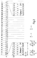
- Fig. 2 shows the recorded track S2 of solution 1.
- This pattern has in the first 5 bits the count information f4 to f0 for the frame number F1, the sixth bit is used for parity checking.
- a pattern has a length b and a bit the length a.
- a ratio of lengths from b to a is 6.
- the length of the display pulse whether high H or low L is specified with c and the aspect ratio from a to c equal to 3 is measured.
- Track S1 is equal to the track recorded in solution 1 S1.
- Track S1 is a low frequency signal
- track S2 is a high frequency signal.
- the low frequency serving as the base signal Signal of track S1 is used in such a way that symmetrically in front and behind on every falling flank of track S1 the edge is a symmetrical sequence of three bits each is added or added.
- the added bits are there one or two oscillation trains with a pulse-pause ratio of 50%. This ensures that in rewinding the amplitude reconstruction for positive and negative Sequence of a bit is constant, which facilitates evaluation.
- the bit length for H bits and L bits is the same here, so that the length of the evaluation window is constant for all bits.
- the maximum bit length results from the permissible shift of the low-frequency time code signal. A value of +/- 3 ms will also enable clean identification in rewinding.
- Fig. 4 shows the basic circuit for recording and regeneration of the signals.
- the left side represents the generation of the signals.
- a microcontroller ⁇ C provides S1 for the tracks and S2 the logic states at out1 and out2 together with one timed clock OCR.
- Out1 and out2 are in a subsequent D flip-flop synchronized with the clock and are at Q1 as S1 or at Q2 as S2 for recording.
- On the The reproduction part is shown on the right half of FIG.
- the rectangular signals in 1 are at the outputs of the amplifiers as well as in2.
- a multiplexer m follows, which is one of these signals at the high-resolution measurement input Microcontrollers ⁇ C according to the given scheme using the signal ctrl switches.
- This configuration shown is in use to use a microcontroller ⁇ C, the few High-resolution measurement inputs ICR, with which the time between input signal edges with an accuracy of 250 ns lets measure, but which via a variety of normal inputs disposes. However, if two of these ICR inputs are available, the lines in1 and in2 are directly connected to ICR1 or Connect ICR2. The multiplexer m with the control line ctrl can then be omitted. A multiplexing process in the form of a signal Selection in the microcontroller is still possible.
- the assignment of the signals S1, S2 and ctrl is via a Period of 48 ms shown.
- the hatched areas set the switch points with their right and left boundaries for H bits or L bits. Both signals are with each other coupled.
- the next signal change, in 5 labeled event2 or event3 is used by the microcontroller registered and implemented as described in the diagram field.
- the entries (event2, 3 and event4, 5 and following) represent possible signal change points, but it becomes dependent of logical state, only either event 2 or event 3 give.
Description
- Fig. 1
- die aufgezeichnete Spur S1 der Lösung 1,
- Fig. 2
- die aufgezeichnete Spur S2 der Lösung 1,
- Fig. 3
- die aufgezeichneten Spuren S1 und S2 der Lösung 2,
- Fig. 4
- die prinzipielle Schaltung zur Aufzeichnung und Regenerierung der Signale und
- Fig. 5
- die Zuordnung der Signale S1, S2.
Claims (7)
- Verfahren zur Schrägspurmagnetbandaufzeichnung für analoge und/oder digitale Signale unter Verwendung mindestens eines zusätzlichen Längsspurkopfes, zugehörigen Aufnahme-/Wiedergabeverstärkern sowie einer Zeitzähleinrichtung, wobei eine Zeitcodeinformation digital auf einer Längsspur (S1) aufgezeichnet wird, wobei die Zeitcodeinformation in zwei Anteile (h,m,s;framenr) eingeteilt wird, von denen der eine Anteil (h,m,s) eine Zeitcodeinformation mit geringerer Zeitauflösung angibt und der andere Anteil (framenr) eine Zeitcodeinformation mit höherer zeitlicher Auflösung angibt, wobei Frameimpulse (F) in der Längsspur (S1) aufgezeichnet werden, dadurch gekennzeichnet, daß die Vorderflanken der Frameimpulse (F) jeweils zur Synchronisation benutzt werden und die Rückflanken des jeweiligen Frameimpulses entsprechend des eingestellten Puls/Pausenverhältnisses H- oder L-Bits des Anteils (h,m,s) der Zeitcodeinformation mit geringerer Zeitauflösung kennzeichnen und daß der Anteil (framenr) der Zeitcodeinformation mit höherer Zeitauflösung frequenzmäßig versetzt von dem Anteil der Zeitcodeinformation mit geringerer Zeitauflösung auf derselben Längsspur (S1) digital aufgezeichnet wird.
- Verfahren nach Anspruch 1, wobei, der Anteil (framenr) der Zeitcodeinformation mit höherer Zeitauflösung zeitlich miteinander verkoppelt mit dem Anteil (framenr) der Zeitcodeinformation mit geringerer Zeitauflösung auf derselben Längsspur (S2) aufgezeichnet wird.
- Verfahren nach Anspruch 1 oder 2, wobei, eine Zählstufe während des H-Zustandes des Frameimpulses (F) inkrementiert, während des L-Zustandes dekrementiert, bei jeder positiven Flanke der Zählerstand abgespeichert und der Zähler gelöscht wird.
- Verfahren nach einem der vorhergehenden Ansprüche, wobei, zur Einstellung des Puls-/Pausen-Verhältnisses die Werte 25%,50%,75% für das Signal der Frameimpulse (F) selbst gewählt werden, wobei die Prozentwerte die Länge eines H-Zustandes in Bezug auf die Gesamtdauer der Signale angeben und daß die entsprechenden Signale aus einem Takt erzeugt werden.
- Verfahren nach einem der vorhergehenden Ansprüche, wobei ein hochfrequentes Signal für die Feinauflösung und ein niederfrequentes Signal für die Normalauflösung aufgezeichnet wird.
- Verfahren nach einem der vorhergehenden Ansprüche, wobei, symmetrisch vor und hinter einer Rückflanke des Frameimpulses (F) eine symmetrische Folge von jeweils 3 Bit ein- bzw. hinzugefügt wird, wobei jedes dieser Bits aus Signalen mit einem Puls-/Pausenverhältnis, daß durch den Wert 50% gekennzeichnet ist, besteht, wobei der Prozentwert die Länge eines H-Zustandes in Bezug auf die Gesamtdauer des Signales angibt.
- Vorrichtung zur Schrägspurmagnetbandaufzeichnung für analoge und/oder digitale Signale mit mindestens einem zusätzlichen Längsspurkopf, zugehörigen Aufnahme/Wiedergabeverstärkern sowie einer Zeitzähleinrichtung, wobei die Vorrichtung eine Zeitcodeinformation digital auf einer Längsspur (S1) aufzeichnet, wobei eine Einteilung der Zeitcodeinformation in zwei Anteile (h,m,s;framenr) erfolgt, von denen der eine Anteil (h,m,s) eine Zeitcodeinformation mit geringerer Zeitauflösung angibt und der andere Anteil (framenr) eine Zeitcodeinformation mit höherer zeitlicher Auflösung angibt, wobei eine Aufzeichnung von Frameimpulsen (F) in der Längsspur (S1) erfolgt, dadurch gekennzeichnet, daß eine Synchronisation basierend auf den Vorderflanken der Frameimpulse (F) erfolgt und die Rückflanken des jeweiligen Frameimpulses entsprechend des eingestellten Puls/Pausenverhältnisses H- oder L-Bits des Anteils (h,m,s) der Zeitcodeinformation mit geringerer Zeitauflösung kennzeichnen und wobei die Aufzeichnung des Anteils (framenr) der Zeitcodeinformation mit höherer Zeitauflösung frequenzmäßig versetzt von dem Anteil (h,m,s) der Zeitcodeinformation mit geringerer Zeitauflösung auf derselben Längsspur (S1) erfolgt.
Applications Claiming Priority (2)
| Application Number | Priority Date | Filing Date | Title |
|---|---|---|---|
| DE4241986A DE4241986A1 (de) | 1992-12-12 | 1992-12-12 | Verfahren zur Schrägspurmagnetbandaufzeichnung |
| DE4241986 | 1992-12-12 |
Publications (3)
| Publication Number | Publication Date |
|---|---|
| EP0602469A2 EP0602469A2 (de) | 1994-06-22 |
| EP0602469A3 EP0602469A3 (de) | 1995-11-29 |
| EP0602469B1 true EP0602469B1 (de) | 2000-04-12 |
Family
ID=6475115
Family Applications (1)
| Application Number | Title | Priority Date | Filing Date |
|---|---|---|---|
| EP93119477A Expired - Lifetime EP0602469B1 (de) | 1992-12-12 | 1993-12-03 | Verfahren und Vorrichtung zur Schrägspurmagnetbandaufzeichnung |
Country Status (7)
| Country | Link |
|---|---|
| US (1) | US5644675A (de) |
| EP (1) | EP0602469B1 (de) |
| JP (1) | JP3490484B2 (de) |
| KR (1) | KR100280574B1 (de) |
| CN (1) | CN1039948C (de) |
| DE (2) | DE4241986A1 (de) |
| ES (1) | ES2145759T3 (de) |
Families Citing this family (4)
| Publication number | Priority date | Publication date | Assignee | Title |
|---|---|---|---|---|
| JPH1066036A (ja) * | 1996-08-15 | 1998-03-06 | Oki Electric Ind Co Ltd | Tv方式変換装置 |
| JPH10290420A (ja) | 1997-04-15 | 1998-10-27 | Matsushita Electric Ind Co Ltd | 記録再生装置 |
| CN100349224C (zh) * | 1999-01-07 | 2007-11-14 | 日本胜利株式会社 | 数据记录方法及装置 |
| JP2001118366A (ja) * | 1999-10-20 | 2001-04-27 | Brother Ind Ltd | 不連続位置検出装置及び検出方法 |
Citations (1)
| Publication number | Priority date | Publication date | Assignee | Title |
|---|---|---|---|---|
| US4703311A (en) * | 1986-06-09 | 1987-10-27 | Gse Electronic Systems, Inc. | Method and apparatus for transferring an information code onto the synchronization track of a video tape and a video tape produced according to said method |
Family Cites Families (13)
| Publication number | Priority date | Publication date | Assignee | Title |
|---|---|---|---|---|
| US3681524A (en) * | 1970-06-16 | 1972-08-01 | Columbia Broadcasting Syst Inc | Multiple frequency time code generator and reader |
| GB1577133A (en) * | 1976-03-19 | 1980-10-22 | Rca Corp | Video information record and playback apparatus |
| US4665431A (en) * | 1982-06-24 | 1987-05-12 | Cooper J Carl | Apparatus and method for receiving audio signals transmitted as part of a television video signal |
| US4516164A (en) * | 1982-10-21 | 1985-05-07 | Stypher Corporation | Apparatus for decoding video address code signals |
| GB2131996A (en) * | 1982-11-30 | 1984-06-27 | George Saint | Data storage devices |
| DE3309029C2 (de) * | 1983-03-14 | 1985-05-15 | Winfried Dipl.-Ing.(FH) 8000 München Walter | Verfahren zum Bestimmen der momentanen Bandlänge eines Videomagnetbandes und nach diesem Verfahren bespielte Videomagnetbänder |
| US4663678A (en) * | 1984-06-18 | 1987-05-05 | Odetics, Inc. | System for writing and reading digital data interspersed with analog audio frequency data on magnetic recording tape |
| JPH0795390B2 (ja) * | 1985-08-07 | 1995-10-11 | 株式会社日立製作所 | 磁気記録再生装置の制御信号記録装置 |
| JPH0664777B2 (ja) * | 1986-10-03 | 1994-08-22 | シンワ株式会社 | テ−プレコ−ダのテ−プ巻終り検出装置 |
| DE3742469C1 (de) * | 1987-12-15 | 1989-05-24 | Graetz Nokia Gmbh | Videorecorder mit einer Einrichtung zur Aufzeichnung einer zusaetzlichen Steuersignalspur auf ein Videoband |
| CN1049978A (zh) * | 1989-05-03 | 1991-03-20 | 何吉松 | 太空棋 |
| NL9000635A (nl) * | 1990-03-20 | 1991-10-16 | Philips Nv | Digitaal opteken- en weergavesysteem. |
| JP2741112B2 (ja) * | 1991-03-29 | 1998-04-15 | シャープ株式会社 | ディジタル変調方式およびディジタル変調装置 |
-
1992
- 1992-12-12 DE DE4241986A patent/DE4241986A1/de not_active Withdrawn
-
1993
- 1993-12-03 DE DE59310007T patent/DE59310007D1/de not_active Expired - Fee Related
- 1993-12-03 ES ES93119477T patent/ES2145759T3/es not_active Expired - Lifetime
- 1993-12-03 EP EP93119477A patent/EP0602469B1/de not_active Expired - Lifetime
- 1993-12-09 KR KR1019930026951A patent/KR100280574B1/ko not_active IP Right Cessation
- 1993-12-11 CN CN93120820A patent/CN1039948C/zh not_active Expired - Fee Related
- 1993-12-13 JP JP31195093A patent/JP3490484B2/ja not_active Expired - Fee Related
-
1995
- 1995-03-27 US US08/410,417 patent/US5644675A/en not_active Expired - Fee Related
Patent Citations (1)
| Publication number | Priority date | Publication date | Assignee | Title |
|---|---|---|---|---|
| US4703311A (en) * | 1986-06-09 | 1987-10-27 | Gse Electronic Systems, Inc. | Method and apparatus for transferring an information code onto the synchronization track of a video tape and a video tape produced according to said method |
Also Published As
| Publication number | Publication date |
|---|---|
| US5644675A (en) | 1997-07-01 |
| EP0602469A3 (de) | 1995-11-29 |
| EP0602469A2 (de) | 1994-06-22 |
| KR940015974A (ko) | 1994-07-22 |
| CN1089050A (zh) | 1994-07-06 |
| JPH06259944A (ja) | 1994-09-16 |
| DE59310007D1 (de) | 2000-05-18 |
| JP3490484B2 (ja) | 2004-01-26 |
| KR100280574B1 (ko) | 2001-03-02 |
| DE4241986A1 (de) | 1994-06-16 |
| ES2145759T3 (es) | 2000-07-16 |
| CN1039948C (zh) | 1998-09-23 |
Similar Documents
| Publication | Publication Date | Title |
|---|---|---|
| DE3018602C2 (de) | ||
| DE3420169C2 (de) | ||
| DE3137906C2 (de) | ||
| DE3825960C2 (de) | ||
| DE3809179C2 (de) | Verfahren und Vorrichtung zur Aufnahme und Wiedergabe eines digitalen Signals unter Verwendung eines Rotationskopfs | |
| DE2427225C3 (de) | Schaltungsanordnung zur Demodulation digitaler Information | |
| CH619314A5 (de) | ||
| DE2841728A1 (de) | Verfahren und schaltungsanordnung zur wiedergabe eines auf magnetband gespeicherten videosignals mit veraenderlicher geschwindigkeit | |
| DE3004799C2 (de) | ||
| AT389787B (de) | Zeitzaehltaktgenerator | |
| DE2924695C2 (de) | ||
| DE3236311A1 (de) | Datensynchronisierer | |
| EP0602469B1 (de) | Verfahren und Vorrichtung zur Schrägspurmagnetbandaufzeichnung | |
| DE4444783C2 (de) | Verfahren zur Aufzeichnung/Wiedergabe von Gray-kodierten Datensignalen und Dekodierschaltkreis für ein Festplattenlaufwerk | |
| DE2912754C2 (de) | ||
| EP0198841B1 (de) | Spurnachgesteuertes magnetbandgerat mit querspuraufzeichnung | |
| DE3615468C2 (de) | ||
| DE2916074C2 (de) | ||
| DE2938246C2 (de) | Schaltungsanordnung zum Feststellen des Anfangspunktes von Datenpaketen aus digitalen Signalen und Synchronisierungssignalen | |
| DE3225406C2 (de) | ||
| DE4343809C2 (de) | Schrägspurmagnetbandaufzeichnungsgerät für digitale Signale mit verschiedenen Betriebsarten | |
| EP0533789B1 (de) | Recorder für digitale signale | |
| EP0578078B1 (de) | Verfahren zur Spurfolgesteuerung in einem Recorder | |
| DE2654070C3 (de) | Anordnung zum Einschreiben in einen und Auslesen aus einem Pufferspeicher | |
| DE2850953C2 (de) | Schaltungsanordnung für ein PCM-Aufzeichnungs und -Wiedergabegerät |
Legal Events
| Date | Code | Title | Description |
|---|---|---|---|
| PUAI | Public reference made under article 153(3) epc to a published international application that has entered the european phase |
Free format text: ORIGINAL CODE: 0009012 |
|
| AK | Designated contracting states |
Kind code of ref document: A2 Designated state(s): DE ES FR GB IT |
|
| PUAL | Search report despatched |
Free format text: ORIGINAL CODE: 0009013 |
|
| AK | Designated contracting states |
Kind code of ref document: A3 Designated state(s): DE ES FR GB IT |
|
| 17P | Request for examination filed |
Effective date: 19960530 |
|
| 17Q | First examination report despatched |
Effective date: 19961203 |
|
| GRAG | Despatch of communication of intention to grant |
Free format text: ORIGINAL CODE: EPIDOS AGRA |
|
| RTI1 | Title (correction) |
Free format text: METHOD AND APPARATUS FOR RECORDING ON A MAGNETIC TAPE WITH SLANT TRACKS |
|
| GRAG | Despatch of communication of intention to grant |
Free format text: ORIGINAL CODE: EPIDOS AGRA |
|
| GRAG | Despatch of communication of intention to grant |
Free format text: ORIGINAL CODE: EPIDOS AGRA |
|
| GRAH | Despatch of communication of intention to grant a patent |
Free format text: ORIGINAL CODE: EPIDOS IGRA |
|
| GRAH | Despatch of communication of intention to grant a patent |
Free format text: ORIGINAL CODE: EPIDOS IGRA |
|
| GRAA | (expected) grant |
Free format text: ORIGINAL CODE: 0009210 |
|
| ITF | It: translation for a ep patent filed |
Owner name: JACOBACCI & PERANI S.P.A. |
|
| AK | Designated contracting states |
Kind code of ref document: B1 Designated state(s): DE ES FR GB IT |
|
| GBT | Gb: translation of ep patent filed (gb section 77(6)(a)/1977) |
Effective date: 20000413 |
|
| REF | Corresponds to: |
Ref document number: 59310007 Country of ref document: DE Date of ref document: 20000518 |
|
| ET | Fr: translation filed | ||
| REG | Reference to a national code |
Ref country code: ES Ref legal event code: FG2A Ref document number: 2145759 Country of ref document: ES Kind code of ref document: T3 |
|
| PLBE | No opposition filed within time limit |
Free format text: ORIGINAL CODE: 0009261 |
|
| STAA | Information on the status of an ep patent application or granted ep patent |
Free format text: STATUS: NO OPPOSITION FILED WITHIN TIME LIMIT |
|
| 26N | No opposition filed | ||
| REG | Reference to a national code |
Ref country code: GB Ref legal event code: IF02 |
|
| PGFP | Annual fee paid to national office [announced via postgrant information from national office to epo] |
Ref country code: GB Payment date: 20051110 Year of fee payment: 13 |
|
| PGFP | Annual fee paid to national office [announced via postgrant information from national office to epo] |
Ref country code: DE Payment date: 20051216 Year of fee payment: 13 |
|
| PGFP | Annual fee paid to national office [announced via postgrant information from national office to epo] |
Ref country code: FR Payment date: 20051222 Year of fee payment: 13 |
|
| PGFP | Annual fee paid to national office [announced via postgrant information from national office to epo] |
Ref country code: ES Payment date: 20051227 Year of fee payment: 13 |
|
| PGFP | Annual fee paid to national office [announced via postgrant information from national office to epo] |
Ref country code: IT Payment date: 20061231 Year of fee payment: 14 |
|
| PG25 | Lapsed in a contracting state [announced via postgrant information from national office to epo] |
Ref country code: DE Free format text: LAPSE BECAUSE OF NON-PAYMENT OF DUE FEES Effective date: 20070703 |
|
| GBPC | Gb: european patent ceased through non-payment of renewal fee |
Effective date: 20061203 |
|
| REG | Reference to a national code |
Ref country code: FR Ref legal event code: ST Effective date: 20070831 |
|
| PG25 | Lapsed in a contracting state [announced via postgrant information from national office to epo] |
Ref country code: GB Free format text: LAPSE BECAUSE OF NON-PAYMENT OF DUE FEES Effective date: 20061203 |
|
| REG | Reference to a national code |
Ref country code: ES Ref legal event code: FD2A Effective date: 20061204 |
|
| PG25 | Lapsed in a contracting state [announced via postgrant information from national office to epo] |
Ref country code: FR Free format text: LAPSE BECAUSE OF NON-PAYMENT OF DUE FEES Effective date: 20070102 Ref country code: ES Free format text: LAPSE BECAUSE OF NON-PAYMENT OF DUE FEES Effective date: 20061204 |
|
| PG25 | Lapsed in a contracting state [announced via postgrant information from national office to epo] |
Ref country code: IT Free format text: LAPSE BECAUSE OF NON-PAYMENT OF DUE FEES Effective date: 20071203 |