EP0601445B1 - Oberflächenentwässerungseinrichtung - Google Patents
Oberflächenentwässerungseinrichtung Download PDFInfo
- Publication number
- EP0601445B1 EP0601445B1 EP93119296A EP93119296A EP0601445B1 EP 0601445 B1 EP0601445 B1 EP 0601445B1 EP 93119296 A EP93119296 A EP 93119296A EP 93119296 A EP93119296 A EP 93119296A EP 0601445 B1 EP0601445 B1 EP 0601445B1
- Authority
- EP
- European Patent Office
- Prior art keywords
- cover
- water drainage
- latch
- drainage apparatus
- fixation
- Prior art date
- Legal status (The legal status is an assumption and is not a legal conclusion. Google has not performed a legal analysis and makes no representation as to the accuracy of the status listed.)
- Expired - Lifetime
Links
Images


Classifications
-
- E—FIXED CONSTRUCTIONS
- E03—WATER SUPPLY; SEWERAGE
- E03F—SEWERS; CESSPOOLS
- E03F3/00—Sewer pipe-line systems
- E03F3/04—Pipes or fittings specially adapted to sewers
- E03F3/046—Open sewage channels
-
- E—FIXED CONSTRUCTIONS
- E02—HYDRAULIC ENGINEERING; FOUNDATIONS; SOIL SHIFTING
- E02D—FOUNDATIONS; EXCAVATIONS; EMBANKMENTS; UNDERGROUND OR UNDERWATER STRUCTURES
- E02D29/00—Independent underground or underwater structures; Retaining walls
- E02D29/12—Manhole shafts; Other inspection or access chambers; Accessories therefor
- E02D29/14—Covers for manholes or the like; Frames for covers
- E02D29/1427—Locking devices
-
- E—FIXED CONSTRUCTIONS
- E03—WATER SUPPLY; SEWERAGE
- E03F—SEWERS; CESSPOOLS
- E03F5/00—Sewerage structures
- E03F5/04—Gullies inlets, road sinks, floor drains with or without odour seals or sediment traps
- E03F5/06—Gully gratings
-
- E—FIXED CONSTRUCTIONS
- E03—WATER SUPPLY; SEWERAGE
- E03F—SEWERS; CESSPOOLS
- E03F5/00—Sewerage structures
- E03F5/04—Gullies inlets, road sinks, floor drains with or without odour seals or sediment traps
- E03F5/06—Gully gratings
- E03F2005/065—Gully gratings with elastic locking elements
Definitions
- the invention relates to a surface drainage device according to the preamble of claim 1.
- the invention is a drainage channel, which one is built into the floor Channel body a cover or a grate put on and with the gutter is connected.
- fasteners can now be used in different ways Be trained. If the surface drainage facilities must meet particularly high requirements, so are generally used as bolts used in threaded holes (as fastening counterparts) are screwed in, which are attached to the frames are. The manufacture of such an arrangement is relative expensive because the threads are cut on the finished channel Need to become.
- DE-U-88 02 530 also discloses a drainage channel a floor and two parallel side walls having channel body, in which on the bearing surfaces Side walls provided a releasably fixed cover is, with a molded part made of plastic in each side wall is embedded, an insertion groove open to the gutter and receiving chambers for a crossbar Receiving chambers of both side walls are aligned opposite, the cross bar with its ends in the engages both receiving chambers.
- the cross bar is with a threaded hole for a fastening screw equipped with its shaft through a hole the cover extends and with her head on the cover supports.
- the invention has for its object a surface drainage device of the type mentioned at the beginning simple way to train that the total cost can be lowered.
- An essential idea of the invention is that the body does not finished "counterparts, but only receptacles are provided, in which different counterparts can be installed. In this way, a Variety "of gutter bodies, which significantly reduces the manufacturing and storage costs.
- the manufacture of the fastening counterparts, which are easier to handle in any case than the complete gutter bodies, is simple. The storage costs are low even with a very large number of different fastening counterparts.
- the receiving devices are designed such that the fastening counterparts are removable after installation. This makes retrofitting very easy.
- a plurality of receiving devices is preferably seen before and forms them in such a way that either fastening counterparts or damping elements for damping a vertical movement between cover and body can be used are.
- damping elements are known per se. This can further reduce costs, because for damping elements, that are only needed in special cases, none special training of the channel or its frames necessary is.
- the mounting counterparts can be made with threaded holes equip so that screws can be used as fasteners are. This will create a screw connection much simplified. In particular, you do not have to thread cut the frame of an otherwise finished gutter.
- one on the body attached clamp spring and as attachments one at the Cover attached peg with a thickened when in use include leading front end formed in such a way are that the spigot in one to the plane in which the cover extends in a substantially vertical direction in a receiving opening of the clamping spring or its elastic Deformation can be used and is held during insertion.
- Such a snap fit ensures adequate attachment, where the assembly, i.e. the placement of the cover on the gutter is very simple.
- the thickened section is preferably at the front end conical and at its end facing the cover frustoconical. This makes them ready for assembly forces required to lower the cover.
- the receiving opening of the clamping spring is preferably elongated educated. This allows the pin on any Places used along the longitudinal axis of the receiving opening be so that the manufacturing tolerances of gutter and cover can be relatively high.
- the clamping spring can be attached with play such that the pin, when inserted into the receiving opening, the clamping spring can move. This also serves large tolerances allow in the manufacture of gutter and cover.
- the embodiment already indicated above is preferably in which the receiving opening is elongated is used and at the same time the clamping spring Play in only one direction, namely perpendicular to the longitudinal axis the receiving opening attached so that it from the pin at Insert in the receiving opening in the to the longitudinal axis of the Recording opening can be moved in the vertical direction.
- the two degrees of freedom are therefore different Way ensured what a very stable structure with it brings.
- the clamping spring is in the essentially band-shaped and has a lower, essentially U- or V-shaped spring section and two adjacent U-shaped holding sections, each with one leg end in one leg of the spring section pass over and their open sides protrude outwards.
- the Clamp spring is then in a (preferably) rectangular Opening of a flat part arranged so that it with the legs of the holding sections two opposite one another Reaches over the edges of the opening of the flat part.
- the detachable one is generally sufficient Clamping seat, in which the force when assembling is greater than the force when lifting the cover.
- the pin is rotatable about its longitudinal axis (in the cover) and its thickened end has two mutually opposite spreading surfaces, so that the pin for a parallel position of the spreading surfaces Spreads the clamping spring along the longitudinal axis of the receiving opening and removable from the receiving opening and into the receiving opening can be used.
- a flat piece serves as the attachment point for the clamping spring, that can be inserted into a side open pocket in the frame is. It is also advantageous if the cover is a Holding nose, which then the flat piece against slipping out backs out of your pocket when the cover is on the gutter or body sits.
- the receiving devices can be used part. Much more can also use the traverse mentioned at the beginning (possibly also additionally) can be used.
- fastening device for screwless Fastening one that is characterized by that the fasteners at least one bolt, the stored in the cover and towards a longitudinal edge the cover in a locking position and out of this in an open position is displaceable, and that the fastening counterparts include a body counterpart that when moving the bolt in the locking position engages with the latch that the cover on the body is held.
- a bar is relatively simple manufacture and captively connect to the cover.
- the cover is preferably a cast grate.
- the bolt preferably has latching devices which e.g. can be designed as a detent spring and with the cover are in elastic engagement.
- the locking device arrives engages with a counter-catch in the cover in such a way that the bolt in the locked position (preferably also in the open position) with the bolt piece in this position is fixed. This is an unintentional one Unable to open or remove the cover.
- the latch is preferably in one of the recesses in the Cover attached, which as inflow openings for to be discharged Serve water. As a result, no additional occurs Weakening of the cover.
- the bolt preferably has an opening, which in the locking position together with the recess, in which the bolt is attached, forms an overall opening, which is essentially that of the other recesses corresponds in the cover.
- an opening which in the locking position together with the recess, in which the bolt is attached, forms an overall opening, which is essentially that of the other recesses corresponds in the cover.
- the recess in which the latch is attached is preferably as a slot open to the longitudinal edge of the cover educated. This allows the bolt to enter the opening from the outside be inserted.
- the latch preferably includes a cover portion which is in the locking position the slot in its open Area closed up to the longitudinal edge. This is ensures that the surface of the cover is even runs without depressions and therefore no dirt accumulates can.
- the surface of the bar is preferably over that the cover sunk so far that when driving over the Cover the latch remains unloaded. This is usually sufficient Fractions of millimeters. This ensures that the guides in which the bolt can be moved, permanently stay common.
- the bolt is preferably in a direction of displacement vertical plane essentially double T-shaped or as Dovetail guide trained.
- the recess in the Cover is designed accordingly, so it has rails which are gripped by the bolt.
- the latch is preferably on the longitudinal edge of the cover end facing away from a clearing device, the when opening and moving from the locked position Cleans dirt from the transfer track. This is a easy opening possible even after long use.
- the clearing facilities are simple to design if they have sloping surfaces for lifting dirt when moving include. So the dirt is not compacted, but actually cleared.
- the locking counterpart comprises a nose, which in a holding recess of the cover in the area of the latch protrudes, the bolt a holding portion reaching under the nose having.
- a nose is very easy with the Pour the frame together on this.
- the holding recess in the cover is shaped to correspond to the nose, that moving the cover in the direction of its longitudinal edges, thus in the longitudinal direction of a drainage channel prevented becomes.
- the fastening device for fastening the Cover on the drainage channel thus forms at the same time a safeguard against the cover moving the gutter.
- the bolts and the bolt counterparts and, if applicable, the hooking elements and hooking openings are preferably symmetrical in this way arranged on the body and on the cover that the Longitudinal edges of the cover are interchangeable. This will make it It is easier to put the cover on the body.
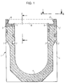
- a drainage channel is shown in cross section, which has a channel body 1 with upwardly projecting side walls 2, 2 'and a bottom 5 and reinforcing ribs 4.
- On the upper edges 3, 3 'of the channel 1 are frames 10, 10 'in the material (polymer concrete) of the rest of the gutter body poured.
- the frames 10, 10 ' have supports 6, 6' for Place a cover 30 on (in Fig. 1 with openwork Lines indicated).
- the Pockets 11, 11 'and 12 are designed so that fastening counterparts 20 can be used. These are below described in more detail.
- hooking elements 13 are provided on the frames 10, 10 ′, which in corresponding recesses of the cover 30 can be used so that on the cover 30 to the outside projecting holding pieces 29 lie under the hooking elements 13 and so the cover 30 against the corresponding edge Secure lifting upwards. This will be further below explained in more detail.
- the damping elements 50 are made in a manner known per se formed of an elastic plastic and dimensioned so that they have a sufficient amount above the requirements 6, 6 'protrude so that when the cover is in place 30 somewhat compressed.
- lugs 26 are provided on the frames 10, 10 ', which can cooperate with bars 60, which in one Cover 30 can be arranged. The way it works described in more detail below.
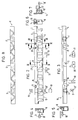
- FIGS 2-4 and 7 are mounting counterparts 20 'and 20 '' shown, which have threaded holes 21, so that a cover 30 by means of screws (as fastening pieces) can secure on the gutter.
- a mounting counterpart 20 which has a rectangular opening 25. This is for recording a clamping spring described in more detail below.
- the pockets 11, 11 'and 12 are on the inside (in Fig. 3 to above) is slightly tapered. To this It is possible to design appropriately sized fasteners 20 drive in with light hammer blows that they sit securely in pockets 11, 11 'or 12. Means a screwdriver, the fasteners 20 nevertheless get them out of pockets 11, 11 'or 12.
- a fastening device based on the Figures 9-18 explained in more detail, either that in the figures 2 and 3 shown mounting piece 20 (with a rectangular opening 25) or can be used directly in the frames. At direct insertion into the frame 10, 10 'becomes the opening above the central pocket 12 corresponding to the opening 25 educated.
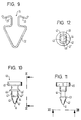
- the clamping spring shown in Fig. 9 has a lower one Spring section 22, which is substantially V-shaped is. Of course, it can also be U-shaped or Execute semicircular.
- clamping spring At the upper end of the clamping spring are holding sections 23, 23 ' provided which has a substantially U-shaped cross section have and each with one leg in one leg of the lower spring section 22.
- the holding sections 23, 23 ' point outwards with their openings and form between them an elongated receiving opening 24.
- This clamping spring can be made of a band-shaped metal strip or be made of plastic.
- This clamping spring is now either in a mounting counterpart 20 (Fig. 2) or directly into the frame 10, 10 '(as in 13-18 shown) used.
- Fig. 2 This clamping spring is now either in a mounting counterpart 20 (Fig. 2) or directly into the frame 10, 10 '(as in 13-18 shown) used.
- Fig. 13 This clamping spring is now either in a mounting counterpart 20 (Fig. 2) or directly into the frame 10, 10 '(as in 13-18 shown) used.
- the clamping spring in Fig. 13 after can be moved left and right so that the edges the opening 25 more or less deep in the holding sections 23, 23 'intervene.
- a pin 40 as a fastening piece attached, which, as shown in Fig. 11, has a tip 41, which sits at the end of a conical surface 42.
- the cone surface 42 goes into an oppositely inclined holding surface 43 above, the angle of the holding surface 43 is steeper than that Angle of the conical surface 42.
- the holding surface 43 in turn goes at its tapered end into a shaft 44, at the End of a head 45 sits.
- a receiving opening 29 (FIGS. 13, 14) is provided, through which a fastening piece 40 according to FIGS. 10-12 can be inserted into the opening 24, until it with its widened head 45 on a support surface 19 of the receiving opening 29 rests.
- This position is in Fig. 15 shown.
- the holding sections 23, 23 ' such on the steeply shaped support surface 43 that a Pulling the fastening piece 40 out of the clamping spring 20 is practically not possible.
- the fastening piece 40 can have a symmetrical shape, then the holding surface 43 is formed such that lifting the cover 30 with appropriate effort is possible.
- the attachment piece 40 such as shown in Figures 10-12, no axisymmetric shape on. Rather, it has two spreading surfaces 47, 47 ', which have essentially the same diameter as the conical surface 42 at its thick end. These spreading surfaces 47, 47 'lie directly opposite each other. At a 90 ° angle to this are the Holding surfaces 43 and the shaft 44 are molded so that the in The configuration shown in Figures 10-12 arises.
- the fastening piece has retaining lugs 46, 46 ', which at the rotational position of the fastener shown in Fig. 17 40 this in the receiving opening 29 by engagement under the bearing surfaces 19, 19 'against falling out to back up.
- FIG Fastening devices Another preferred embodiment of FIG Fastening devices with reference to Figures 19-27 closer explained.
- the cover 30 Openings 31, 31 ', which are separated by ribs 37 are separated.
- the longitudinal edges 32, 32 'of the cover 30 have the hooking openings mentioned at the beginning on a longitudinal edge 32 ' 39 only in the surface of the cover 30 are sunk in, so that the holding pieces under the hook openings 29 lie.
- the cover 30 At the other longitudinal edge 32 is the cover 30 with openings 39 'which pass through the entire cover 30, so that no holding pieces 29 on the other longitudinal edge 32 lie.
- two are from each other spaced recesses 31 in the cover 30 carried out via a slot 33 to the longitudinal edge 32.
- This slot 33 has on its edge 32 facing End a holding recess 38 which is shaped so that the nose 26 formed on the groove is essentially form-fitting fits in. This is a shift in Cover 30 effectively prevented in the longitudinal direction of the channel.
- the nose 26 has, as shown in Fig. 20, over and under free space.
- the slot 33 or the associated opening 31 is with guide rails 36, 36 'provided inwardly in the slot 33 or the opening 31 protrude.
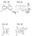
- a latch 60 which has a double-T-shaped cross section has, as shown in Figures 21 and 25 is.
- the latch 60 comprises an upper cover plate 64 and a base plate 65, which with the cover plate 64 over an intermediate piece 66 of smaller width (in the longitudinal direction of the channel) connected is.
- the intermediate piece 66 At its end facing the longitudinal edge 32 is the intermediate piece 66 so far on the base plate 65 and the cover plate 64 reset that a holding section 71 is formed, who can reach under the nose 26.
- the cover plate 64 is pulled as far out towards the longitudinal edge 32, that when the latch 60 is in its closed position (according to FIG. 19) with the longitudinal edge 32 essentially flush.
- the cover plate 64 At its end facing away from the longitudinal edge 32 is the cover plate 64 provided with inclined surfaces 67 so that when moving the Riegel 60 (in Fig. 19 to the right) dirt that on the Rails 36, 36 'lies, can be lifted off.
- a detent spring serves as well as in its open position 61, which the intermediate piece 66 with a holding portion 62nd (Fig. 27). At its end, the detent spring 61 is with outwardly bent latching sections 63, which then, when the latch 60 is in its locked position, snap into notches 68.
- the bolt 60 is also provided with an opening 69, so that its ends (between the inclined surfaces 67) fork-shaped are designed.
- the opening 69 is designed in such a way that from opening 69 and the remainder of the opening 31 with slot 33 composed opening area of a corresponds to those in which the other recesses 31 in of the cover 30. This is clearly evident in Fig. 19 see.
- the height of the surface 70 of the cover plate 64 is slightly less than that of the cover 30, so that no force on the bolt when driving over the cover 30 60 or its surface 70 acts. They are also on the cover 30 over its surface 34 excellent Knobs 35 provided, on the one hand, the slip resistance increased, on the other hand, a load on the bolt 60 reduced when driving over.
- the latch 60 is preferably made of high strength metal (e.g. made of a die-cast aluminum alloy), where its surface is passivated to avoid corrosion.
- the frames 10, 10 ' formed symmetrically with respect to the lugs 26. As a result are on the longitudinal edge 32 'opposite the longitudinal edge 32, on which there are the latches 60, recesses 47 (FIG. 20) are provided, in which those on the longitudinal edge 32 'are not required per se Find noses 26 place. This ensures that the cover 30 in any orientation on the Trough 1 can put on.
Applications Claiming Priority (2)
| Application Number | Priority Date | Filing Date | Title |
|---|---|---|---|
| DE4241703 | 1992-12-10 | ||
| DE4241703A DE4241703C2 (de) | 1992-12-10 | 1992-12-10 | Oberflächenentwässerungseinrichtung |
Publications (2)
| Publication Number | Publication Date |
|---|---|
| EP0601445A1 EP0601445A1 (de) | 1994-06-15 |
| EP0601445B1 true EP0601445B1 (de) | 2000-09-06 |
Family
ID=6474951
Family Applications (1)
| Application Number | Title | Priority Date | Filing Date |
|---|---|---|---|
| EP93119296A Expired - Lifetime EP0601445B1 (de) | 1992-12-10 | 1993-11-30 | Oberflächenentwässerungseinrichtung |
Country Status (9)
| Country | Link |
|---|---|
| US (1) | US5466091A (zh) |
| EP (1) | EP0601445B1 (zh) |
| AT (1) | ATE196173T1 (zh) |
| CA (1) | CA2111131A1 (zh) |
| CZ (1) | CZ268793A3 (zh) |
| DE (2) | DE4241703C2 (zh) |
| ES (1) | ES2151894T3 (zh) |
| NO (2) | NO934464L (zh) |
| PL (1) | PL172552B1 (zh) |
Families Citing this family (27)
| Publication number | Priority date | Publication date | Assignee | Title |
|---|---|---|---|---|
| DE9412105U1 (de) * | 1994-07-28 | 1994-09-22 | Broermann Rita | Beschlag zur Festlegung einer Rinnenabdeckung |
| CH690132A5 (de) * | 1995-08-08 | 2000-05-15 | Poly Bauelemente Ag | Entwässerungsrinne. |
| DE19545131C2 (de) * | 1995-12-01 | 1998-07-02 | Birco Baustoffwerk Gmbh | Abdeckrostbefestigung einer Rinne |
| DE19629893C2 (de) * | 1996-07-24 | 2001-09-27 | Mea Meisinger Stahl & Kunststo | Befahrbare Abdeckung |
| DE19630841A1 (de) * | 1996-07-31 | 1998-02-05 | Maylaender Karl Heinz | Fertigteil für den Aufbau einer Überlaufrinne eines Schwimmbeckens |
| FR2790520B1 (fr) * | 1999-03-05 | 2001-05-11 | Prefaest Sa | Dispositif de liaison d'un element de fermeture sur un receptacle, notamment d'une grille sur un caniveau |
| US6443656B1 (en) | 2001-03-30 | 2002-09-03 | Abt, Inc. | Trench forming assembly having removable pin anchoring mechanism |
| US20030082004A1 (en) * | 2001-10-31 | 2003-05-01 | Dennis Wilkerson | Bunker drain system |
| DE10204102A1 (de) * | 2002-02-01 | 2003-08-07 | Birco Baustoffwerk Gmbh | Rinne mit schnelllösbarer Abdeckung |
| US6729795B2 (en) | 2002-09-30 | 2004-05-04 | Quaker Plastic Corporation | Modular drain and drain system |
| DE102004023831B4 (de) * | 2004-05-13 | 2009-09-03 | Aco Severin Ahlmann Gmbh & Co. Kg | Abgedeckter Kunststoffriegel |
| US20060280558A1 (en) * | 2005-03-30 | 2006-12-14 | Hankinson Beau A | Carwash trench drain |
| DE202005014558U1 (de) * | 2005-09-15 | 2006-11-16 | ANRIN Anröchter Rinne GmbH | Rinne, insbesondere Entwässerungsrinne mit Abdeckungsverriegelung |
| US8322944B2 (en) * | 2006-06-13 | 2012-12-04 | Josam Company | Trench drain with sloping rails |
| US7413381B1 (en) | 2007-01-05 | 2008-08-19 | Bracone Jr Dominic J | Septic system drain field |
| CN103046479A (zh) * | 2013-01-12 | 2013-04-17 | 米亚建筑材料(昆山)有限公司 | 一体式线性排水沟 |
| DE202015100413U1 (de) * | 2015-01-29 | 2016-05-02 | Birco Gmbh | Entwässerungsrinne |
| CA2925260C (en) * | 2016-02-22 | 2023-09-19 | Robert A. Diplacido | Elevator trench drain |
| DE102017108713A1 (de) * | 2017-04-24 | 2018-10-25 | Böllhoff Verbindungstechnik GmbH | Kupplungsklemme |
| US11542700B1 (en) * | 2019-06-19 | 2023-01-03 | Waskey Bridges, Inc. | Cryogenic trench/trough apparatus and method |
| RU2726809C1 (ru) * | 2019-09-04 | 2020-07-15 | Всеволод Геннадиевич Ситников | Элемент дождеприемного канала, лоток дождеприемного канала, решетка дождеприемного канала и фиксатор для нее |
| DE102019132119A1 (de) * | 2019-11-27 | 2021-05-27 | ACO Severin Ahlmann GmbH & Co Kommanditgesellschaft | Rinnensystem, Deckeleinheit und Sicherungselement |
| RU2736596C1 (ru) * | 2019-12-17 | 2020-11-18 | Всеволод Геннадиевич Ситников | Элемент дождеприемного канала, лоток дождеприемного канала и фиксатор решетки дождеприемного канала |
| AT524281B1 (de) * | 2020-10-05 | 2023-02-15 | Aco Severin Ahlmann Gmbh & Co Kg | Rinnenkörper, Verbindungsvorrichtung, Stirnwand, Entwässerungsrinne, Anordnung und Verfahren |
| RU2743942C1 (ru) * | 2020-11-02 | 2021-03-02 | Олег Михайлович Франко | Элемент водоотводного канала и фиксатор решетки для него |
| US11795703B2 (en) | 2021-02-04 | 2023-10-24 | Zurn Industries, Llc | Elevator trench drain |
| CN114892467B (zh) * | 2022-05-30 | 2024-03-29 | 河南华凯生态环境工程有限公司 | 一种生态园林用海绵绿道循环系统及其施工方法 |
Family Cites Families (16)
| Publication number | Priority date | Publication date | Assignee | Title |
|---|---|---|---|---|
| US1693190A (en) * | 1925-08-29 | 1928-11-27 | Elsa D Theobald Guenther | Manhole cover |
| DE2347869C2 (de) * | 1973-09-22 | 1982-08-12 | Klaus 7550 Rastatt Werner | Fertigbauelement für eine Abflußrinne |
| GB1519357A (en) * | 1976-11-11 | 1978-07-26 | Dzus Fastener Europe | Fasteners |
| SE440805B (sv) * | 1980-08-28 | 1985-08-19 | Gustavsberg Ab | Anordning for lasning av brunnslock |
| DE8136295U1 (de) * | 1981-12-12 | 1982-04-22 | ACO Severin Ahlmann GmbH & Co KG, 2370 Rendsburg | Entwaesserungsrinne mit abdeckung |
| DE3149552C2 (de) * | 1981-12-15 | 1986-08-21 | ACO Severin Ahlmann GmbH & Co KG, 2370 Rendsburg | Metalleinfassung für Entwässerungsrinnen |
| FR2581103B1 (fr) * | 1985-04-29 | 1987-05-29 | Pont A Mousson | Regard de chaussee a tampon verrouille et etanche |
| EP0204278B1 (de) * | 1985-06-07 | 1990-08-22 | AG Hunziker & Cie. | Abdeckrost für eine Entwässerungsrinne |
| DE8520189U1 (de) * | 1985-07-12 | 1985-09-19 | ACO Severin Ahlmann GmbH & Co KG, 2370 Rendsburg | Entwässerungsrinne |
| DE3618699A1 (de) * | 1986-06-04 | 1987-12-10 | Passavant Werke | Entwaesserungsrinne |
| US4844655A (en) * | 1987-03-02 | 1989-07-04 | Aleshire Leonard C | Surface drainage conduit installation structure and method |
| DE8802530U1 (zh) * | 1988-02-26 | 1988-04-07 | Broermann, Geb. Muckermann, Rita, 4783 Anroechte, De | |
| EP0345222A3 (de) * | 1988-06-01 | 1991-09-18 | Poly-Bauelemente AG | Gitterrost und Tragrahmen dazu |
| DK163677C (da) * | 1989-06-08 | 1992-08-17 | Pcp Trading | Afloebskanal |
| FR2659096B1 (fr) * | 1990-03-02 | 1992-07-10 | Pont A Mousson | Grille de caniveau pour chaussee revetue d'un enrobe drainant. |
| DE59104136D1 (de) * | 1990-09-20 | 1995-02-16 | Ahlmann Aco Severin | Vorrichtung zum verriegelbaren Halten einer überfahrbaren Abdeckung auf einer Entwässerungsrinne. |
-
1992
- 1992-12-10 DE DE4241703A patent/DE4241703C2/de not_active Expired - Fee Related
-
1993
- 1993-11-30 AT AT93119296T patent/ATE196173T1/de active
- 1993-11-30 EP EP93119296A patent/EP0601445B1/de not_active Expired - Lifetime
- 1993-11-30 ES ES93119296T patent/ES2151894T3/es not_active Expired - Lifetime
- 1993-11-30 DE DE59310099T patent/DE59310099D1/de not_active Expired - Lifetime
- 1993-12-03 US US08/162,438 patent/US5466091A/en not_active Expired - Lifetime
- 1993-12-08 NO NO934464A patent/NO934464L/no unknown
- 1993-12-08 CZ CZ932687A patent/CZ268793A3/cs unknown
- 1993-12-08 NO NO934464D patent/NO934464D0/no unknown
- 1993-12-09 PL PL93301389A patent/PL172552B1/pl not_active IP Right Cessation
- 1993-12-10 CA CA002111131A patent/CA2111131A1/en not_active Abandoned
Also Published As
| Publication number | Publication date |
|---|---|
| CZ268793A3 (en) | 1994-06-15 |
| CA2111131A1 (en) | 1994-06-11 |
| US5466091A (en) | 1995-11-14 |
| EP0601445A1 (de) | 1994-06-15 |
| ATE196173T1 (de) | 2000-09-15 |
| DE4241703A1 (de) | 1994-06-16 |
| PL301389A1 (en) | 1994-06-13 |
| ES2151894T3 (es) | 2001-01-16 |
| PL172552B1 (pl) | 1997-10-31 |
| DE59310099D1 (de) | 2000-10-12 |
| DE4241703C2 (de) | 1996-09-12 |
| NO934464D0 (no) | 1993-12-08 |
| NO934464L (no) | 1994-06-13 |
Similar Documents
| Publication | Publication Date | Title |
|---|---|---|
| EP0601445B1 (de) | Oberflächenentwässerungseinrichtung | |
| EP0317919A1 (de) | Verriegelungsvorrichtung für Abdeckungen von Schächten und andern Bodenöffnungen | |
| DE4121433C1 (zh) | ||
| DE29724813U1 (de) | Bodenelement | |
| EP0601446B1 (de) | Sicherungseinrichtung für eine Entwässerungseinrichtung | |
| DE202004001301U1 (de) | Bergbaumaschine mit lösbarem Führungsstück und Führungsstück hierfür | |
| EP0399955B1 (de) | Verschlusselement zur Sicherung eines Deckels an einem Rahmen | |
| DE3423504A1 (de) | Befestigungsvorrichtung | |
| DE4340410A1 (de) | Oberflächenentwässerungseinrichtung | |
| AT392497B (de) | Gleitstuhl, gleitplatte bzw. rippenplatte fuer schienenweichen oder -kreuzungen | |
| EP0299187B1 (de) | Energieführungskette aus Kunststoff | |
| DE10337263B3 (de) | Abdeckungsanordnung | |
| EP1597441B1 (de) | Entw sserungsvorrichtung | |
| DE69911356T2 (de) | Regale | |
| DE4241705C2 (de) | Oberflächenentwässerungseinrichtung | |
| DE102004027855B4 (de) | Schutzgitter mit griffförmiger Falle | |
| EP0605792B1 (de) | Oberflächenentwässerungseinrichtung | |
| EP0537552B1 (de) | Vorrichtung zur Verriegelung eines Abdeckrostes an einem Rahmen | |
| DE3810144C2 (de) | Ausricht- und Befestigungsvorrichtung für einen Blendrahmen | |
| DE19629893C2 (de) | Befahrbare Abdeckung | |
| DE4108999C1 (zh) | ||
| EP1442769B1 (de) | Anordnung zur Montage einer Skibindung, eines Skibindungsteils oder eines diese bzw. dieses tragendes, insbesondere plattenförmigen Teils, an einem Ski | |
| DE10003181B4 (de) | Vorrichtung zum Verschließen einer Bauwerksöffnung | |
| DE102006031847B4 (de) | Befestigungseinrichtung zur Befestigung einer Abdeckung | |
| DE10046918B4 (de) | Gleitlager für Schiebeböden |
Legal Events
| Date | Code | Title | Description |
|---|---|---|---|
| PUAI | Public reference made under article 153(3) epc to a published international application that has entered the european phase |
Free format text: ORIGINAL CODE: 0009012 |
|
| AK | Designated contracting states |
Kind code of ref document: A1 Designated state(s): AT BE CH DE DK ES FR IT LI LU NL SE |
|
| 17P | Request for examination filed |
Effective date: 19941115 |
|
| 17Q | First examination report despatched |
Effective date: 19970528 |
|
| GRAG | Despatch of communication of intention to grant |
Free format text: ORIGINAL CODE: EPIDOS AGRA |
|
| GRAG | Despatch of communication of intention to grant |
Free format text: ORIGINAL CODE: EPIDOS AGRA |
|
| GRAH | Despatch of communication of intention to grant a patent |
Free format text: ORIGINAL CODE: EPIDOS IGRA |
|
| GRAH | Despatch of communication of intention to grant a patent |
Free format text: ORIGINAL CODE: EPIDOS IGRA |
|
| GRAA | (expected) grant |
Free format text: ORIGINAL CODE: 0009210 |
|
| AK | Designated contracting states |
Kind code of ref document: B1 Designated state(s): AT BE CH DE DK ES FR IT LI LU NL SE |
|
| PG25 | Lapsed in a contracting state [announced via postgrant information from national office to epo] |
Ref country code: NL Free format text: LAPSE BECAUSE OF FAILURE TO SUBMIT A TRANSLATION OF THE DESCRIPTION OR TO PAY THE FEE WITHIN THE PRESCRIBED TIME-LIMIT Effective date: 20000906 |
|
| REF | Corresponds to: |
Ref document number: 196173 Country of ref document: AT Date of ref document: 20000915 Kind code of ref document: T |
|
| REG | Reference to a national code |
Ref country code: CH Ref legal event code: EP |
|
| REF | Corresponds to: |
Ref document number: 59310099 Country of ref document: DE Date of ref document: 20001012 |
|
| ITF | It: translation for a ep patent filed |
Owner name: STUDIO TORTA S.R.L. |
|
| ET | Fr: translation filed | ||
| PG25 | Lapsed in a contracting state [announced via postgrant information from national office to epo] |
Ref country code: LU Free format text: LAPSE BECAUSE OF NON-PAYMENT OF DUE FEES Effective date: 20001130 Ref country code: LI Free format text: LAPSE BECAUSE OF NON-PAYMENT OF DUE FEES Effective date: 20001130 Ref country code: CH Free format text: LAPSE BECAUSE OF NON-PAYMENT OF DUE FEES Effective date: 20001130 Ref country code: BE Free format text: LAPSE BECAUSE OF NON-PAYMENT OF DUE FEES Effective date: 20001130 Ref country code: AT Free format text: LAPSE BECAUSE OF NON-PAYMENT OF DUE FEES Effective date: 20001130 |
|
| PG25 | Lapsed in a contracting state [announced via postgrant information from national office to epo] |
Ref country code: SE Free format text: LAPSE BECAUSE OF FAILURE TO SUBMIT A TRANSLATION OF THE DESCRIPTION OR TO PAY THE FEE WITHIN THE PRESCRIBED TIME-LIMIT Effective date: 20001206 Ref country code: DK Free format text: LAPSE BECAUSE OF FAILURE TO SUBMIT A TRANSLATION OF THE DESCRIPTION OR TO PAY THE FEE WITHIN THE PRESCRIBED TIME-LIMIT Effective date: 20001206 |
|
| REG | Reference to a national code |
Ref country code: ES Ref legal event code: FG2A Ref document number: 2151894 Country of ref document: ES Kind code of ref document: T3 |
|
| NLV1 | Nl: lapsed or annulled due to failure to fulfill the requirements of art. 29p and 29m of the patents act | ||
| BERE | Be: lapsed |
Owner name: ACO SEVERIN AHLMANN G.M.B.H. & CO. K.G. Effective date: 20001130 |
|
| PLBE | No opposition filed within time limit |
Free format text: ORIGINAL CODE: 0009261 |
|
| STAA | Information on the status of an ep patent application or granted ep patent |
Free format text: STATUS: NO OPPOSITION FILED WITHIN TIME LIMIT |
|
| REG | Reference to a national code |
Ref country code: CH Ref legal event code: PL |
|
| 26N | No opposition filed | ||
| PGFP | Annual fee paid to national office [announced via postgrant information from national office to epo] |
Ref country code: FR Payment date: 20041118 Year of fee payment: 12 |
|
| PGFP | Annual fee paid to national office [announced via postgrant information from national office to epo] |
Ref country code: ES Payment date: 20041125 Year of fee payment: 12 |
|
| PG25 | Lapsed in a contracting state [announced via postgrant information from national office to epo] |
Ref country code: IT Free format text: LAPSE BECAUSE OF NON-PAYMENT OF DUE FEES;WARNING: LAPSES OF ITALIAN PATENTS WITH EFFECTIVE DATE BEFORE 2007 MAY HAVE OCCURRED AT ANY TIME BEFORE 2007. THE CORRECT EFFECTIVE DATE MAY BE DIFFERENT FROM THE ONE RECORDED. Effective date: 20051130 |
|
| PG25 | Lapsed in a contracting state [announced via postgrant information from national office to epo] |
Ref country code: ES Free format text: LAPSE BECAUSE OF NON-PAYMENT OF DUE FEES Effective date: 20051201 |
|
| PG25 | Lapsed in a contracting state [announced via postgrant information from national office to epo] |
Ref country code: FR Free format text: LAPSE BECAUSE OF NON-PAYMENT OF DUE FEES Effective date: 20060731 |
|
| REG | Reference to a national code |
Ref country code: FR Ref legal event code: ST Effective date: 20060731 |
|
| REG | Reference to a national code |
Ref country code: ES Ref legal event code: FD2A Effective date: 20051201 |
|
| PGFP | Annual fee paid to national office [announced via postgrant information from national office to epo] |
Ref country code: DE Payment date: 20120130 Year of fee payment: 19 |
|
| REG | Reference to a national code |
Ref country code: DE Ref legal event code: R119 Ref document number: 59310099 Country of ref document: DE Effective date: 20130601 |
|
| PG25 | Lapsed in a contracting state [announced via postgrant information from national office to epo] |
Ref country code: DE Free format text: LAPSE BECAUSE OF NON-PAYMENT OF DUE FEES Effective date: 20130601 |