EP0599605A2 - Halbleitervorrichtung mit Stropfühlerfunktion - Google Patents
Halbleitervorrichtung mit Stropfühlerfunktion Download PDFInfo
- Publication number
- EP0599605A2 EP0599605A2 EP93309339A EP93309339A EP0599605A2 EP 0599605 A2 EP0599605 A2 EP 0599605A2 EP 93309339 A EP93309339 A EP 93309339A EP 93309339 A EP93309339 A EP 93309339A EP 0599605 A2 EP0599605 A2 EP 0599605A2
- Authority
- EP
- European Patent Office
- Prior art keywords
- current
- sensing
- main
- value
- turn
- Prior art date
- Legal status (The legal status is an assumption and is not a legal conclusion. Google has not performed a legal analysis and makes no representation as to the accuracy of the status listed.)
- Withdrawn
Links
Images


Classifications
-
- H—ELECTRICITY
- H03—ELECTRONIC CIRCUITRY
- H03K—PULSE TECHNIQUE
- H03K17/00—Electronic switching or gating, i.e. not by contact-making and –breaking
- H03K17/12—Modifications for increasing the maximum permissible switched current
- H03K17/127—Modifications for increasing the maximum permissible switched current in composite switches
-
- H—ELECTRICITY
- H03—ELECTRONIC CIRCUITRY
- H03K—PULSE TECHNIQUE
- H03K17/00—Electronic switching or gating, i.e. not by contact-making and –breaking
- H03K17/08—Modifications for protecting switching circuit against overcurrent or overvoltage
- H03K17/082—Modifications for protecting switching circuit against overcurrent or overvoltage by feedback from the output to the control circuit
- H03K17/0826—Modifications for protecting switching circuit against overcurrent or overvoltage by feedback from the output to the control circuit in bipolar transistor switches
-
- H—ELECTRICITY
- H03—ELECTRONIC CIRCUITRY
- H03K—PULSE TECHNIQUE
- H03K17/00—Electronic switching or gating, i.e. not by contact-making and –breaking
- H03K17/08—Modifications for protecting switching circuit against overcurrent or overvoltage
- H03K17/082—Modifications for protecting switching circuit against overcurrent or overvoltage by feedback from the output to the control circuit
- H03K17/0828—Modifications for protecting switching circuit against overcurrent or overvoltage by feedback from the output to the control circuit in composite switches
-
- H—ELECTRICITY
- H03—ELECTRONIC CIRCUITRY
- H03K—PULSE TECHNIQUE
- H03K17/00—Electronic switching or gating, i.e. not by contact-making and –breaking
- H03K17/12—Modifications for increasing the maximum permissible switched current
-
- H—ELECTRICITY
- H03—ELECTRONIC CIRCUITRY
- H03K—PULSE TECHNIQUE
- H03K2217/00—Indexing scheme related to electronic switching or gating, i.e. not by contact-making or -breaking covered by H03K17/00
- H03K2217/0027—Measuring means of, e.g. currents through or voltages across the switch
Definitions
- the present invention relates to a semiconductor device that uses a semiconductor element with a current-sensing function, which are now widely applied in the area of power electronics equipment, for example, in inverter devices and servo-motor driving devices.
- FIG. 5 A circuit diagram of the major part of a conventional semiconductor device that uses a semiconductor element with a current sensing function is seen in Figure 5 of the accompanying drawings.
- an IGBT 6 with a sensing function which is one example of a semiconductor element with a current sensing function, is shown with a control circuit 7.
- the IGBT 6 has a collector terminal 6a acting as a main electrode, an emitter terminal 6b, acting as another main electrode, a gate terminal 6c acting as a control electrode, and an output terminal 6e for the current-sensing electrode 6d.
- This IGBT turns the device on and off according to a drive signal 7a emitted from a control circuit 7, which causes a main current 6f to flow from the terminal 6a to the terminal 6b when the device is turned on, and turns the main current 6f off when the drive signal 7a received is a turn-off signal.
- a sensing current 6g with a value proportional to the main current 6f flows from the sensing electrode 6d, and this current can be led from the output terminal 6e externally of the IGBT 6.
- the IGBT 6 has an emitter 63 with a large area formed on the surface of a semiconductor substrate 61, while the surface that includes this emitter also includes a gate 64 and a current-sensing electrode 6d with an area that is substantially smaller than that of the emitter 63.
- the collector is formed on the face opposite the face which has the emitter 63.
- the control circuit 7 consists of a drive circuit 71, a current-sensing resistor 72, a gate resistor 73 disposed as required, a main current turn-off command circuit 74, and a main current control circuit 75.
- the drive circuit 71 takes as its inputs an action command signal 7b provided by an earlier stage control circuit, which is not shown, and an operation stop command signal 7f provided by the main current turn-off command circuit 74, and provides the drive signal 7a to turn the IGBT 6 on and off normally according to said signal 7b via the gate resistor 73.
- the drive circuit 71 makes said signal 7a a turn-off signal for the IGBT 6 regardless of what the command calls for, and makes the voltage between the emitter and the gate nearly zero, which turns the IGBT 6 off.
- the current-sensing resistor 72 has a resistance value Rs and generates a detection voltage V6 which is proportional to the flowing sensing current 6g and is consequently proportional to the main current 6f.
- the main current turn-off command circuit 74 includes a comparator 741 and a reference voltage source 742, which provides a reference voltage E1 used to make determinations in the comparator 741.
- Said reference voltage E1 is selected at a voltage value that is higher than the detection voltage V6 which corresponds to the value of the main current 6f when the IGBT 6 is operating normally.
- the main current turn-off command circuit 74 assumes that an excessive current is flowing into the IGBT 6, and emits the signal 7f.
- the main current control circuit 75 consists of an NPN transistor 751 and a constant voltage diode 752 with its anode connected to the collector of the transistor 751, the base of the transistor 751 being subject to the input of said detection voltage V6.
- the transistor 751 turns on, while the voltage between the gate and the emitter of the IGBT 6 is reduced to the Zener voltage value of the constant voltage diode 752.
- the IGBT 6 turns the device on and off according to the turn-on and turn-off command signals 7a provided by the drive circuit 71, which receives the action command signal 7b.
- a turn-on command signal occurs and the IGBT turns on to supply the main current 6f to a load device (not shown).
- a low L level signal 7a is received, a turn-off command signal occurs and the IGBT turns off to stop supplying the main current 6f to the load device.
- the main current turn-off command circuit 74 detects this condition and applies its output signal 7f to the drive circuit 71.
- the drive circuit 71 when the signal 7f is received, then switches the output signal 7a to the low L level signal and forces the IGBT 6 to go off.
- the signal transmitted from the main current turn-off command circuit 74 to the IGBT 6 via the drive circuit 71 cannot follow the sharp increase in the main current 6f because of the time delay in the signal transmission along the transmission path, and thus during this time an excessive current may continue flowing into the IGBT 6.
- the main current control circuit 75 which has a higher response speed, detects the sharp increase in the main current, and sends its output signal directly to terminal 6c of the IGBT 6 without going through the drive circuit 71. This quickly reduces the main current 6f to a value that the IGBT 6 can tolerate.
- the main current decreased condition lasts until the IGBT 6 turns off according to the turn-off command signal from the drive circuit 71, which subsequently receives the signal 7f from the main current turn-off command circuit 74.
- the IGBT 6 and its load device are protected from excessive levels of the main current 6f, making it possible to operate the system properly.
- the conventional control circuit 7 commonly uses the detection voltage V6 generated by the sensing current 6g at the resistor 72 as the input signals for the main current turn-off command circuit 74 and the main current control circuit 75, with the former acting according to formula 1 and the latter acting according to formula 2, then the ratio I oc/I sct of these two current values is equivalent to the ratio E1/V th of the two voltage values.
- the current value I oc is increased so that a device may be used with the main current 6f up to a certain large value, then the current value I sct must also be increased. If the main current 6f increases suddenly because of a short circuit or some other failure, the IGBT 6 will be subjected to the risk of a current breakdown.
- the purpose of the present invention is to solve the above technical problems by providing a semiconductor device that can set the two current values, I oc and I sct, independently of each other.
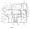
- FIG 1 there is seen a circuit diagram of the relevant part of a first embodiment of the semiconductor device.
- those parts which are identical with parts of the conventional semiconductor arrangement shown in Figure 5 are given the same numbers, and their relevant explanations are omitted for brevity.
- an IGBT 1 with a current-sensing function which is one example of a semiconductor element with a current-sensing function, has a control circuit 2.
- the IGBT 1 includes a collector terminal 6a as a first main electrode, an emitter terminal 6b as a second main electrode, a gate terminal 6c as a control electrode, and an output terminal 1b for a first current-sensing electrode 1a, as well as an output terminal 1d for a second current-sensing electrode 1c.
- This IGBT turns the device on and off according to the drive signal 7a received from a control circuit 2, causing a main current 6f to flow from the first main electrode terminal 6a to the second main electrode terminal 6b when the device is turned on, and turns the main current 6f off when the drive signal 7a switches to a turn-off signal.
- the sensing currents 1e and 1f which have values proportional to the main currents 6f, flow out from the first current sensing electrode la and the second current sensing electrode 1c, and these currents are led from the output terminals 1b and 1d externally of the IGBT 1.
- FIG. 2 is a plan view showing the construction of the aforementioned IGBT 1.
- the IGBT 1 has an emitter 63 with a large area formed on the surface of a semiconductor substrate 11.
- the surface on which this emitter is formed also has thereon a gate 64 and a first current-sensing electrode 66, as well as a second current-sensing electrode 67 with a substantially smaller area than that of the emitter 63.
- the collector is formed, as before, on the face opposite to the face on which the emitter 63 is located.
- the control circuit 2 has a first current-sensing resistor 72 added to the conventional control circuit 7 shown in Figure 5.
- the current-sensing resistor 72 generates a detection voltage V6, which is proportional to the flowing sensing current 1e, and is consequently proportional to the main current 6f. This detection voltage is applied to a comparator 741 in the main current turn-off command circuit 74.
- a second current-sensing resistor 72a which has a resistance value Rsa generates a second detection voltage V6a which is proportional to the flowing sensing current 1f, and is consequently proportional to the main current 6f.
- This second detection voltage V6a is applied to the base of the NPN transistor 751 in the main current control circuit 75.
- the main current turn-off command circuit 74 detects this condition and applies an output signal 7f to the drive circuit 71.
- the drive circuit 71 which receives this signal 7f then converts this output signal 7a to a low L level signal, and forces the IGBT 1 off.
- the value of the main current 6f increases abruptly because of a short-circuit failure and reaches the value I sct of the short-circuit current detection level, then the value of the second detection voltage V6a detected by the second current-sensing resistor 72a reaches the threshold voltage V th, and the transistor 751 turns on and the main current 6f decreases rapidly to a value that the IGBT 1 can tolerate.
- these two resistance values Rs and Rsa are the values found in the first and second current-sensing resistors 72 and 72a respectively, and they can be set independently of each other. Therefore, the current values I oc and I sct can also be set independently of each other.
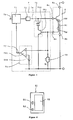
- FIG 3 there is seen a circuit diagram for the relevant part of a second embodiment of the semiconductor device.
- the parts identical to those of the conventional semiconductor shown in Figure 5 are given the same numbers, and their explanations are omitted.
- control circuit 4 for the IGBT 6 is disposed with a current-sensing resistor 5, which is different from the current-sensing resistor 72 used in conventional control circuits 7.
- the current-sensing resistor 5 is constituted by two resistors 51 and 52 connected in series, and having resistance values of Rs51 and Rs52 respectively.
- the sensing current 6g flows into this resistor 5 from the IGBT 6, the voltage drops V51 and V52 in proportion to the main current 6f are generated at the unit resistors 51 and 52.
- the voltage drop V51 is then applied to the comparator 741 in the main current turn-off command circuit 74 as a detection voltage of the main current 6f.
- the total of the voltage drops V51 and V52 is also applied to the base of the NPN transistor 751 in the main current control circuit 75 as the detection voltage of the main current 6f.
- the main current turn-off command circuit 74 detects this condition and applies a signal 7f to the drive circuit 71.
- the drive circuit 71 receiving the signal 7f converts this output signal 7a into a low-level L signal, and forces the IGBT 6 off.
- the transistor 751 turns on, and the main current 6f rapidly decreases to a value that the IGBT 6 can tolerate.
- the two resistance values Rs51 and Rs52 represent the resistance values in the two resistors 51 and 52, respectively, which can be set independently of each other. Therefore, the current values I oc and I sct can also be set independently of each other.
- FIG 4 there is seen a circuit diagram of the relevant part of a third semiconductor device according to the invention.
- the parts identical to the parts of the conventional semiconductor arrangement shown in Figure 5 are given the same numbers, and their explanations are omitted.
- the semiconductor device shown in Figure 4 differs from the aforementioned semiconductor device, which is shown in Figure 1, in that the semiconductor device of Figure 4 has two IGBTs 1.
- the two IGBTs 1 have their corresponding terminals 6a, 6b, 6c, 1b and 1d respectively connected to each other.
- the first current-sensing resistor 72 generates a first detection voltage V6 which is proportional to the total of the main currents 6f in the two IGBTs when the sum of the sensing currents 1e from the IGBTs 1 flows in.
- the second current-sensing resistor 72a generates the second detection voltage V6a that is in proportion to the total of the main currents 6f in the IGBTs when the sum of the sensing currents 1f from the two IGBTs 1 flows in.
- the two resistance values Rs and Rsa represent the resistance values in the first and second current-sensing resistors 72 and 72a, respectively. These values can be set independently of each other. Therefore, the current values (I oca + I ocb) and (I scta + I sctb) can also be set independently of each other.
- the ratio between the current values, (I oca + I ocb)/(I scta + I sctb) can therefore be varied by properly selecting the ratio between the resistance values, Rsa/Rs, even after the reference voltage E1 and threshold voltage V th have been determined.
- the IGBTs which have a main current-sensing function have been shown to have various current-sensing electrodes.
- the present invention should not be limited to this construction, but there need be only one current-sensing electrode for each IGBT as seen in the embodiment of Figure 3, and the electrodes may be connected in common, while only one current-sensing resistor need be disposed for each electrode connected in common.
- the IGBT described above is a semiconductor element with current-sensing function.
- a transistor of another type such as a MOSFET with current-sensing function for example, may also be used.
- the present invention either by disposing various current-sensing electrodes on a semiconductor element with a current-sensing function wherein signals corresponding to the sensing currents derived from each current-sensing electrode are applied independently into the main current turn-off command circuit and main current control circuit in a control circuit for the semiconductor element, or by constructing the current-sensing resistor in the control circuit with various unit resistors connected in series wherein a single sensing current flows into this resistor to generate various detection voltages divided by the resistor while detection voltages with different values are inputted independently into the main current turn-off command circuit and main current control circuit, the value I oc of the overcurrent detection level for the semiconductor element with a current-sensing function and the value (I sct) at the short-circuit current detection level can be set independently of each other.
Landscapes
- Electronic Switches (AREA)
- Power Conversion In General (AREA)
Applications Claiming Priority (2)
| Application Number | Priority Date | Filing Date | Title |
|---|---|---|---|
| JP04313825A JP3084982B2 (ja) | 1992-11-25 | 1992-11-25 | 半導体装置 |
| JP313825/92 | 1992-11-25 |
Publications (2)
| Publication Number | Publication Date |
|---|---|
| EP0599605A2 true EP0599605A2 (de) | 1994-06-01 |
| EP0599605A3 EP0599605A3 (de) | 1995-01-04 |
Family
ID=18045969
Family Applications (1)
| Application Number | Title | Priority Date | Filing Date |
|---|---|---|---|
| EP93309339A Withdrawn EP0599605A3 (de) | 1992-11-25 | 1993-11-23 | Halbleitervorrichtung mit Stropfühlerfunktion. |
Country Status (3)
| Country | Link |
|---|---|
| US (1) | US5396117A (de) |
| EP (1) | EP0599605A3 (de) |
| JP (1) | JP3084982B2 (de) |
Cited By (14)
| Publication number | Priority date | Publication date | Assignee | Title |
|---|---|---|---|---|
| EP0743751A2 (de) * | 1995-05-16 | 1996-11-20 | Fuji Electric Co., Ltd. | Halbleitervorrichtung |
| US6145107A (en) * | 1995-07-07 | 2000-11-07 | Siemens Aktiengesellschaft | Method for early failure recognition in power semiconductor modules |
| EP1054511A2 (de) * | 1999-04-27 | 2000-11-22 | DaimlerChrysler AG | Verfahren zur Überstromabschaltung eines Bipolartransistors mit isoliert angeordneter Gateelektrode (IGBT) und Vorrichtung zur Durchführung des Verfahrens |
| DE10154763A1 (de) * | 2001-11-09 | 2003-05-22 | Continental Teves Ag & Co Ohg | Verfahren und Schaltungsanordnung zur Erkennung eines Defekts von Halbleiterschaltelementen und deren Verwendung in elektronischen Bremskraft- und Fahrdynamikreglern |
| EP1349251A2 (de) * | 2000-07-24 | 2003-10-01 | Yazaki Corporation | Halbleiterschalter mit einem Multi-Source-Leistungs-FET mit Messstrompfad, bei dem eine bestimmte Anzahl an Einschaltversuchen vor dem endgültigen Ausschalten zulässig ist |
| WO2003052932A3 (en) * | 2001-12-18 | 2004-03-11 | Honeywell Int Inc | Short circuit protection for a driver |
| DE10158790B4 (de) * | 2001-05-28 | 2005-01-05 | Mitsubishi Denki K.K. | Halbleiterschutzschaltung |
| AU779845B2 (en) * | 1999-04-21 | 2005-02-17 | Biosceptre International Limited | A method for identifying pre-neoplastic and/or neoplastic states in mammals |
| FR2941338A1 (fr) * | 2009-01-20 | 2010-07-23 | Crouzet Automatismes | Commutateur statique haute tension |
| WO2015113672A1 (de) * | 2014-01-29 | 2015-08-06 | Robert Bosch Gmbh | Halbleiterschalter und verfahren zum bestimmen eines stroms durch einen halbleiterschalter |
| WO2015120934A1 (de) * | 2014-02-13 | 2015-08-20 | Robert Bosch Gmbh | Stromdetektionseinrichtung und verfahren zum erfassen eines elektrischen stroms |
| EP3035531A1 (de) * | 2014-12-17 | 2016-06-22 | Fuji Electric Co., Ltd. | Halbleiterbauelement und strombegrenzungsverfahren |
| DE10057486A1 (de) * | 2000-06-15 | 2016-10-13 | Continental Teves Ag & Co. Ohg | Verfahren und Schaltungsanordnung zur Erkennung eines Defekts von Halbleiterschaftelementen und dessen/deren Verwendung in Kraftfahrzeugen, insbesondere Bremskraft- und Fahrdynamikreglern |
| EP2439545A3 (de) * | 2010-10-08 | 2017-12-06 | Fuji Electric Co., Ltd. | Schaltung und Verfahren zur Leistungshalbleiterelementstromerkennung |
Families Citing this family (58)
| Publication number | Priority date | Publication date | Assignee | Title |
|---|---|---|---|---|
| JP3070360B2 (ja) * | 1993-10-28 | 2000-07-31 | 富士電機株式会社 | ダブルゲ−ト型半導体装置の制御装置 |
| JPH08503628A (ja) * | 1992-11-18 | 1996-04-23 | リポマトリクス インコーポレイテッド | 放射線治療用放射線透過性器官変位装置 |
| EP0639894B1 (de) * | 1993-08-18 | 1997-02-12 | Co.Ri.M.Me. Consorzio Per La Ricerca Sulla Microelettronica Nel Mezzogiorno | Schaltung zur Begrenzung des Maximalstroms, den ein Leistungstransistor an eine Last liefert |
| US5880624A (en) * | 1994-07-08 | 1999-03-09 | Kabushiki Kaisha Toshiba | Constant potential generating circuit and semiconductor device using same |
| GB9420572D0 (en) * | 1994-10-12 | 1994-11-30 | Philips Electronics Uk Ltd | A protected switch |
| GB9423076D0 (en) * | 1994-10-12 | 1995-01-04 | Philips Electronics Uk Ltd | A protected switch |
| EP0757443B1 (de) * | 1995-07-31 | 2006-03-08 | STMicroelectronics S.r.l. | Schaltung zum gesteuerten unabhängigen Verbrauchen von gespeicherter induktiver Energie mehrerer induktiver Lasten |
| US6100728A (en) * | 1995-07-31 | 2000-08-08 | Delco Electronics Corp. | Coil current limiting feature for an ignition coil driver module |
| US5642253A (en) * | 1995-07-31 | 1997-06-24 | Delco Electronics Corporation | Multi-channel ignition coil driver module |
| JP3373704B2 (ja) * | 1995-08-25 | 2003-02-04 | 三菱電機株式会社 | 絶縁ゲートトランジスタ駆動回路 |
| JP3149773B2 (ja) * | 1996-03-18 | 2001-03-26 | 富士電機株式会社 | 電流制限回路を備えた絶縁ゲートバイポーラトランジスタ |
| US5828261A (en) * | 1996-11-13 | 1998-10-27 | Caterpillar Inc. | Gate drive circuit that controls a power transistor in three states |
| JP2000022456A (ja) * | 1998-06-26 | 2000-01-21 | Nec Ic Microcomput Syst Ltd | 半導体集積回路 |
| US6169425B1 (en) * | 1998-09-29 | 2001-01-02 | Lucent Technologies Inc. | Voltage sensing current foldback switch circuit |
| US6194884B1 (en) * | 1999-11-23 | 2001-02-27 | Delphi Technologies, Inc. | Circuitry for maintaining a substantially constant sense current to load current ratio through an electrical load driving device |
| JP2001211059A (ja) * | 2000-01-26 | 2001-08-03 | Toshiba Corp | 半導体スイッチ素子の過電流保護回路 |
| US6717785B2 (en) | 2000-03-31 | 2004-04-06 | Denso Corporation | Semiconductor switching element driving circuit |
| JP3793012B2 (ja) * | 2000-09-21 | 2006-07-05 | 松下電器産業株式会社 | 負荷駆動装置 |
| JP4219567B2 (ja) | 2001-04-03 | 2009-02-04 | 三菱電機株式会社 | 半導体装置 |
| US7132868B2 (en) * | 2001-06-27 | 2006-11-07 | Mitsubishi Denki Kabushiki Kaisha | Semiconductor device |
| CA2385434C (en) * | 2002-04-01 | 2012-11-27 | S&C Electric Company | Control arrangement for power electronic system |
| JP2004312924A (ja) * | 2003-04-09 | 2004-11-04 | Mitsubishi Electric Corp | 半導体デバイスの駆動回路 |
| US7372685B2 (en) * | 2003-05-20 | 2008-05-13 | On Semiconductor | Multi-fault protected high side switch with current sense |
| JP4211741B2 (ja) * | 2005-01-27 | 2009-01-21 | 株式会社デンソー | 出力カットオフ回路 |
| DE102005045099B4 (de) * | 2005-09-21 | 2011-05-05 | Infineon Technologies Ag | Entsättigungsschaltung mit einem IGBT |
| ITVA20060001A1 (it) * | 2006-01-04 | 2007-07-05 | St Microelectronics Srl | Metodo per generare un segnale rappresentativo della corrente erogata ad un carico da un dispositvo di potenza e relativo dispositivo di potenza |
| JP2007288356A (ja) * | 2006-04-13 | 2007-11-01 | Auto Network Gijutsu Kenkyusho:Kk | 電力供給制御装置 |
| JP4925763B2 (ja) * | 2006-08-01 | 2012-05-09 | 三菱電機株式会社 | 半導体モジュール |
| JP4963891B2 (ja) * | 2006-08-01 | 2012-06-27 | ローム株式会社 | 負荷駆動回路 |
| JP4752811B2 (ja) * | 2007-06-06 | 2011-08-17 | 日産自動車株式会社 | 電圧駆動型素子の駆動回路 |
| DE102008045410B4 (de) * | 2007-09-05 | 2019-07-11 | Denso Corporation | Halbleitervorrichtung mit IGBT mit eingebauter Diode und Halbleitervorrichtung mit DMOS mit eingebauter Diode |
| JP5223758B2 (ja) * | 2009-04-06 | 2013-06-26 | 株式会社デンソー | 電力変換回路の駆動回路 |
| JP5747445B2 (ja) * | 2009-05-13 | 2015-07-15 | 富士電機株式会社 | ゲート駆動装置 |
| JP5115829B2 (ja) * | 2010-06-09 | 2013-01-09 | 株式会社デンソー | スイッチング装置 |
| JP5678498B2 (ja) * | 2010-07-15 | 2015-03-04 | 富士電機株式会社 | 電力用半導体素子のゲート駆動回路 |
| US8674727B2 (en) * | 2010-08-31 | 2014-03-18 | Infineon Technologies Austria Ag | Circuit and method for driving a transistor component based on a load condition |
| JP5675245B2 (ja) * | 2010-09-21 | 2015-02-25 | 矢崎総業株式会社 | 負荷駆動装置 |
| JP2012090435A (ja) * | 2010-10-20 | 2012-05-10 | Mitsubishi Electric Corp | 駆動回路及びこれを備える半導体装置 |
| JP5146555B2 (ja) * | 2011-02-28 | 2013-02-20 | 株式会社デンソー | スイッチング素子の駆動回路 |
| JP5430608B2 (ja) * | 2011-04-27 | 2014-03-05 | カルソニックカンセイ株式会社 | 半導体スイッチング素子駆動回路 |
| CN102905413B (zh) * | 2011-07-26 | 2014-11-05 | 桦晶科技股份有限公司 | 驱动高电压发光二极管灯泡的集成电路 |
| US8760218B2 (en) | 2012-05-07 | 2014-06-24 | General Electric Company | System and method for operating an electric power converter |
| JP5930954B2 (ja) * | 2012-12-14 | 2016-06-08 | 三菱電機株式会社 | パワーモジュール |
| US20150333505A1 (en) * | 2012-12-20 | 2015-11-19 | Telefonaktiebolaget L M Ericsson (Publ) | Method and Apparatus Relating to Surge Protection |
| JP6104660B2 (ja) * | 2013-03-21 | 2017-03-29 | 本田技研工業株式会社 | 短絡電流保護装置 |
| US9843181B2 (en) * | 2013-07-25 | 2017-12-12 | Infineon Technologies Austria Ag | Semiconductor device including a control circuit |
| JP6353648B2 (ja) * | 2013-12-10 | 2018-07-04 | 矢崎総業株式会社 | 半導体異常検出回路 |
| US9750328B2 (en) * | 2015-06-23 | 2017-09-05 | The North Face Apparel Corp. | Fastener systems |
| US10205313B2 (en) | 2015-07-24 | 2019-02-12 | Symptote Technologies, LLC | Two-transistor devices for protecting circuits from sustained overcurrent |
| CN108292837B (zh) | 2015-09-21 | 2020-01-17 | 西普托特技术有限责任公司 | 用于保护电路的单晶体管器件以及方法 |
| JP6544260B2 (ja) * | 2016-02-15 | 2019-07-17 | 株式会社デンソー | 電力変換装置 |
| JP6961944B2 (ja) * | 2017-01-18 | 2021-11-05 | 富士電機株式会社 | パワー半導体モジュール |
| WO2018158807A1 (ja) * | 2017-02-28 | 2018-09-07 | 三菱電機株式会社 | 半導体装置、および、電力変換システム |
| US10432186B2 (en) * | 2017-11-14 | 2019-10-01 | Ford Global Technologies, Llc | Variable resistance power switch feedback |
| JP6879188B2 (ja) * | 2017-12-19 | 2021-06-02 | トヨタ自動車株式会社 | 駆動装置の異常判定装置 |
| US10848053B2 (en) * | 2018-07-13 | 2020-11-24 | Kohler Co. | Robust inverter topology |
| US10756532B2 (en) | 2018-07-13 | 2020-08-25 | Kohler Co. | Ground fault minimization |
| JP7087869B2 (ja) * | 2018-09-18 | 2022-06-21 | 株式会社デンソー | 電力変換装置 |
Citations (4)
| Publication number | Priority date | Publication date | Assignee | Title |
|---|---|---|---|---|
| FR2635929A1 (fr) * | 1988-09-01 | 1990-03-02 | Fuji Electric Co Ltd | Dispositif a semi-conducteur possedant un circuit de protection contre les courts-circuits |
| EP0467681A2 (de) * | 1990-07-19 | 1992-01-22 | Fuji Electric Co., Ltd. | Treiberschaltung für einen Bipolartransistor mit isoliertem Gate mit Stromsonde |
| US5091664A (en) * | 1989-04-07 | 1992-02-25 | Fuji Electric Co., Ltd. | Insulated gate bipolar transistor circuit with overcurrent protection |
| EP0561386A1 (de) * | 1992-03-18 | 1993-09-22 | Fuji Electric Co., Ltd. | Halbleiteranordnung |
Family Cites Families (3)
| Publication number | Priority date | Publication date | Assignee | Title |
|---|---|---|---|---|
| FR2375722A1 (fr) * | 1976-12-21 | 1978-07-21 | Thomson Csf | Element logique a faible consommation |
| US4577125A (en) * | 1983-12-22 | 1986-03-18 | Advanced Micro Devices, Inc. | Output voltage driver with transient active pull-down |
| US5061863A (en) * | 1989-05-16 | 1991-10-29 | Kabushiki Kaisha Toyoda Jidoshokki Seisakusho | Transistor provided with a current detecting function |
-
1992
- 1992-11-25 JP JP04313825A patent/JP3084982B2/ja not_active Expired - Fee Related
-
1993
- 1993-11-23 EP EP93309339A patent/EP0599605A3/de not_active Withdrawn
- 1993-11-23 US US08/156,585 patent/US5396117A/en not_active Expired - Lifetime
Patent Citations (4)
| Publication number | Priority date | Publication date | Assignee | Title |
|---|---|---|---|---|
| FR2635929A1 (fr) * | 1988-09-01 | 1990-03-02 | Fuji Electric Co Ltd | Dispositif a semi-conducteur possedant un circuit de protection contre les courts-circuits |
| US5091664A (en) * | 1989-04-07 | 1992-02-25 | Fuji Electric Co., Ltd. | Insulated gate bipolar transistor circuit with overcurrent protection |
| EP0467681A2 (de) * | 1990-07-19 | 1992-01-22 | Fuji Electric Co., Ltd. | Treiberschaltung für einen Bipolartransistor mit isoliertem Gate mit Stromsonde |
| EP0561386A1 (de) * | 1992-03-18 | 1993-09-22 | Fuji Electric Co., Ltd. | Halbleiteranordnung |
Non-Patent Citations (1)
| Title |
|---|
| 3RD INTERNATIONAL SYMPOSIUM ON POWER SEMICONDUCTOR DEVICES AND ICS, 22 April 1991, BALTIMORE,US pages 248 - 253 H. MIYAZAKI ET. AL. 'A NOVEL HIGH VOLTAGE THREE PHASE MONOLITHIC INVERTER IC WITH TWO CURRENT LEVELS SENSING' * |
Cited By (24)
| Publication number | Priority date | Publication date | Assignee | Title |
|---|---|---|---|---|
| EP0743751A3 (de) * | 1995-05-16 | 1998-04-08 | Fuji Electric Co., Ltd. | Halbleitervorrichtung |
| EP0743751A2 (de) * | 1995-05-16 | 1996-11-20 | Fuji Electric Co., Ltd. | Halbleitervorrichtung |
| US6145107A (en) * | 1995-07-07 | 2000-11-07 | Siemens Aktiengesellschaft | Method for early failure recognition in power semiconductor modules |
| AU779845B2 (en) * | 1999-04-21 | 2005-02-17 | Biosceptre International Limited | A method for identifying pre-neoplastic and/or neoplastic states in mammals |
| EP1054511A2 (de) * | 1999-04-27 | 2000-11-22 | DaimlerChrysler AG | Verfahren zur Überstromabschaltung eines Bipolartransistors mit isoliert angeordneter Gateelektrode (IGBT) und Vorrichtung zur Durchführung des Verfahrens |
| EP1054511A3 (de) * | 1999-04-27 | 2002-02-06 | DaimlerChrysler Rail Systems GmbH | Verfahren zur Überstromabschaltung eines Bipolartransistors mit isoliert angeordneter Gateelektrode (IGBT) und Vorrichtung zur Durchführung des Verfahrens |
| DE10057486A1 (de) * | 2000-06-15 | 2016-10-13 | Continental Teves Ag & Co. Ohg | Verfahren und Schaltungsanordnung zur Erkennung eines Defekts von Halbleiterschaftelementen und dessen/deren Verwendung in Kraftfahrzeugen, insbesondere Bremskraft- und Fahrdynamikreglern |
| EP1349251A2 (de) * | 2000-07-24 | 2003-10-01 | Yazaki Corporation | Halbleiterschalter mit einem Multi-Source-Leistungs-FET mit Messstrompfad, bei dem eine bestimmte Anzahl an Einschaltversuchen vor dem endgültigen Ausschalten zulässig ist |
| EP1349251A3 (de) * | 2000-07-24 | 2006-09-13 | Yazaki Corporation | Halbleiterschalter mit einem Multi-Source-LeistungsFET mit Messstrompfad, bei dem eine bestimmte Anzahl an Einschaltversuchen vor dem endgültigen Ausschalten zulässig ist |
| DE10158790B4 (de) * | 2001-05-28 | 2005-01-05 | Mitsubishi Denki K.K. | Halbleiterschutzschaltung |
| DE10154763A1 (de) * | 2001-11-09 | 2003-05-22 | Continental Teves Ag & Co Ohg | Verfahren und Schaltungsanordnung zur Erkennung eines Defekts von Halbleiterschaltelementen und deren Verwendung in elektronischen Bremskraft- und Fahrdynamikreglern |
| US7027939B2 (en) | 2001-11-09 | 2006-04-11 | Continental Teves Ag&Co. Ohg | Method and circuit for detecting a fault of semiconductor circuit elements and use thereof in electronic regulators of braking force and of dynamics movement of vehicles |
| WO2003052932A3 (en) * | 2001-12-18 | 2004-03-11 | Honeywell Int Inc | Short circuit protection for a driver |
| FR2941338A1 (fr) * | 2009-01-20 | 2010-07-23 | Crouzet Automatismes | Commutateur statique haute tension |
| EP2209211A3 (de) * | 2009-01-20 | 2010-12-22 | Crouzet Automatismes | Statischer Hochspannungsschalter |
| EP2439545A3 (de) * | 2010-10-08 | 2017-12-06 | Fuji Electric Co., Ltd. | Schaltung und Verfahren zur Leistungshalbleiterelementstromerkennung |
| US9903905B2 (en) | 2014-01-29 | 2018-02-27 | Robert Bosch Gmbh | Semiconductor switch and method for determining a current through a semiconductor switch |
| CN105934886A (zh) * | 2014-01-29 | 2016-09-07 | 罗伯特·博世有限公司 | 半导体开关和用于确定通过半导体开关的电流的方法 |
| WO2015113672A1 (de) * | 2014-01-29 | 2015-08-06 | Robert Bosch Gmbh | Halbleiterschalter und verfahren zum bestimmen eines stroms durch einen halbleiterschalter |
| CN105934886B (zh) * | 2014-01-29 | 2019-07-12 | 罗伯特·博世有限公司 | 半导体开关和用于确定通过半导体开关的电流的方法 |
| WO2015120934A1 (de) * | 2014-02-13 | 2015-08-20 | Robert Bosch Gmbh | Stromdetektionseinrichtung und verfahren zum erfassen eines elektrischen stroms |
| US10013008B2 (en) | 2014-02-13 | 2018-07-03 | Robert Bosch Gmbh | Current detection device and method for sensing an electrical current |
| EP3035531A1 (de) * | 2014-12-17 | 2016-06-22 | Fuji Electric Co., Ltd. | Halbleiterbauelement und strombegrenzungsverfahren |
| US10103539B2 (en) | 2014-12-17 | 2018-10-16 | Fuji Electric Co., Ltd. | Semiconductor device and current limiting method |
Also Published As
| Publication number | Publication date |
|---|---|
| JPH06164344A (ja) | 1994-06-10 |
| US5396117A (en) | 1995-03-07 |
| EP0599605A3 (de) | 1995-01-04 |
| JP3084982B2 (ja) | 2000-09-04 |
Similar Documents
| Publication | Publication Date | Title |
|---|---|---|
| EP0599605A2 (de) | Halbleitervorrichtung mit Stropfühlerfunktion | |
| US4429339A (en) | AC Transistor switch with overcurrent protection | |
| KR900008276B1 (ko) | 2단계차단동작을이용한절연게이트바이폴라트랜지스터용보호회로 | |
| JP3193827B2 (ja) | 半導体パワーモジュールおよび電力変換装置 | |
| US5091664A (en) | Insulated gate bipolar transistor circuit with overcurrent protection | |
| US6717785B2 (en) | Semiconductor switching element driving circuit | |
| EP0369448B1 (de) | Treiberschaltung zur Verwendung bei einer spannungsgesteuerten Halbleitervorrichtung | |
| JP2837054B2 (ja) | 絶縁ゲート型半導体装置 | |
| US5123746A (en) | Bridge type power converter with improved efficiency | |
| EP0437108A2 (de) | Steuerschaltung zum Schalten eines Stromes in einer Last | |
| CN111033989A (zh) | 控制电路及电力转换装置 | |
| US6809561B2 (en) | Semiconductor power converting apparatus | |
| US4215279A (en) | Apparatus for controlling the operation of power transistors in a switching mode | |
| US5164874A (en) | Apparatus for protecting against overvoltage | |
| KR100225768B1 (ko) | 파워 소자 구동 회로(Power Element Driving Cirluit) | |
| JPH1032476A (ja) | 過電流保護回路 | |
| US5457419A (en) | MOSFET with temperature protection | |
| US5737200A (en) | Semiconductor device protection method | |
| EP0425035A2 (de) | Überlastschutz-Steuerschaltung für einen Leistungstransistor | |
| EP0700101B1 (de) | Relaisfotohalbleiter, Relaisfotohalbleitervorrichtung, Steuergerät mit Relaisfotohalbleitervorrichtung, Leistungsversorgungsvorrichtung mit Fotohalbleitervorrichtung und Schaltgerät mit Relaisfotohalbleitervorrichtung | |
| US5418674A (en) | Multi-lead protected power device having current and boot-strap inputs | |
| JP3764259B2 (ja) | インバータ装置 | |
| WO2023199840A1 (ja) | 半導体装置および過電流保護装置 | |
| JP2002110986A (ja) | 半導体装置 | |
| EP0789445B1 (de) | Elektrischer leistungswandler |
Legal Events
| Date | Code | Title | Description |
|---|---|---|---|
| PUAI | Public reference made under article 153(3) epc to a published international application that has entered the european phase |
Free format text: ORIGINAL CODE: 0009012 |
|
| AK | Designated contracting states |
Kind code of ref document: A2 Designated state(s): DE FR GB |
|
| 17P | Request for examination filed |
Effective date: 19940426 |
|
| PUAL | Search report despatched |
Free format text: ORIGINAL CODE: 0009013 |
|
| AK | Designated contracting states |
Kind code of ref document: A3 Designated state(s): DE FR GB |
|
| 17Q | First examination report despatched |
Effective date: 19960318 |
|
| STAA | Information on the status of an ep patent application or granted ep patent |
Free format text: STATUS: THE APPLICATION IS DEEMED TO BE WITHDRAWN |
|
| 18D | Application deemed to be withdrawn |
Effective date: 19960730 |