EP0596245A1 - Wirknadelanordnung und zugehörige Wirknadel - Google Patents
Wirknadelanordnung und zugehörige Wirknadel Download PDFInfo
- Publication number
- EP0596245A1 EP0596245A1 EP93115600A EP93115600A EP0596245A1 EP 0596245 A1 EP0596245 A1 EP 0596245A1 EP 93115600 A EP93115600 A EP 93115600A EP 93115600 A EP93115600 A EP 93115600A EP 0596245 A1 EP0596245 A1 EP 0596245A1
- Authority
- EP
- European Patent Office
- Prior art keywords
- knitting needle
- knitting
- arrangement according
- needle arrangement
- bar
- Prior art date
- Legal status (The legal status is an assumption and is not a legal conclusion. Google has not performed a legal analysis and makes no representation as to the accuracy of the status listed.)
- Granted
Links
Images


Classifications
-
- D—TEXTILES; PAPER
- D04—BRAIDING; LACE-MAKING; KNITTING; TRIMMINGS; NON-WOVEN FABRICS
- D04B—KNITTING
- D04B35/00—Details of, or auxiliary devices incorporated in, knitting machines, not otherwise provided for
- D04B35/02—Knitting tools or instruments not provided for in group D04B15/00 or D04B27/00
- D04B35/06—Sliding-tongue needles
-
- D—TEXTILES; PAPER
- D04—BRAIDING; LACE-MAKING; KNITTING; TRIMMINGS; NON-WOVEN FABRICS
- D04B—KNITTING
- D04B27/00—Details of, or auxiliary devices incorporated in, warp knitting machines, restricted to machines of this kind
- D04B27/06—Needle bars; Sinker bars
-
- D—TEXTILES; PAPER
- D04—BRAIDING; LACE-MAKING; KNITTING; TRIMMINGS; NON-WOVEN FABRICS
- D04B—KNITTING
- D04B35/00—Details of, or auxiliary devices incorporated in, knitting machines, not otherwise provided for
- D04B35/30—Devices for controlling temperature of machine parts
Definitions
- the invention relates to a knitting needle arrangement for warp knitting machines, in which the shafts of the knitting needles are arranged in parallel grooves of a needle bar, pressed against the groove base by means of a tension force and provided with a stop on the side facing the groove base, and to a knitting needle for use in a such a knitting needle arrangement.
- the knitting needle has a straight shaft which is received by the groove and which has an angled end at the foot which engages in a transverse recess in the bar.
- a cover plate which in turn is loaded by a clamping piece, covers the grooves and holds the needle shafts on the groove base.
- a plastic film is placed between the cover plate and the needle shafts.
- the invention is based on the object of specifying an improved knitting needle or knitting needle arrangement which enables the knitting needles to be fixed in a much more precise position.
- This object is achieved in that the clamping force is introduced into the knitting needles at an angle to the shaft axis deviating from 90 ° .
- This tension force results in a transverse force component transverse to the longitudinal axis of the shaft, by means of which the shaft is pressed against the base of the groove, and a longitudinal force component, which extends in the longitudinal direction of the shaft, by means of which the stop is held against a bar-proof abutment.
- the shear force component in question can therefore be small. A shift of the knitting needles due to deformation of the needle bar or a cover plate is therefore not to be feared. Rather, lighter and therefore cheaper needle bars can be used without impairing the positional accuracy of the knitting needles.
- the force application angle can be less than 30 and in particular 5 to 15.
- Tension is expediently introduced at a defined point on the shaft. It is therefore recommended that the shaft has a force introduction projection protruding from the groove. A tensioning force can also act on such a projection, which only forms a small angle with the longitudinal axis of the shaft.
- the removal of the unavoidable heat from the knitting needles is significantly improved, since the needle no longer has to be covered over a large part of its length by a plastic film or a cover plate, but is exposed to the free circulation of air.
- the stop advantageously has an oblique stop surface which interacts with a corresponding, bar-resistant abutment surface.
- the sloping stop surface has a component in the direction of the shaft axis. There is a kind of wedge effect, through which the longitudinal force component in turn helps to push the shaft against the bottom of the groove. Overall, with a low clamping force, there is a high level of positional security.
- the stop on the needle foot and the force introduction projection are advantageously arranged axially offset from the stop. This also results in a torque, which favors the securing of the position.
- a clamping element with an outwardly convex cross section is recommended, which extends between support surfaces on the knitting needles and a bar-fixed support surface and can be expanded by means of a clamping screw.
- Such a clamping element has a very low installation height and can be designed with a relatively small wall thickness.
- the clamping screw can have a collar which interacts with the bar to determine the clamping force. If you screw in the screw up to the collar, a defined clamping force results. There is no risk of excessive forces being applied that could deform the needle bar.
- the bar cross-section between the bar-fixed support surface and the rear of the groove can have an elevation.
- the needle bar can be formed by a hollow profile having at least one cavity. This not only leads to a light and cheaper component, but also enables improved heat dissipation from the needle bar.
- a knitting needle for use in the knitting needle arrangement described above is characterized in that the shaft has a force introduction projection on one side and an inclined contact surface on the other side.
- a knitting needle bar 1 is designed as a hollow profile 2, which has two cavities 4 and 5 separated by a thin wall 3.
- Knitting needles 6 are inserted in parallel grooves 7 of the needle bar 1 in such a way that the shank 8 of the needle rests with the front 9 against the base of the groove and projects with the back 10 out of the groove.
- the knitting needle 6 is a slide needle with a hook 11 and has a groove 12 into which a slide, not shown, engages to close the hook space.
- the knitting needle 6 has on the needle foot a projection 13 which is provided with an oblique stop surface 14 which cooperates with a corresponding abutment surface 15 on the needle bar 1.
- This abutment surface 15 forms with the front 9 of the shaft 8 an acute angle which, when a longitudinal force is applied to the knitting needle 6, causes the front 9 of the shaft to bear against the base of the groove.
- a force introduction projection 16 is attached approximately in the middle of the shaft 8 and is located outside the groove 7.
- Each projection 16 has a support surface 17.
- the needle bar has a support surface 18.
- tensioning elements are distributed next to each other over the length of the needle bar.
- Each tensioning element is tensioned by means of a screw 20, the thread 21 of which engages in a threaded bore 22 of the needle bar 1.
- By tightening the tensioning element is brought from the starting position shown in dash-dotted lines to the fully extended end position. This is defined in that the screw 20 has a collar 23 which, when screwed down, bears against a surface 24 of the needle bar.
- a force is transmitted to the knitting needle 6. This force is limited by the installation of the federal government 23 on the area 24.
- the same reference numerals are used for identical parts and reference numerals increased by 100 for modified parts. It is essentially different that the needle bar 101 does not have a hollow profile but a full profile and that in order to increase the rigidity, the cross section of the needle bar 101 has an elevation 25 between the groove 7 and the bar-fixed support surface 118. This also leads to a shortening of the collar 123 of the clamping screw 120.
- FIG. 3 for the knitting needle 6, which is similar to the needles of FIGS. 1 and 2, it is illustrated how the tensioning force P exerted by the tensioning element 19 acts. It is at an angle a to the longitudinal axis 26 of the knitting needle 6.
- the force acting in the needle is broken down into a longitudinal force component P L and a transverse force component P o .
- the longitudinal force component P L ensures that the oblique stop surface 14 comes to rest on the abutment surface 15 and the axial position of the needle 6 is thereby positively fixed.
- a wedge-shaped space 27 is formed, which ensures that the front 9 is pressed against the groove base when the longitudinal force component P L occurs.
- the shear force component P o also serves as a pressing force. Because the support surface 17 is axially offset from the stop surface 14, it also gives a torque about the pivot point 28, which supports the pressing action. Because of these conditions, a relatively small force P is sufficient to hold the needle 6 securely in a defined position.
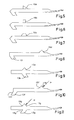
- FIG. 4 shows a knitting needle 216 for a Raschel machine.
- the rear side 210 of the shaft 208 lies against the base of the groove.
- the projection 213 is on the rear side 210 and the force introduction projection 216 is on the front side 209 the needle.
- the clamping force P is again indicated by an arrow.
- the force application protrusion 16 has the shape of an isosceles triangle
- the force application protrusion 16a in FIG. 5 has the shape of a right triangle
- the force application protrusion 16b in FIG. 6 has the shape of a square
- the force application protrusion 16c in FIG 7 the shape of a semicircle.
- the stop 13e and the force introduction projection 16e can also be arranged without axial displacement.
- the tension force P acts essentially in the opposite direction. Accordingly, the support surface 17f or 17g is provided on the side of the force introduction projection 16f or 16g facing the hook. With these needles, the slope of the stop surfaces 14f and 14g on the stops 13f and 13g is opposite to the slope in the previous figures.
Landscapes
- Engineering & Computer Science (AREA)
- Textile Engineering (AREA)
- Knitting Machines (AREA)
Abstract
Description
- Die Erfindung bezieht sich auf eine Wirknadelanordnung für Kettenwirkmaschinen, bei der die Schäfte der Wirknadeln in parallelen Nuten einer Nadelbarre angeordnet, mittels einer Spannkraft gegen den Nutengrund gedrückt und auf der dem Nutengrund zugewandten Seite mit einem Anschlag versehen sind sowie auf eine Wirknadel zur Verwendung bei einer solchen Wirknadelanordnung.
- Bei einer bekannten Wirknadelanordnung dieser Art (DE-GM 71 13 944) besitzt die Wirknadel einen geraden, von der Nut aufgenommenen Schaft, der am Fuß ein abgewinkeltes Ende besitzt, das in eine querlaufende Vertiefung der Barre greift. Eine Deckplatte, die ihrerseits durch ein Klemmstück belastet ist, überdeckt die Nuten und hält die Nadelschäfte am Nutengrund. Zwischen Deckplatte und Nadelschäfte ist eine Kunststoffolie gelegt.
- Bei dieser Konstruktion ist eine spielfreie Festlegung der Axiallage der Wirknadel nur möglich, wenn der Schaft mit großer Kraft gegen den Nutengrund gedrückt wird, so daß die Reibung eine axiale Verschiebung verhindert. Die zur Erzielung der kraftschlüssigen Verbindung aufzubringenden Spannkräfte sind so groß, daß sich Deckplatte und/oder Nadelbarre verformen, sofern sie nicht sehr stabil und damit groß und schwer ausgeführt werden. Die Verformung hat unter anderem zur Folge, daß die Hubbewegung der Legebarren vergrößert werden muß, daß die Gefahr einer Kollision zwischen Wirknadeln und Legenadeln besteht und - bei einer Schiebernadel - daß der Schieber an der Wirknadel aufläuft und infolge starker Reibung Wärme entsteht.
- Ein anderer Nachteil der bekannten Konstruktion liegt darin, daß die Wärme, die im Betrieb im Bereich der Wirknadeln entsteht, nur einseitig über die Barre abgeführt werden kann, weil die Kunststoffolie einen Wärmeabfluß zur Deckplatte hin verhindert. Dies führt zu weiteren störenden Verformungen der Barre.
- Der Erfindung liegt die Aufgabe zugrunde, eine verbesserte Wirknadel bzw. Wirknadelanordnung anzugeben, die eine sehr viel genauere Lagefixierung der Wirknadeln ermöglicht.
- Diese Aufgabe wird erfindungsgemäß dadurch gelöst, daß die Spannkraft in einem von 90 ° abweichenden Winkel zur Schaftachse in die Wirknadeln eingeleitet wird. Diese Spannkraft ergibt eine Querkraftomponente quer zur Schaftlängsachse, durch die der Schaft gegen den Nutengrund gedrückt wird, und eine sich in Schaftlängsrichtung erstreckende Längskraftkomponente, durch die der Anschlag gegen ein barrenfestes Widerlager gehalten wird. Damit ergibt sich eine formschlüssige Festlegung der Axiallage der Wirknadel. Für diese Festlegung ist keine kraftschlüssige Verbindung mehr erforderlich. Die betreffende Querkraftkomponente kann daher klein sein. Eine Verlagerung der Wirknadeln durch Verformung der Nadelbarre oder einer Deckplatte ist somit nicht zu befürchten. Vielmehr können leichtere und daher billigere Nadelbarren ohne Beeinträchtigung der Lagegenauigkeit der Wirknadeln verwendet werden.
- Um die Querkraftkomponente tatsächlich möglichst klein zu halten, kann der Kraftangriffswinkel kleiner als 30 sein und insbesondere 5 bis 15 betragen.
- Spannkraft wird zweckmäßig an einer definierten Stelle des Schafts eingeleitet. Daher empfiehlt es sich, daß der Schaft einen aus der Nut herausragenden Krafteinleitungs-Vorsprung trägt. An einem solchen Vorsprung kann auch eine Spannkraft angreifen, die nur einen kleinen Winkel mit der Schaftlängsachse bildet.
- Die Abfuhr der unvermeidbaren Wärme von den Wirknadeln ist wesentlich verbessert, da die Nadel nicht mehr über einen großen Teil ihrer Länge durch eine Kunststoffolie oder eine Deckplatte abgedeckt zu werden braucht, sondern der freien Luftzirkulation ausgesetzt ist.
- Mit Vorteil weist der Anschlag eine schräge Anschlagfläche auf, die mit einer korrespondierenden, barrenfesten Widerlagerfläche zusammenwirkt. Die schräge Anschlagfläche besitzt eine Komponente in Richtung der Schaftachse. Es ergibt sich eine Art Keilwirkung, durch welche die Längskraftkomponente ihrerseits dazu beiträgt, den Schaft gegen den Nutengrund zu drücken. Insgesamt ergibt sich mit einer geringen Spannkraft eine hohe Lagesicherheit.
- Mit Vorteil ist der Anschlag am Nadelfuß und der Krafteinleitungs-Vorsprung axial zum Anschlag versetzt angeordnet. Dies ergibt zusätzlich ein Drehmoment, das die Lagesicherung begünstigt.
- Zur Aufbringung der Spannkraft empfiehlt sich ein Spannelement mit nach außen konvexem Querschnitt, das sich zwischen Stützflächen an den Wirknadeln und einer barrenfesten Stützfläche erstreckt und mittels einer Spannschraube spreizbar ist. Ein solches Spannelement hat eine sehr geringe Einbauhöhe und kann mit verhältnismäßig geringer Wandstärke ausgeführt werden.
- Insbesondere kann die Spannschraube zur Festlegung der Spannkraft einen mit der Barre zusammenwirkenden Bund besitzen. Wenn man die Schraube bis zum Bund einschraubt, ergibt sich eine definierte Spannkraft. Es besteht keine Gefahr, daß übermäßige Kräfte aufgebracht werden, die zu einer Verformung der Nadelbarre führen könnten.
- In weiterer Ausgestaltung kann der Barrenquerschnitt zwischen barrenfester Stützfläche und Rückseite der Nut eine Erhebung aufweisen. Hierdurch ergibt sich eine höhere Steifigkeit der Nadelbarre, ohne daß zusätzlicher Platz benötigt wird.
- Da wesentlich geringere Kräfte als bisher auftreten, kann die Nadelbarre durch ein mindestens einen Hohlraum aufweisendes Hohlprofil gebildet sein. Dies führt nicht nur zu einem leichten und billigeren Bauteil, sondern ermöglicht auch eine verbesserte Wärmeabfuhr von der Nadelbarre.
- Eine Wirknadel zur Verwendung bei der zuvor beschriebenen Wirknadelanordnung ist dadurch gekennzeichnet, daß der Schaft auf der einen Seite einen Krafteinleitungs-Vorsprung und auf der anderen Seite eine schräge Anlagefläche aufweist.
- Die Erfindung wird nachstehend anhand in der Zeichnung dargestellter bevorzugter Ausführungsbeispiele näher erläutert. Es zeigen:
- Fig. 1 eine Seitenansicht, teilweise im Schnitt, einer Nadelbarre mit Wirknadel und ihrer Halterung gemäß der Erfindung,
- Fig. 2 eine abgewandelte Form einer Wirknadelanordnung gemäß der Erfindung,
- Fig. 3 eine Wirknadel ähnlich derjenigen der Ausführungsbeispiele der Fig. 1 und 2 und
- Fig. 4 bis 11 weitere Ausführungsformen der Wirknadel.
- Eine Wirknadelbarre 1 ist als Hohlprofil 2 ausgebildet, das zwei durch eine dünne Wand 3 getrennte Hohlräume 4 und 5 aufweist.
- Wirknadeln 6 sind in parallelen Nuten 7 der Nadelbarre 1 derart eingelegt, daß der Schaft 8 der Nadel mit der Vorderseite 9 am Nutengrund anliegt und mit der Rückseite 10 aus der Nut vorsteht. Die Wirknadel 6 ist eine Schiebernadel mit einem Haken 11 und besitzt eine Nut 12, in die ein nicht veranschaulichter Schieber zum Verschließen des Hakenraums eingreift.
- Die Wirknadel 6 besitzt am Nadelfuß einen Vorsprung 13, der mit einer schrägen Anschlagfläche 14 versehen ist, die mit einer korrespondierenden Widerlagerfläche 15 an der Nadelbarre 1 zusammenwirkt. Diese Widerlagerfläche 15 bildet mit der Vorderseite 9 des Schaftes 8 einen spitzen Winkel der beim Aufbringen einer Längskraft auf die Wirknadel 6 bewirkt, daß sich die Vorderseite 9 des Schafts gegen den Nutengrund anlegt.
- Ein Krafteinleitungs-Vorsprung 16 ist etwa in der Mitte des Schafts 8 angebracht und befindet sich außerhalb der Nut 7. Jeder Vorsprung 16 trägt eine Stützfläche 17. Die Nadelbarre weist eine Stützfläche 18 auf. Zwischen beiden erstreckt sich ein Spannelement 19, das aus einer Blechplatte besteht und einen nach außen konvex gewölbten Querschnitt besitzt.
- Derartige Spannelemente sind nebeneinander über die Länge der Nadelbarre verteilt. Jedes Spannelement wird mittels einer Schraube 20, deren Gewinde 21 in eine Gewindebohrung 22 der Nadelbarre 1 greift, gespannt. Durch das Festziehen wird das Spannelement aus der strichpunktiert gezeichneten Anfangsstellung in die vollausgezogene Endstellung gebracht. Diese ist dadurch definiert, daß die Schraube 20 einen Bund 23 aufweist, der sich beim Festschrauben gegen eine Fläche 24 der Nadelbarre anlegt. Durch das Spreizen des Spannelements 19 wird eine Kraft auf die Wirknadel 6 übertragen. Diese Kraft ist durch die Anlage des Bundes 23 an der Fläche 24 begrenzt.
- Bei der Ausführungsform nach Fig. 2 sind für identische Teile dieselben Bezugszeichen und für abgewandelte Teile um 100 erhöhte Bezugszeichen verwendet. Unterschiedlich ist es im wesentlichen, daß die Nadelbarre 101 kein Hohlprofil, sondern ein Vollprofil besitzt und daß zur Erhöhung der Steifigkeit der Querschnitt der Nadelbarre 101 zwischen der Nut 7 und der barrenfesten Stützfläche 118 eine Erhebung 25 aufweist. Dies führt auch zu einer Verkürzung des Bundes 123 der Spannschraube 120.
- In Fig. 3 ist für die Wirknadel 6, die den Nadeln der Fig. 1 und 2 ähnlich ist, veranschaulicht, wie die vom Spannelement 19 ausgeübte Spannkraft P wirkt. Sie steht in einem Winkel a zur Längsachse 26 der Wirknadel 6. Die in der Nadel wirkende Kraft ist in eine Längskraftkomponente PL und in eine Querkraftkomponente Po zerlegt. Die Längskraftkomponente PL sorgt dafür, daß die schräge Anschlagfläche 14 an der Widerlagerfläche 15 zur Anlage kommt und dadurch die axiale Lage der Nadel 6 formschlüssig festgelegt ist. Zwischen Anschlagfläche 14 und Vorderseite 9 wird ein keilförmiger Raum 27 gebildet, der dafür sorgt, daß beim Auftreten der Längskraftkomponente PL die Vorderseite 9 gegen den Nutengrund gedrückt wird. Da sich die Anschlagfläche 14 und die Stützfläche 17 auf einander gegenüberliegenden Seiten der Nadellängsachse 26 befinden, entsteht ein Drehmoment um einen etwa bei 28 liegenden Drehpunkt, das zusätzlich die Vorderseite 9 gegen den Nutengrund drückt. Die Querkraftkomponente Po dient ebenfalls als Andrückkraft. Weil die Stützfläche 17 axial gegenüber der Anschlagfläche 14 versetzt ist, ergibt auch sie ein Drehmoment um den Drehpunkt 28, das die Andrückwirkung unterstützt. Wegen dieser Verhältnisse genügt eine relativ geringe Kraft P, um die Nadel 6 sicher in einer definierten Lage zu halten.
- Während sich die Fig. 1 bis 3 auf die Wirknadelanordnung eines Kettstuhls beziehen, zeigt Fig. 4 eine Wirknadel 216 für eine Raschelmaschine. Bei ihr liegt die Rückseite 210 des Schaftes 208 an dem Nutengrund an. Demzufolge befindet sich der Vorsprung 213 an der Rückseite 210 und der Krafteinleitungs-Vorsprung 216 an der Vorderseite 209 der Nadel. Die Spannkraft P ist wiederum durch einen Pfeil angedeutet.
- Die Fig. 5, 6 und 7 zeigen, daß die Form der Krafteinleitungs-Vorsprünge und damit auch der Verlauf der Stützfläche unterschiedlich sein kann. Während der Krafteinleitungs-Vorsprung 16 die Form eines gleichschenkligen Dreiecks hat, hat der Krafteinleitungs-Vorsprung 16a in Fig. 5 die Form eines rechtwinkligen Dreiecks, der Krafteinleitungs-Vorsprung 16b in Fig. 6 die Form eines Quadrats und der Krafteinleitungs-Vorsprung 16c in Fig. 7 die Form eines Halbkreises. In vielen Fällen empfiehlt es sich, die Stützfläche 17 etwa rechtwinklig zur Richtung der Kraft P verlaufen zu lassen.
- Bei der Wirknadel der Fig. 8 ist unter Beibehaltung des Anschlags 13 der Krafteinleitungs-Vorsprung 16d mit größerem axialem Abstand von diesem angeordnet, was zu einem größeren Drehmoment führt.
- Wie Fig. 9 zeigt, können Anschlag 13e und Krafteinleitungs-Vorsprung 16e auch ohne axiale Versetzung angeordnet werden.
- Bei den Nadeln der Fig. 10 und 11 wirkt die Spannkraft P im wesentlichen in entgegengesetzter Richtung. Demzufolge ist die Stützfläche 17f bzw. 17g auf der dem Haken zugewandten Seite des Krafteinleitungs-Vorsprunges 16f bzw. 16g vorgesehen. Bei diesen Nadeln verläuft die Schräge der Anschlagflächen 14f bzw. 14g an den Anschlägen 13f bzw. 13g entgegengesetzt zu der Schräge in den vorangehenden Figuren.
- Bei den Fig. 9 und 11 empfiehlt es sich, die Nut auch zwischen dem Anschlag 13e bzw. 13g und dem Fußende der Nadel fortzusetzen.
Claims (11)
Applications Claiming Priority (2)
| Application Number | Priority Date | Filing Date | Title |
|---|---|---|---|
| DE4237084A DE4237084C2 (de) | 1992-11-03 | 1992-11-03 | Wirknadelanordnung und zugehörige Wirknadel |
| DE4237084 | 1992-11-03 |
Publications (2)
| Publication Number | Publication Date |
|---|---|
| EP0596245A1 true EP0596245A1 (de) | 1994-05-11 |
| EP0596245B1 EP0596245B1 (de) | 1997-03-05 |
Family
ID=6471990
Family Applications (1)
| Application Number | Title | Priority Date | Filing Date |
|---|---|---|---|
| EP93115600A Expired - Lifetime EP0596245B1 (de) | 1992-11-03 | 1993-09-28 | Wirknadelanordnung und zugehörige Wirknadel |
Country Status (5)
| Country | Link |
|---|---|
| US (1) | US5373710A (de) |
| EP (1) | EP0596245B1 (de) |
| JP (1) | JP2665447B2 (de) |
| KR (1) | KR960006357B1 (de) |
| DE (2) | DE4237084C2 (de) |
Cited By (3)
| Publication number | Priority date | Publication date | Assignee | Title |
|---|---|---|---|---|
| EP1813703A1 (de) * | 2006-01-25 | 2007-08-01 | Groz-Beckert KG | Wirknadel und Barre für diese |
| CN104005171A (zh) * | 2013-02-22 | 2014-08-27 | 卡尔迈尔纺织机械制造有限公司 | 塑料-成圈工具梳栉 |
| CN109267227A (zh) * | 2018-11-01 | 2019-01-25 | 江苏理工学院 | 混杂纤维空心脱圈针床 |
Families Citing this family (9)
| Publication number | Priority date | Publication date | Assignee | Title |
|---|---|---|---|---|
| EP1600543B1 (de) * | 2004-05-27 | 2008-04-09 | KARL MAYER TEXTILMASCHINENFABRIK GmbH | Wirkwerkzeug-Barre |
| EP1988199B1 (de) * | 2007-05-03 | 2009-10-28 | Groz-Beckert KG | Wirkmaschinenwerkzeug, insbesondere für feinste Teilung |
| DE502007003001D1 (de) * | 2007-05-03 | 2010-04-15 | Groz Beckert Kg | Werkzeugsatz und Barre für eine Wirkmaschine |
| CN101985792A (zh) * | 2010-12-03 | 2011-03-16 | 常德纺织机械有限公司 | 一种经编机用织针 |
| CN103266411A (zh) * | 2013-05-28 | 2013-08-28 | 马骏 | 一种嵌入型可拆卸活动主针针夹及针块 |
| CN105603627A (zh) * | 2015-12-16 | 2016-05-25 | 无锡吉进环保科技有限公司 | 一种可拆卸式防松经编机针床 |
| CN107663710A (zh) * | 2017-11-15 | 2018-02-06 | 常德纺织机械有限公司 | 碳纤维针床槽针压板 |
| ES2927820T3 (es) * | 2020-11-06 | 2022-11-11 | Karl Mayer Stoll R&D Gmbh | Barra de herramientas de género de punto para una máquina de punto por urdimbre |
| CN114182427B (zh) * | 2021-12-29 | 2023-03-31 | 福建航港针织品有限公司 | 一种具有双面固定的针床机构的高速经编机 |
Citations (4)
| Publication number | Priority date | Publication date | Assignee | Title |
|---|---|---|---|---|
| DE7113944U (de) * | 1971-07-22 | Mayer K Gmbh | · Vorrichtung zur Halterung der Nadeln von Kettenwirkmaschinen | |
| GB2139650A (en) * | 1983-05-05 | 1984-11-14 | Terrot Strickmaschinen Gmbh | Device for compensating for differences in thermal expansion in circular knitting machines |
| EP0193359A1 (de) * | 1985-02-27 | 1986-09-03 | Nakagawa Seisakusho Co.,Ltd | Zungennadel und Nadelblock für Raschelwirkmaschine |
| DE4111108A1 (de) * | 1991-04-05 | 1992-10-08 | Erbsloeh Julius & August | Als geschlossenes hohlprofil aus verstaerktem kunststoff ausgebildeter traeger |
Family Cites Families (11)
| Publication number | Priority date | Publication date | Assignee | Title |
|---|---|---|---|---|
| US601281A (en) * | 1898-03-29 | Island | ||
| US793556A (en) * | 1904-10-15 | 1905-06-27 | Tompkins Brothers Company | Needle-cap for knitting-machines. |
| US834598A (en) * | 1905-12-06 | 1906-10-30 | Berthold Wiener | Knitting-machine needle and holder therefor. |
| FR741233A (de) * | 1931-07-27 | 1933-02-08 | ||
| US1326555A (en) * | 1917-11-30 | 1919-12-30 | George A Wilkins | Needle-mount. |
| US1916676A (en) * | 1931-09-24 | 1933-07-04 | Lange George | Holder and needle for knitting machines |
| JPS416205Y1 (de) * | 1965-04-13 | 1966-03-30 | ||
| DE1760139B1 (de) * | 1968-04-09 | 1970-07-16 | Liebrandt Karl | Halterung von Wirkwerkzeugen |
| DE6811261U (de) * | 1968-12-13 | 1969-04-10 | Karl Liebrandt | Nadelhalterung fuer wirkmaschinen |
| JPS59132471A (ja) * | 1983-01-20 | 1984-07-30 | Olympus Optical Co Ltd | カセツトテ−プとカセツトケ−ス |
| DE3509214A1 (de) * | 1985-03-14 | 1986-09-25 | Liba Maschinenfabrik Gmbh, 8674 Naila | Nadelbarre einer kettenwirkmaschine |
-
1992
- 1992-11-03 DE DE4237084A patent/DE4237084C2/de not_active Expired - Fee Related
-
1993
- 1993-09-28 EP EP93115600A patent/EP0596245B1/de not_active Expired - Lifetime
- 1993-09-28 DE DE59305595T patent/DE59305595D1/de not_active Expired - Fee Related
- 1993-10-27 US US08/144,149 patent/US5373710A/en not_active Expired - Fee Related
- 1993-10-29 JP JP5272079A patent/JP2665447B2/ja not_active Expired - Lifetime
- 1993-11-02 KR KR93023106A patent/KR960006357B1/ko not_active Expired - Fee Related
Patent Citations (4)
| Publication number | Priority date | Publication date | Assignee | Title |
|---|---|---|---|---|
| DE7113944U (de) * | 1971-07-22 | Mayer K Gmbh | · Vorrichtung zur Halterung der Nadeln von Kettenwirkmaschinen | |
| GB2139650A (en) * | 1983-05-05 | 1984-11-14 | Terrot Strickmaschinen Gmbh | Device for compensating for differences in thermal expansion in circular knitting machines |
| EP0193359A1 (de) * | 1985-02-27 | 1986-09-03 | Nakagawa Seisakusho Co.,Ltd | Zungennadel und Nadelblock für Raschelwirkmaschine |
| DE4111108A1 (de) * | 1991-04-05 | 1992-10-08 | Erbsloeh Julius & August | Als geschlossenes hohlprofil aus verstaerktem kunststoff ausgebildeter traeger |
Cited By (6)
| Publication number | Priority date | Publication date | Assignee | Title |
|---|---|---|---|---|
| EP1813703A1 (de) * | 2006-01-25 | 2007-08-01 | Groz-Beckert KG | Wirknadel und Barre für diese |
| US7549304B2 (en) | 2006-01-25 | 2009-06-23 | Groz-Beckert Kg | Knitting needle and bar for said needle |
| CN104005171A (zh) * | 2013-02-22 | 2014-08-27 | 卡尔迈尔纺织机械制造有限公司 | 塑料-成圈工具梳栉 |
| CN104005171B (zh) * | 2013-02-22 | 2016-03-16 | 卡尔迈尔纺织机械制造有限公司 | 塑料-成圈工具梳栉 |
| CN109267227A (zh) * | 2018-11-01 | 2019-01-25 | 江苏理工学院 | 混杂纤维空心脱圈针床 |
| CN109267227B (zh) * | 2018-11-01 | 2020-02-14 | 江苏理工学院 | 混杂纤维空心脱圈针床 |
Also Published As
| Publication number | Publication date |
|---|---|
| KR940011685A (ko) | 1994-06-21 |
| KR960006357B1 (en) | 1996-05-15 |
| EP0596245B1 (de) | 1997-03-05 |
| DE4237084C2 (de) | 1995-04-13 |
| US5373710A (en) | 1994-12-20 |
| DE4237084A1 (de) | 1994-05-05 |
| JPH06207355A (ja) | 1994-07-26 |
| JP2665447B2 (ja) | 1997-10-22 |
| DE59305595D1 (de) | 1997-04-10 |
Similar Documents
| Publication | Publication Date | Title |
|---|---|---|
| EP0557248B1 (de) | Spannleiste zur Verwendung in einer Einspannvorrichtung für auf einer Werkzeugmaschine zu bearbeitende Werkstücke | |
| EP0095062B1 (de) | Spanabhebendes Werkzeug mit geklemmtem Schneideinsatz | |
| EP0596245B1 (de) | Wirknadelanordnung und zugehörige Wirknadel | |
| DE1278305B (de) | Trag- und Belastungsarm fuer Streckwerke von Spinnereimaschinen | |
| EP2048271A1 (de) | Wirkwerkzeuganordnung und Wirkwerkzeugverbund | |
| DE69207876T2 (de) | Bauelement | |
| DE19750055C2 (de) | Fliesenschneidgerät | |
| EP0010260B1 (de) | Schraubzwinge | |
| DE3143743C2 (de) | Schiebernadel für Kettenwirkmaschinen | |
| DE1523857B2 (de) | Vorrichtung zum befestigen der spiralfeder eines uhrwerks | |
| DE102018206849B4 (de) | Vorrichtung zur klemmenden Befestigung | |
| DE3420693A1 (de) | Einspannvorrichtung fuer haekelnadeln | |
| DE4030372C1 (en) | Electrical component plug-in housing - has two projections on locating foot separated by variable distance to fit gap | |
| DE8214831U1 (de) | Stechwerkzeug mit geklemmtem Schneideinsatz | |
| EP0510399B1 (de) | Halter für Andruckspindeln an Spannvorrichtungen | |
| DE19847973C1 (de) | Vorschubeinrichtung zum schrittweisen Werkstücktransport in Produktionsmaschinen | |
| DE974150C (de) | Streckwerk fuer Spinnereimaschinen | |
| DE3111250C2 (de) | Zeichenlineal für Zeichenplatten | |
| EP3336275B1 (de) | Markisentuch-fixier- und -führungseinrichtung | |
| DE3400502C2 (de) | Elektrisches Relais | |
| DE2741292C2 (de) | Tastenschalter | |
| EP0949011B1 (de) | Handgetätigtes Austraggerät mit einer auf eine Schubstange wirkenden Reibungsbremse | |
| DE2719066C3 (de) | Nockeneinrichtung | |
| DE3322775C2 (de) | ||
| DE2748028C2 (de) | Schnellverstellzirkel |
Legal Events
| Date | Code | Title | Description |
|---|---|---|---|
| PUAI | Public reference made under article 153(3) epc to a published international application that has entered the european phase |
Free format text: ORIGINAL CODE: 0009012 |
|
| 17P | Request for examination filed |
Effective date: 19940126 |
|
| AK | Designated contracting states |
Kind code of ref document: A1 Designated state(s): DE FR GB IT |
|
| 17Q | First examination report despatched |
Effective date: 19960124 |
|
| GRAG | Despatch of communication of intention to grant |
Free format text: ORIGINAL CODE: EPIDOS AGRA |
|
| GRAH | Despatch of communication of intention to grant a patent |
Free format text: ORIGINAL CODE: EPIDOS IGRA |
|
| GRAH | Despatch of communication of intention to grant a patent |
Free format text: ORIGINAL CODE: EPIDOS IGRA |
|
| GRAA | (expected) grant |
Free format text: ORIGINAL CODE: 0009210 |
|
| AK | Designated contracting states |
Kind code of ref document: B1 Designated state(s): DE FR GB IT |
|
| ITF | It: translation for a ep patent filed | ||
| REF | Corresponds to: |
Ref document number: 59305595 Country of ref document: DE Date of ref document: 19970410 |
|
| GBT | Gb: translation of ep patent filed (gb section 77(6)(a)/1977) |
Effective date: 19970404 |
|
| ET | Fr: translation filed | ||
| PLBE | No opposition filed within time limit |
Free format text: ORIGINAL CODE: 0009261 |
|
| STAA | Information on the status of an ep patent application or granted ep patent |
Free format text: STATUS: NO OPPOSITION FILED WITHIN TIME LIMIT |
|
| 26N | No opposition filed | ||
| PGFP | Annual fee paid to national office [announced via postgrant information from national office to epo] |
Ref country code: FR Payment date: 19980828 Year of fee payment: 6 |
|
| PGFP | Annual fee paid to national office [announced via postgrant information from national office to epo] |
Ref country code: GB Payment date: 19981001 Year of fee payment: 6 |
|
| PG25 | Lapsed in a contracting state [announced via postgrant information from national office to epo] |
Ref country code: GB Free format text: LAPSE BECAUSE OF NON-PAYMENT OF DUE FEES Effective date: 19990928 |
|
| GBPC | Gb: european patent ceased through non-payment of renewal fee |
Effective date: 19990928 |
|
| PG25 | Lapsed in a contracting state [announced via postgrant information from national office to epo] |
Ref country code: FR Free format text: LAPSE BECAUSE OF NON-PAYMENT OF DUE FEES Effective date: 20000531 |
|
| REG | Reference to a national code |
Ref country code: FR Ref legal event code: ST |
|
| PGFP | Annual fee paid to national office [announced via postgrant information from national office to epo] |
Ref country code: DE Payment date: 20010915 Year of fee payment: 9 |
|
| PG25 | Lapsed in a contracting state [announced via postgrant information from national office to epo] |
Ref country code: DE Free format text: LAPSE BECAUSE OF NON-PAYMENT OF DUE FEES Effective date: 20030401 |
|
| PG25 | Lapsed in a contracting state [announced via postgrant information from national office to epo] |
Ref country code: IT Free format text: LAPSE BECAUSE OF NON-PAYMENT OF DUE FEES Effective date: 20050928 |