EP0592646B1 - Verfahren und vorrichtung zur chromatographischen fraktionierung einer mischung mittels eines simulierten fliessbetts in gegenwart eines komprimierten gases, eines überkritischem fluides oder einer unterkritischen flüssigkeit - Google Patents
Verfahren und vorrichtung zur chromatographischen fraktionierung einer mischung mittels eines simulierten fliessbetts in gegenwart eines komprimierten gases, eines überkritischem fluides oder einer unterkritischen flüssigkeit Download PDFInfo
- Publication number
- EP0592646B1 EP0592646B1 EP93910080A EP93910080A EP0592646B1 EP 0592646 B1 EP0592646 B1 EP 0592646B1 EP 93910080 A EP93910080 A EP 93910080A EP 93910080 A EP93910080 A EP 93910080A EP 0592646 B1 EP0592646 B1 EP 0592646B1
- Authority
- EP
- European Patent Office
- Prior art keywords
- zone
- eluent
- injection
- point
- pressure
- Prior art date
- Legal status (The legal status is an assumption and is not a legal conclusion. Google has not performed a legal analysis and makes no representation as to the accuracy of the status listed.)
- Expired - Lifetime
Links
Images
Classifications
-
- B—PERFORMING OPERATIONS; TRANSPORTING
- B01—PHYSICAL OR CHEMICAL PROCESSES OR APPARATUS IN GENERAL
- B01D—SEPARATION
- B01D15/00—Separating processes involving the treatment of liquids with solid sorbents; Apparatus therefor
- B01D15/08—Selective adsorption, e.g. chromatography
- B01D15/10—Selective adsorption, e.g. chromatography characterised by constructional or operational features
- B01D15/18—Selective adsorption, e.g. chromatography characterised by constructional or operational features relating to flow patterns
- B01D15/1814—Selective adsorption, e.g. chromatography characterised by constructional or operational features relating to flow patterns recycling of the fraction to be distributed
- B01D15/1821—Simulated moving beds
- B01D15/1842—Simulated moving beds characterized by apparatus features
-
- B—PERFORMING OPERATIONS; TRANSPORTING
- B01—PHYSICAL OR CHEMICAL PROCESSES OR APPARATUS IN GENERAL
- B01D—SEPARATION
- B01D2215/00—Separating processes involving the treatment of liquids with adsorbents
- B01D2215/02—Separating processes involving the treatment of liquids with adsorbents with moving adsorbents
- B01D2215/023—Simulated moving beds
- B01D2215/024—Provisions to deal with recirculated volumes, e.g. in order to regulate flow
-
- B—PERFORMING OPERATIONS; TRANSPORTING
- B01—PHYSICAL OR CHEMICAL PROCESSES OR APPARATUS IN GENERAL
- B01D—SEPARATION
- B01D2215/00—Separating processes involving the treatment of liquids with adsorbents
- B01D2215/02—Separating processes involving the treatment of liquids with adsorbents with moving adsorbents
- B01D2215/023—Simulated moving beds
- B01D2215/025—Reekon with dead volumes between sections
-
- B—PERFORMING OPERATIONS; TRANSPORTING
- B01—PHYSICAL OR CHEMICAL PROCESSES OR APPARATUS IN GENERAL
- B01D—SEPARATION
- B01D2215/00—Separating processes involving the treatment of liquids with adsorbents
- B01D2215/02—Separating processes involving the treatment of liquids with adsorbents with moving adsorbents
- B01D2215/023—Simulated moving beds
- B01D2215/027—Used at supercritical conditions of temperature or pressure
Definitions
- the present invention relates to a device and a method industrial fractionation of mixtures of components, preferably liquids, but also solids or gases, by chromatography, the eluent being either at supercritical pressure, that is to say a fluid in a supercritical state or a subcritical liquid, or being in the gaseous state in the form of a compressed gas.
- chromatography is based on the following principle: in a generally cylindrical container called the column containing a packing consisting of a porous solid body permeable to fluids and called the stationary phase, the fluid mixture of which we want to separate the constituents.
- the filling is by example consisting of a gel or an agglomeration of particles pulverulent, the fluid which passes through it consisting either of the mixture fluid, the constituents of which should be separated, either by a dissolved mixture in a solvent fluid called the eluent.
- the speed of passage of different constituents through the permeable solid depend on the physico-chemical characteristics of the various constituents so that at the leaving the column, the constituents exit successively and selectively. Some of the constituents tend to bind strongly in the mass solid and therefore to be more delayed, others on the contrary have little tendency to attach and come out quickly with the eluent itself.
- a fluid in a supercritical state that is to say in a state characterized either by pressure and temperature respectively greater than the critical pressure and temperature in the case of a body pure, or by a representative point (pressure, temperature) located beyond the envelope of the critical points represented on a diagram (pressure, temperature) in the case of a mixture
- a high solvent power without commonality with that observed in this same fluid in the state of compressed gas: it is the same so-called subcritical liquids, that is to say in a state characterized either by a pressure higher than the critical pressure and by a temperature lower than the critical temperature in the case of a pure substance, either by a pressure above critical pressures and a temperature below critical temperatures of the components in the case of a mixture (cf. EP-A-0 127 926).
- the object of the present invention is to enable, for the purposes of industrial production, splitting mixtures into different fractions using a complex chromatographic system derived in its general design of processes conventionally called chromatography moving bed simulated in use on a large scale for several decades and described in several American patents among which we will mention US-A-2985889, US-A-3696107, US-A-3706812, US-A-3761533, US-A-4402832, as well as certain French patents FR-A-2 103 302, FR-A-2 651 148 and FR-A-2 651 149.
- the invention resides in the fact that, unlike said processes implemented with liquid eluents, for which the retention phenomena are independent of the pressure used, the eluent is a supercritical fluid, a subcritical liquid or a compressed gas whose physicochemical properties, as in the first place that described above relative to the variation of the capacity factor, allow a work very different from that conventionally used with liquid eluents, even with gaseous eluents of behavior very similar to a gas departed, leading to surprising results, extremely different from those obtained with liquid eluents as will be described below.
- EP-A-0 415 822 teaches a method and a device for the fractionation of mixtures by simulated moving bed chromatography.
- the device includes only one meme control valve is mobile (see figure 6). It is a rotary valve which allows to regulate the pressure between zones 6 and 5 (corresponding to zones 0 and I of the Figure 2 of the present application), all along the loop.
- the present invention relates to a device for splitting a mixture of p components into p components or q sections, q being less than or equal to p, device having the characteristics such that defined in claim 1.
- the present invention also relates to a method of chromatographic fractionation of mixtures of components in a loop of columns or sections of columns mounted in series, said method comprising the features of claim 7.
- the capacity factor is independent of pressure at constant temperature, a strong variation of the capacity factor as a function of the density, (and therefore of the pressure if the temperature is kept constant), is not only observed for fluids at a pressure greater than the critical pressure but also for compressed gases that is to say brought to a pressure lower than the critical pressure but still higher than the pressure where they have the behavior of ideal gases.
- the pressure will be such that the compressibility coefficient is significantly different from 1.
- the eluent can be injected into the loop at a temperature different from the temperature operative. It may under certain conditions cool down or heat up in the contact of the adsorbent for example.
- the pressure decreases in each zone.
- the pressure can decrease by up to minus an interval between two draw-off points other than the withdrawal of the SC extract existing between zones 0 and I and preferably at less a pressure reducing or additional expansion member can be added between zone 0 and zone I to the above device, so that the pressure decreases between each zone.
- the pressure in zone III upstream of which the mixture AB was injected or ABC at a lower value of at least 1 bar and preferably from 3 to 100 bar at the pressure prevailing in zone II.
- a expansion valve possibly followed by refrigeration or reheating or a distillation column for example
- a first variant of the process relax and separate by appropriate means (a expansion valve, for example, possibly followed by refrigeration or reheating or a distillation column) all of the eluent and the raffinate downstream of a zone III upstream of which the AB mixture.
- the raffinate is then collected and the stream is recycled. Recycling of the eluent at the injection pressure in zone I thanks to the compressor or pump.
- This variant has the advantage of avoiding fourth and last zone.
- part of the extract can be introduced substantially free of the eluent downstream of a zone Z between zone I and zone II, defined upstream by the extraction point of the extract (SB) and in downstream by a reinjection point (IRB) of the part of the extract B substantially rid of the eluent.
- part of the raffinate can be introduced substantially free of the eluent upstream of a zone Z situated downstream of zone III, defined upstream by a reinjection point (ARI) of said part of the raffinate substantially free of the eluent and downstream through the point raffinate withdrawal (SA).
- SA point raffinate withdrawal
- the injection pressure (IRB or IRA) will be such that the pressure in the area downstream of the injection point will be at most equal to the pressure in the zone immediately upstream.
- the pressure decreases between each zone from the zone receiving the eluent.
- n and q are equal to 2, i.e. corresponding to a mixture of two components to be separated into two sections, resulting in an n-point circuit eluent injection, n mixture injection points, (i.e. at most 2n points injection in total), n extraction points of extract, n points of withdrawal of raffinate (ie at most 2 n draw-off points in all); advantageously these 4 n injection and withdrawal points will be merged into n points.
- zone IV component A must not be trained with the eluent in recycling so that the elution therefore the eluent flow rate and / or the solvent power is lower than in this zone III.
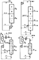
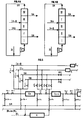
- FIG. 5 A common part of the device which is the subject of the present invention is shown diagrammatically in FIG. 5.
- This device comprises a certain number (favorably from 3 to 24) of chromatographic columns made up of sections or cylinders filled with a lining of a porous medium called stationary phase, which columns (C k ) whose walls are thermally insulated, are connected to each other in series and are percolated by an eluent (compressed gas, supercritical fluid or subcritical liquid) circulated by a compressor K or a pump with a mass flow carefully kept constant; the introductions of the mixture to be fractionated and of an eluent make-up as well as the withdrawals of a mixture called raffinate and of a mixture called extract are carried out between some of the columns (C k and C k + 1 ) as described above. has seen in Figure 1, all of these columns appearing separated for example into four areas.
- the method will be implemented in such a way that the eluting power of the elution fluid will be maintained substantially constant in each of these zones, but will be different from one zone to the other, with the fundamental difference of what is achieved in the processes described above using a liquid eluent.
- the implementation of the fractionation preferably requires the cadenced movement, at a fixed time interval ⁇ t, of the points of introduction of the eluent supply and of the mixture to be separated on the one hand, of the points of sampling of the raffinate and of the extract on the other hand, said points delimiting the four above-defined zones for passing from the intervals between the sections or columns (C k ) and (C k + 1 ) to the intervals between the sections or columns (C k + 1 ) and (C k + 2 ), which four zones will therefore move at the rate ⁇ t in the direction of the flow of the eluent (simulated counter-current) or in the opposite direction (simulated co-current).
- each column C k is connected to the next one C k + 1 via an all-or-nothing valve V k then a pressure regulating valve U k .
- the eluent at the outlet of the column C k and that coming from the recycling draw-off point SR possibly added with fresh eluent IE is recompressed in the compressor K or the pump via the on-off valves V ' k and V'' k respectively connected to the withdrawal line SR and to the recycling solvent injection line IR, the valves V k and U k then being closed.
- the extract sampling line SB is connected to a pressure regulating valve so as to regulate the pressure in the section of column C k , and is connected downstream of the valve U k and upstream of the column C k + 1 via a valve W k .
- This valve W k controlling the extraction of extract (SB) opens once per cycle. At this time, the valves V k and U k are open, the valves W 1 to W k-1 and W k + 1 to W n are closed, as well as the valves W ' k , W'' k and W ''' k .
- the raffinate sampling line SA is connected to a flow rate regulating valve so as to take a constant flow rate and is connected downstream of the valve U k and upstream of the column C k + 1 va a valve W ′ k .
- This valve W ' k controlling the withdrawal of raffinate SA opens once per cycle.
- the valves V k and U k are open while the valves W ' 1 to W' k-1 and W ' k + 1 to W' n are closed as well as the valves W k , W '' k and W ''' k .
- the lines IA + B and IE2 are each connected to a compressor or a separate pump, so as to deliver constant flow rates.
- Line IA + B is connected downstream of valve U k and upstream of column C k + 1 via a valve W ''' k .
- This valve controlling the mixture injection opens once per cycle. At this time the valves V k and U k are open, the valves W k , W ' k and W'' k are closed as well as the valves W''' 1 to W ''' k-1 and W''' k + 1 to W ''' n .
- valve W '' k controls the injection of solvent of lower density IE2 upstream of the column C k + 1 .
- This line is to be taken into account only when the injected mixture comprises three constituents ABC. In this case, a direct debit line for the SC extract must be added.
- the extraction points of the extract are distinct and are placed between C k and V k and are not represented in FIG. 5.
- the U valves marked open can be either totally open or partly open so as to regulate a difference in pressure between C k and C k + 1 .
- the feed of the mixture to be separated can be carried out either directly without prior dilution if the mixture is liquid at temperature and the supply pressure is more generally and more favorably after dilution of said mixture in the eluent itself previously carried or after this dilution under conditions similar to those desired by the operator in the zone considered (zone III according to the figure 1).
- This dilution operation is carried out conventionally according to the rules of the art: also by way of non-limiting example, this operation can be favorably carried out by dissolving the solid mixture to be fractionated within the percolating eluent on a bed of the solid, which eluent is then finding under conditions where its solvent power is fixed in such a way that it reaches the desired concentration in mixture by saturation: from even, if the mixture is liquid, we can favorably percolate the eluent as bubbles within the mixture under conditions where it is saturates the mixture, reaching the desired composition: if the mixture to fractionation is gaseous or liquid, we can also favorably achieve dissolution in the eluent by in-line mixing, the two flows being carefully regulated.
- the feed to be separated will preferably be gaseous or optionally liquid. We can then carry out the possible dissolution of the liquid charge in the gaseous eluent by example.
- This supply of the mixture to be separated is favorably carried out at a temperature and at a pressure very close to those fixed for the zone considered (zone III); the disturbances of the flow regime and of the chromatographic regime in the downstream columns are thus minimized.
- this feed can be used as an enthalpy supply to the system; in fact, the most favorable implementation of the process consists, as described above, in carrying out the isenthalpic variations in pressure through the control valves (denoted by (U k )): in certain cases, said expansion may s' accompanied by a significant drop in the temperature of the fluid which it is possible to compensate for by introducing the mixture to be fractionated at a temperature above said temperature of the fluid.
- the compression of the fluid within the compressor (K) is generally a source of heating of said fluid: it is possible to counterbalance this heating by introducing the additional eluent at a temperature lower than that of the fluid obtained from the last. upstream column.
- the raffinate and the extract withdrawn from the process itself are solutions of fractionated or separated products, within a certain quantity eluent.
- the application of the prior art as described for example in the aforementioned French patent FR-A-2584618 makes it possible to separate the eluent from the products, said eluent being able to be favorably recycled in the process via make-up by eluting: one of the important advantages of the process being of the invention lies precisely in the easy implementation of this operation, where, unlike the problems encountered when the eluent is a conventional liquid solvent, this separation does not require devices complex, nor of great energy consumption: moreover, when the eluent is, for example, pure carbon dioxide, fractionated products are not generally not polluted by any trace of residual organic solvent, which constitutes a considerable additional advantage.
- the pressure variations between the different zones can be low (pressure drops only) but preferably, at least one pressure modulation between two successive zones can be achieved by means of the pressure regulating valves U k of figure 5.
- FIG. 4A shows two improvements to the variant described in Figure 1, with the same references. Between zones I and II, is interposed a zone Z (FIG. 4A) defined upstream by the point of extraction of the extract and downstream via a point where part of the the extract substantially free of the eluent.
- zone Z defined upstream by the point of extraction of the extract and downstream via a point where part of the the extract substantially free of the eluent.
- the zone Z can be interposed between the zones III and IV and defined upstream by a reinjection point of part of the raffinate substantially free of the eluent and by the draw-off point of the raffinate downstream. This part of the raffinate can therefore be injected upstream of the zone Z.
- the pressure variations between the successive zones can be small (pressure losses only).
- at least two and at most four successive pressure levels can be created by means of at least one and at most three of the pressure regulation valves (U k-1 , U k , U k + 1 ) of Figure 5.
- At least two and at most five levels of separate pressure can be modulated in all zones, the pressure decreasing at least with each withdrawal and preferably at least two pressure levels other than those existing between zones 0 and I.
- at least one and at most four of the expansion valves connected on one side to the all-or-nothing valves and on the other to the columns k, k + 1, etc. are active and preferably at least one valve other than that existing between zones 0 and I.
- zone IV in figure 2 it is possible replace zone IV in figure 2 by allowing the mixture from the zone III in an expansion valve D, then possibly in a component refrigeration or reheating R and in a separator. The raffinate is then collected while the separated eluent is recycled by the compressor K to the injection pressure upstream of zone 0.
- This variant can be justified for the same reasons which were described during the description of the figure 3A.
- the variations in pressure levels between zones can be low (pressure drops only) but preferably the pressure can be modulated at the rate of at least one pressure interval between two successive withdrawals, the pressure decreasing at least with each withdrawal.
- the invention finds many applications in fractionations of mixtures and separations of components from, by example, from the chemical, food and pharmaceutical industries, as well than refining and petrochemicals.
- the device is made as described above in Figure 1 comprising twelve chromatographic columns or sections which are cylinders 30 cm long and 6 cm in diameter filled with a phase stationary consisting of particles of octadecyl grafted silica (RP 18) of a average diameter of the order of 35 ⁇ m, connected in series with the system of valves and compression described above.
- RP 18 octadecyl grafted silica
- the eluent consists of pure carbon dioxide. No heat exchanger is only installed in series between the columns.
- Several fractionation modes according to the process forming the subject of the invention have been implemented, according to the isobaric regime at substantially constant pressure in the 4 zones, close to 146 bars, temperature equal to 40 ° C on the one hand, according to the modulated elution power regime, in two different cases, on the other hand.
- the operating parameters and results of the fractionation obtained when the steady state is reached are presented below:
- Mass flow rate of the mixture to be separated 1.8 kg / h consisting of 0.100 kg / h of the mixture of naphthalene derivatives dissolved in 1.7 kg / h of carbon dioxide at 150 bar and 40 ° C.
- Mass flow rate for withdrawing the raffinate consisting of 0.050 kg / h naphthalene derivatives dissolved in 2.45 kg / h of carbon dioxide: 2.5 Kg / h.
- Mass flow rate of extraction of the extract consisting of 0.050 kg / h naphthalene derivatives dissolved in 2.55 kg / h of carbon dioxide: 2.6 kg / h.
- Mass flow rate leaving the compressor 37.2 kg / h.
- composition of the raffinate (after separation of CO 2 ): 88% of 2-methylnaphthalene.
- composition of the extract (after separation of CO 2 ): 89% in 1-methylnaphthalene.
- the pressure drop in the 12 columns or sections is very low making it possible to consider the regime at substantially constant pressure.
- the delay period is 10 minutes.
- Mass flow rate of the mixture to be separated 1.8 kg / h consisting of 0.100 kg / h of the mixture of naphthalene derivatives dissolved in 1.7 kg / h of pure carbon dioxide at 150 bar and 37 ° C.
- Mass flow rate for withdrawing the raffinate consisting of 0.050 kg / h naphthalene derivatives dissolved in 2.45 kg / h of carbon dioxide: 2.5 kg / h.
- Mass flow rate of extraction of the extract consisting of 0.050 kg / h naphthalene derivatives dissolved in 2.55 kg / h of carbon dioxide: 2.6 kg / h.
- Mass flow rate leaving the compressor 37.2 kg / h.
- composition of the raffinate (after separation of CO 2 ): 94.5% of 2-methylnaphthalene.
- composition of the extract (after separation of CO 2 ): 93.5% 1-methylnaphthalene.
- the pressure drop in the 12 columns or sections is also negligible, and in addition we can consider the regime as isothermal.
- the delay period is 10 minutes.
- Mass flow rate of the mixture to be separated 6 kg / h consisting of 0.100 kg / h of the mixture of naphthalene derivatives dissolved in 5.9 kg / h of pure carbon dioxide at 135 bar and 40 ° C.
- Mass flow rate for withdrawing the raffinate consisting of 0.050 kg / h naphthalene derivatives dissolved in 5.05 kg / h of carbon dioxide: 5.1 kg / h.
- Mass flow rate of extraction of the extract consisting of 0.050 kg / h naphthalene derivatives dissolved in 2.55 kg / h of carbon dioxide: 2.6 kg / h.
- Mass flow rate leaving the compressor 35 kg / h.
- composition of the raffinate (after separation of CO 2 ): 99.8% 2-methylnaphthalene.
- composition of the extract (after separation of CO2): 99.7% in 1-methylnaphthalene.
- the pressure drop in the 12 columns or sections is very low, and moreover we can consider the regime as isothermal.
- the period delay is 10 minutes.
- the method forming the subject of the invention has been implemented in fields where carbon dioxide is a so-called subcritical liquid under pressure substantially constant on the one hand, in power modulation regime elution on the other hand.
- the pressure drop in the 12 columns or sections is very weak.
- the delay period is 10 minutes.
- Example 2a we work with a liquid eluent subcritical, (pressure greater than critical pressure, temperature below at critical temperature).
- Example 2a is carried out under pressure practically constant and gives contents of 88 and 90%;
- example 2b with graduated pressures and pressure stages with number of columns or variable section from one zone to another (1-5-5-1) gives very high of 99.8 and 99.9%.
- Example 3 Separation of two isomers of pentane on a sieve molecular 5A illustrating the use of a compressed gaseous eluent according to the invention
- the densities of the adsorbed phase and the liquid phase are approximately equivalent: the separation which is carried out on 1 g of adsorbed material is found in part canceled by dilution with 3 g of unadsorbed material.
- the densities respective adsorbed and vapor phases are in a ratio of 20 to 500 depending on the pressure involved.
- zone I the internal flow rate is 78 t / h, at the entrance of this zone we 31 t / h of elution solvent is injected and 26.5 t / h of extract is collected at the outlet.
- the internal flow rate is 51.5 t / h.
- zone III the internal flow rate is 101.5 t / h; at the entrance of this zone, 50 t / h of feed is injected and 54.5 t / h of raffinate is collected at the exit.
- zone IV the internal flow rate is 47 t / h, this flow rate is recycled to the inlet of zone I by a pump.
- the total cycle time is 9 minutes.
- zone I the internal flow rate is 26 t / h; at the entrance to this area 24.5 t / h of elution solvent are injected and 23.5 t / h of extract is collected at its exit.
- the internal flow rate is 2.5 t / h.
- zone III the internal flow rate is 52.5 t / h; at the entrance of this 50 t / h of feed is injected into the zone and 51 t / h of raffinate is collected at the outlet.
- zone IV the internal flow is 1.5 t / h, this flow is recycled to the entry of zone I by a compressor.
- the compressibility coefficient of the eluent under these conditions is 0.94.
- Example 3b There are five beds of 3.75 m 3 each and the changeover period is set at 1 minutes 30 seconds, there are two beds in zone I, one bed in zone II, two beds in zone III; the total cycle time is 7 minutes 30 seconds.
- the installation is simplified and 17% of the operating sieve inventory is saved.
- zone I the pressure and the temperature are respectively 100 ° C and 46 bar, the internal flow rate is 31.5 t / h; at the entrance to this area we 24 t / h of solvent is injected and 23.5 t / h of extract is collected at its outlet.
- zone II the pressure and the temperature are respectively 100 ° C and 46 bar, the internal flow rate is 8 t / h.
- zone I and II the compressibility of ethane is 0.82.
- zone III the pressure and the temperature are respectively 90 ° C and 4.8 bar, the internal flow rate of 58 t / h; at the entrance to this area we inject 50 t / h of charge and at its outlet, 50.5 t / h of raffinate is collected.
- zone IV the pressure and the temperature are respectively 90 ° C and 4.8 bar, internal flow 7.5 t / h
- the compressibility coefficient of ethane under the conditions of zones III and IV is 0.98.
- zone IV to zone I does not take place at a constant flow rate at the outlet of zone IV since it is a column expansion of this zone. from 46 to 4.8 bar.
- zone II does not have a constant flow rate at its inlet since it must be repressurized from 4.8 bar to 46 bar.
- the isopentane purity and yield results are equivalent for the four examples 3a, 3b, 3c, 3d: purity of isopentane in the raffinate greater than 98%, isopentane yield in the raffinate greater than 98%.
- the devices and methods according to the invention allow therefore to achieve surprising results by the contents and yields with eluents at a pressure greater than or equal to the critical pressure and at higher or equal temperature (supercritical fluid), or lower (liquid subcritical) at the critical temperature, or even with gaseous eluents tablets, at a pressure lower than the critical pressure, and having a compressibility coefficient significantly different from 1, the temperature which may be either above or below the critical temperature.
- the mixture to be fractionated consists of 1 -methylnaphthalene (33% by mass), 2-methylnaphthalene (33% by mass) and compounds heavier assimilable to isomers of trimethylnaphthalene (33% in mass).
- the apparatus (figure 2), comprises fifteen columns or sections chromatography which are cylinders 30 cm long and 6 cm of diameter filled with a stationary phase consisting of particles of octadecyl grafted silica (RP 18) with an average diameter of the order of 35 micrometers, connected in series with the valve and compressor system described below.
- RP 18 octadecyl grafted silica
- the eluent consists of pure carbon dioxide. No heat exchanger is only arranged in series between the columns.
- Several modes of operation according to the method forming the subject of the invention have been implemented according to the two-state pressure regime described in patent FR-A-2651149, (zone 0 and zones I, II, III and IV) and according to the regime at pressure modulation described in the present invention on the other hand.
- the mixture to be fractionated consists of 2,5-bromothiophene (33% by mass), 3.4 dibromothiophene (33% by mass) and 2,3,4,5-tetrabromothiophene (33% by mass).
- the device is identical to the one used in the previous example and in Example 1 ( Figure 3).
- the eluent used is trifluorobromethane (CF 3 Br) whose critical coordinates are 39.7 bar and 67 ° C.
- CF 3 Br trifluorobromethane
- Several operating modes of the apparatus and according to the method forming the subject of the invention were implemented according to the regime at substantially constant pressure in the five zones close to 70 bar, (temperature equal to 80 ° C) d 'on the one hand, and on the other hand according to the pressure modulation regime described in the present application.
- zone 0 one: zone I: three: zone II: five: zone III: five: zone IV: one.
- the lag period is set at 3.3 minutes in all cases.
- FIG. 5 diagrammatically shows the assembly of two zones, columns or sections of columns C k and C k + 1 .
- valves with total opening / closing ( ⁇ all or nothing ⁇ ) V '' 'and the control valve U said valve U makes it possible to expand the fluid at the inlet pressure in zone I (line denoted IR2) and can advantageously be operated by regulating the flow in this branch of the circuit; said valves V '' 'are operated under the same conditions as the V'k valves. If the operator does not wish to use this recycling between zones (0 and I, figures 1 to 4), it can close both the U valve and all of the valves V '' ', all of the eluting fluid then being distributed by the line denoted IR1.
- the solvent is condensed in a heat exchanger heat and it is stored in an intermediate tank which makes it possible to obtain more regular pumping; the compressed fluid from the pump is then brought to working temperature thanks to a heat exchanger.
- the system is conventionally used in fluid extraction / fractionation supercritical and has not been shown in the figures.
Claims (16)
- Vorrichtung zur Fraktionierung eines Gemisches aus p Komponenten in p Komponenten oder q Schnitte, wobei q kleiner oder gleich p ist, die Vorrichtung eine Anordnung aus n chromatographischen Kolonnen oder chromatographischen Kolonnenabschnitten, die in Reihe und in geschlossener Schleife montiert sind, aufweist und wenigstens r Injektionsströme und höchstens n Injektionspunkte pro Injektionsstrom aufweist und q Abzugsströme und höchstens n Abzugspunkte pro Anzugsstrom besitzt, die Injektions- und Anzugspunkte der unterschiedlichen Ströme vorzugsweise zusammenfallen können, und wobei sich die Injektions- und Abzugsströme längs der Reihe von Kolonnen oder Kolonnenabschnitten abwechseln, wobei r, n, p und q wie folgt definierte ganze Zahlen sind:
- p :
- stellt die Anzahl der in der Charge p ≥ 2 vorhandenen Komponenten dar;
- q :
- stellt die Anzahl von Schnitten oder unterschiedlichen aus dem Verfahren stammenden Abströmen q ≥ 2 dar;
- n :
- gibt die Zahl unterschiedlicher Kolonnen oder unterschiedlicher Kolonnenabschnitte, die eingesetzt werden, wieder: n ≥ 3;
- r :
- gibt die Anzahl der unterschiedlichen Injektionsströme
in der Vorrichtung und bevorzugt q ≥ r ≥ 2 wieder;
wobei die Schleife gebildet ist aus m aufeinanderfolgenden chromatographischen Zonen derart, daß (I, II, III; I, II, III, IV; 0, I, II, III, IV; I, Z, II, III, IV; I, II, III, Z, IV), von denen jede dieser Zonen gebildet ist durch wenigstens eine Kolonne oder einen Kolonnenabschnitt (Ck); - m :
- gibt die Anzahl der Zonen:
- Vorrichtung nach Anspruch 1, drei aufeinanderfolgende Zonen I, II, III umfassend, die für die Trennung von zwei Komponenten oder zwei Schnitten ausgelegt sind, wobei der Zone III (vor der das Gemisch A+B eingeführt wird), unmittelbar ein Entspannungs und Trennorgan für das Eluierungsmittel und das Raffinat folgt, wobei das Entspannungs- und Trennorgan den Abzugspunkt für das Raffinat und den Abzugspunkt für die Recyclierung des Eluierungsmittels (SR) umfaßt, der mit dem Kompressor oder der Pumpe verbunden ist, was es ermöglicht, die Zone IV in Fortfall kommen zu lassen.
- Vorrichtung nach einem der Ansprüche 1 bis 2, bei der man zwischen die Zonen I und II eine Zone Z zwischenschaltet, die vor dem Abzugspunkt des Extraktes (SB) und in Strömungsrichtung dahinter durch einen Reinjektionspunkt (IRB) eines Teils des vom Eluierungsmittel im wesentlichen befreiten Extraktes definiert ist.
- Vorrichtung nach einem der Ansprüche 1 bis 2, bei der man hinter der Zone III eine Zone Z zwischenschaltet, die anströmseitig definiert ist durch einen Reinjektionspunkt (IRA) eines Teils des vom Eluierungsmittel im wesentlichen befreiten Raffinats und abströmseitig definiert ist durch den Abzugspunkt für das Raffinat (SA).
- Vorrichtung nach Anspruch 1, bei der, wenn vier Zonen (0, I, II, III) oder fünf Zonen (0, I, II, III, IV) vorhanden sind, wenigstens ein Organ zur Reduktion des Druckes oder zur zusätzlichen Entspannung, verbunden mit der Zeitverschiebungssteuervorrichtung, sich zwischen der Zone 0 und der Zone 1 befindet.
- Vorrichtung nach einem der Ansprüche 1 und 5, vier aufeinanderfolgende Zonen 0, I, II, III umfassend zur Trennung der drei Komponenten A, B, C oder drei Schnitte umfassend, bei der der Zone III (die abströmseitig zum Injektionspunkt des Gemisches
- Verfahren zum Fraktionieren eines Gemisches aus p Komponenten in p Komponenten oder q Schnitte, wobei q kleiner oder gleich p ist, in einer Vorrichtung, die eine Anordnung von n chromatographischen Kolonnen oder chromatographischen Kolonnenabschnitten aufweist, die in Reihe und in geschlossener Schleife geschaltet sind und wenigstens r Injektionsströme und höchstens n Injektionspunkte pro Injektionsstrom aufweisen und über q Abzugsströme und höchstens n Abzugspunkte pro Abzugsstrom verfügen, wobei die Injektions- und Abzugspunkte der unterschiedlichen Ströme vorzugsweise zusammenfallen können, die Injektions- und Abzugsströme sich längs der Reihe von Kolonnen oder Abschnitten abwechseln, wobei r, n, p und q ganze Zahlen der folgenden Definition sind:
- p :
- steht für die Anzahl von in der Charge vorhandenen Komponenten p ≥ 2;
- q :
- steht für die Anzahl von unterschiedlichen Schnitten oder Abströmen, die aus dem Verfahren stammen q ≥ 2;
- n :
- steht für die Anzahl unterschiedlicher Kolonnen oder unterschiedlicher Kolonnenabschnitte die eingesetzt werden: n ≥ 3;
- r :
- steht für die Anzahl von unterschiedlichen Injektionsströmen
in der Vorrichtung und bevorzugt q ≥ r ≥ 2;
wobei die Schleife gebildet wird aus m aufeinanderfolgenden chromatographischen Zonen, derart (I, II, III; I, II, III, IV; 0, I, II, III, IV; I, Z, II, III, IV; I, II, III, Z, IV), wobei jede dieser Zonen gebildet wird durch wenigstens eine Kolonne oder einen Abschnitt (Ck); - m :
- steht für die Anzahl von Zonen:
entweder (1) mit Injektion als Eluierungsmittel eines komprimierten Gases, dessen Druck an jeder Stelle der Zonen kleiner als der kritische Druck des Gases ist, wobei das Gas einen Kompressibilitätskoeffizienten, im wesentlichen unterschiedlich zu 1 an jedem Punkt wenigstens einer Zone und bevorzugt an jedem Punkt von wenigstens zwei Zonen ausgehend vom Injektionspunkt des Eluierungsmittels aufweist;oder (2) mit Injektion als Eluierungsmittel wenigstens eines superkritischen Fluids;oder (3) mit Injektion als Eluierungsmittel wenigstens einer unterkritischen Flüssigkeit, wobei das Verfahren im übrigen derart durchgeführt wird, daß zur Trennung eines Gemisches in zwei Komponenten oder zwei Schnitte man den Druck in einer Kolonne (oder einer Zone) größer als den in der Kolonne (oder der Zone), die unmittelbar strömungsabwärts folgt, bis auf jeden Eluierungsmittelinjektionspunkt hält, wo der Druck bis zum Injektionsdruck steigt; und daß im Hinblick auf die Trennung eines Gemisches in drei Komponenten oder drei Schnitte man den Druck um wenigstens ein Intervall zwischen zwei Abzugspunkten außer dem Extraktabzugspunkt zwischen den Zonen 0 und I abnehmen läßt. - Vorrichtung nach Anspruch 7, bei dem man den Druck um wenigstens ein Intervall zwischen zwei Abzugspunkten von der anströmseitigen Injektion des Abströmmittels (IR1) bis zum Recyclierungsabzugspunkt (SR) abnehmen läßt.
- Verfahren nach einem der Ansprüche 7 und 8, bei dem das Eluierungsfluid in die Schleife bei einer Temperatur unterschiedlich zur Arbeitstemperatur injiziert wird.
- Verfahren nach einem der Ansprüche 7 bis 9, bei dem man im übrigen den Druck zwischen der Zone 0 und der Zone I im Hinblick auf die Trennung eines Gemisches in drei Komponenten oder drei Schnitte abnehmen läßt.
- Verfahren nach einem der Ansprüche 7 bis 10, bei dem man ein Gemisch aus drei Komponenten in eine Vorrichtung injiziert, die über vier Zonen (0, I, II, III) verfügt, bei dem man die Gesamtheit des Eluierungsmittels und des Raffinats hinter der Zone III entspannt, vor der die Charge (
- Verfahren nach einem der Ansprüche 7 und 9, bei dem man ein Gemisch aus zwei Komponenten in eine Vorrichtung injiziert, die drei Zonen (I, II, III) umfaßt, bei dem man entspannt und trennt die Gesamtheit des Eluierungsmittels und des Raffinats abströmseitig zur Zone III, wo das Gemisch (AB) injiziert worden war, man das Raffinat sammelt und den Recyclierungsstrom des Eluierungsmittels bei Injektionsdruck recycliert.
- Verfahren nach einem der Ansprüche 7, 9 und 12, bei dem man einen Teil des im wesentlichen vom Eluierungsmittel hinter einer Zone zwischen der Zone I und II befreiten Extraktes, definiert vor dem Abzugspunkt des Extraktes (SB) und in Abströmrichtung durch einen Reinjektionspunkt (IRB) für diesen Teil des vom Eluierungsmittel im wesentlichen befreiten Extraktes einführt.
- Verfahren nach einem der Ansprüche 7, 9 und 12, bei dem man einen Teil des im wesentlichen vom Eluierungsmittel befreiten Raffinats vor einer Zone Z einführt, die hinter der Zone III angeordnet ist und anströmseitig durch einen Punkt (IRA) der Reinjektion dieses Teiles des Raffinats, der im wesentlichen vom Eluierungsmittel befreit wurde und abströmseitig durch einen Abzugspunkt des Raffinats (SA) definiert ist.
- Verfahren nach einem der Ansprüche 7 bis 14, bei dem der Druck in der Zone III um wenigstens 1 bar und bevorzugt 3 bis 100 bar kleiner als der Druck in der Zone II ist.
- Verfahren nach einem der Ansprüche 7 bis 15, bei dem der Druck zwischen jeder Zone ausgehend von der das Eluierungsmittel aufnehmenden Zone abnimmt.
Applications Claiming Priority (7)
| Application Number | Priority Date | Filing Date | Title |
|---|---|---|---|
| FR9205304A FR2690630B1 (fr) | 1992-04-29 | 1992-04-29 | Procede et dispositif de fractionnement de melanges de composants par voie chromatographique a l'aide d'un eluant a pression supercritique. |
| FR9205304 | 1992-04-29 | ||
| FR9209444A FR2694208B1 (fr) | 1992-07-30 | 1992-07-30 | Procédé et dispositif industriels de fractionnement de mélanges de composants par chromatographie. |
| FR9209444 | 1992-07-30 | ||
| FR9304703 | 1993-04-21 | ||
| FR9304703A FR2704158B3 (fr) | 1993-04-21 | 1993-04-21 | Procédé et dispositif de fractionnement d'un mélange en lit mobile simulé en présence d'un gaz comprimé. |
| PCT/FR1993/000419 WO1993022022A1 (fr) | 1992-04-29 | 1993-04-28 | Procede et dispositif de fractionnement d'un melange en lit mobile simule en presence d'un gaz comprime, d'un fluide supercritique ou d'un liquide subcritique |
Publications (2)
| Publication Number | Publication Date |
|---|---|
| EP0592646A1 EP0592646A1 (de) | 1994-04-20 |
| EP0592646B1 true EP0592646B1 (de) | 1999-02-03 |
Family
ID=27252600
Family Applications (1)
| Application Number | Title | Priority Date | Filing Date |
|---|---|---|---|
| EP93910080A Expired - Lifetime EP0592646B1 (de) | 1992-04-29 | 1993-04-28 | Verfahren und vorrichtung zur chromatographischen fraktionierung einer mischung mittels eines simulierten fliessbetts in gegenwart eines komprimierten gases, eines überkritischem fluides oder einer unterkritischen flüssigkeit |
Country Status (9)
| Country | Link |
|---|---|
| US (1) | US5422007A (de) |
| EP (1) | EP0592646B1 (de) |
| JP (1) | JPH07500771A (de) |
| CA (1) | CA2111084C (de) |
| DE (1) | DE69323382T2 (de) |
| DK (1) | DK0592646T3 (de) |
| ES (1) | ES2130262T3 (de) |
| NO (1) | NO303485B1 (de) |
| WO (1) | WO1993022022A1 (de) |
Families Citing this family (42)
| Publication number | Priority date | Publication date | Assignee | Title |
|---|---|---|---|---|
| US5770088A (en) * | 1992-06-30 | 1998-06-23 | Daicel Chemical Industries, Ltd. | Simulated moving bed chromatographic separation process |
| US5719302A (en) * | 1993-04-29 | 1998-02-17 | Pronova A.S | Processes for chromatographic fractionation of fatty acids and their derivatives |
| FR2719233B1 (fr) * | 1994-04-28 | 1996-07-19 | Inst Francais Du Petrole | Procédé de séparation en lit mobile simulé à débit de recyclage constant. |
| EP0687491A1 (de) * | 1994-06-16 | 1995-12-20 | Daicel Chemical Industries, Ltd. | Chromatographisches simuliertes Wanderbetttrennungsverfahren |
| CN1116088C (zh) * | 1994-06-17 | 2003-07-30 | 代科化学工业株式会社 | 模拟移动床色谱分离方法 |
| FR2721528B1 (fr) * | 1994-06-22 | 1996-09-06 | Inst Francais Du Petrole | Procédé de séparation par chromatographie en lit mobile simulé avec correction de volume mort par desynchronisation des périodes. |
| FR2721529B1 (fr) | 1994-06-22 | 1996-09-06 | Inst Francais Du Petrole | Procédé de séparation par chromatographie en lit mobile simulé avec correction de volume mort par diminution de longueur. |
| FR2721527B1 (fr) * | 1994-06-22 | 1996-09-06 | Inst Francais Du Petrole | Procédé de séparation par chromatographie en lit mobile simulé avec correction de volume mort par augmentation de débit. |
| US5635072A (en) * | 1995-01-31 | 1997-06-03 | Uop | Simulated moving bed adsorptive separation process |
| FR2743002B1 (fr) * | 1995-12-27 | 1998-01-30 | Inst Francais Du Petrole | Procede de regulation d'au moins un debit de fluide circulant dans une boucle de separation chromatographique en lit mobile simule |
| FR2751888B1 (fr) * | 1996-07-31 | 1998-09-11 | Inst Francais Du Petrole | Dispositif et procede de rincage en lit mobile simule comportant au moins deux lignes de distribution de fluides |
| JP3443426B2 (ja) * | 1997-01-07 | 2003-09-02 | アマルガメイテッド リサーチ インコーポレイテッド | 疑似移動層ブロック分離法 |
| FR2766385B1 (fr) * | 1997-07-24 | 1999-09-03 | Novasep | Procede pour le controle de la pression dans un systeme de separation a lit mobile simule |
| FR2772634B1 (fr) * | 1997-12-22 | 2000-02-18 | Inst Francais Du Petrole | Procede et dispositif d'amelioration de la purete d'un produit en lit mobile simule |
| FR2781860B1 (fr) * | 1998-07-31 | 2000-09-01 | Inst Francais Du Petrole | Systeme de mise en communication alternee d'au moins quatre fluides et son application dans un procede de separation en lit mobile simule |
| FR2790479B1 (fr) * | 1999-03-02 | 2001-04-13 | Commissariat Energie Atomique | Procede de traitement d'une huile utilisant un fluide a l'etat supercritique |
| DE19934168A1 (de) * | 1999-07-21 | 2001-01-25 | K D Pharma Bexbach Gmbh | Säulenchromatographisches Trennverfahren im Rahmen einer Flüssigkeitschromatographie mittels niedermolekularen Eluenten |
| FR2803538B1 (fr) * | 1999-12-15 | 2002-06-07 | Separex Sa | Procede et dispositif de captage de fines particules par percolation dans un lit de granules |
| DE10051427C1 (de) | 2000-10-17 | 2002-06-13 | Adam Mueller | Verfahren zur Herstellung eines Tetrahydrocannabinol- und Cannabidiol-haltigen Extraktes aus Cannabis-Pflanzenmaterial sowie Cannabis-Extrakte |
| DE10235385B4 (de) * | 2002-08-02 | 2006-10-05 | MAX-PLANCK-Gesellschaft zur Förderung der Wissenschaften e.V. | Verfahren zur chromatographischen Trennung von Komponenten |
| FR2846252B1 (fr) * | 2002-10-29 | 2005-07-01 | Novasep | Procede et dispositif de chromatographie integrant une etape de concentration |
| FR2856313B1 (fr) * | 2003-06-17 | 2005-07-29 | Inst Francais Du Petrole | Methode de gestion des vannes d'un systeme de separation a lit mobile simule |
| DE102004000042B4 (de) | 2004-11-16 | 2006-09-14 | Joint Analytical Systems Gmbh | Vorrichtung und Verfahren zum Bestimmen von Stoffeigenschaften mittels HPLC |
| US20070051130A1 (en) * | 2005-09-06 | 2007-03-08 | Ming-Chi Chung | Supercritical fractionating apparatus and process |
| JP4940756B2 (ja) * | 2006-05-22 | 2012-05-30 | ソニー株式会社 | マイクロ流路系 |
| WO2008025887A1 (fr) * | 2006-08-28 | 2008-03-06 | Novasep | Procede d'enrichissement d'un ou plusieurs composes d'un melange utilisant une phase mobile liquide contenant un gaz |
| JP5872483B2 (ja) | 2009-12-30 | 2016-03-01 | ビーエイエスエフ ファーマ(コーラニッシュ)リミテッド | 擬似移動床式クロマトグラフ分離方法 |
| US8293111B2 (en) * | 2010-05-17 | 2012-10-23 | Uti Limited Partnership | Apparatus, system, and method for chromatography using a water stationary phase |
| GB201111595D0 (en) | 2011-07-06 | 2011-08-24 | Equateq Ltd | Improved process |
| GB201111591D0 (en) | 2011-07-06 | 2011-08-24 | Equateq Ltd | Further new process |
| GB201111594D0 (en) | 2011-07-06 | 2011-08-24 | Equateq Ltd | New improved process |
| GB201111589D0 (en) | 2011-07-06 | 2011-08-24 | Equateq Ltd | New modified process |
| GB201111601D0 (en) | 2011-07-06 | 2011-08-24 | Equateq Ltd | New process |
| GB201300354D0 (en) | 2013-01-09 | 2013-02-20 | Basf Pharma Callanish Ltd | Multi-step separation process |
| US9428711B2 (en) | 2013-05-07 | 2016-08-30 | Groupe Novasep | Chromatographic process for the production of highly purified polyunsaturated fatty acids |
| US8802880B1 (en) | 2013-05-07 | 2014-08-12 | Group Novasep | Chromatographic process for the production of highly purified polyunsaturated fatty acids |
| WO2014201222A1 (en) | 2013-06-14 | 2014-12-18 | Waters Technologies Corporation | Methodology for scaling methods between supercritical fluid chromatography systems |
| EP3118186B1 (de) | 2013-12-11 | 2022-02-09 | Novasep Process | Chromatografische anlage zur herstellung von mehrfach ungesättigten fettsäuren |
| EP3092218B1 (de) | 2014-01-07 | 2022-03-09 | Novasep Process Solutions | Verfahren zur reinigung von aminosäuren |
| US20170080357A1 (en) * | 2014-05-12 | 2017-03-23 | Waters Technologies Corporation | Column temperature compensation for carbon dioxide based chromatographic system |
| US10913906B2 (en) * | 2015-12-14 | 2021-02-09 | Sabic Global Technologies B.V. | Process for separation of aromatic hydrocarbons from a mixed hydrocarbon stream |
| WO2018073500A1 (fr) * | 2016-10-21 | 2018-04-26 | Novasep Process | Utilisation de gaz comprimé pour le déplacement d'éluant appliqué à la chromatographie |
Family Cites Families (16)
| Publication number | Priority date | Publication date | Assignee | Title |
|---|---|---|---|---|
| US3761533A (en) * | 1970-07-23 | 1973-09-25 | Toray Industries | Separation process of components of feed mixture utilizing solid sorbent |
| US4500432A (en) * | 1981-07-13 | 1985-02-19 | Hewlett-Packard Company | Automated sample concentrator for trace components |
| FR2527934A1 (fr) * | 1982-06-03 | 1983-12-09 | Elf Aquitaine | Procede de fractionnement de melanges par chromatographie d'elution avec fluide en etat supercritique et installation pour sa mise en oeuvre |
| US4402832A (en) * | 1982-08-12 | 1983-09-06 | Uop Inc. | High efficiency continuous separation process |
| DE3461421D1 (en) * | 1983-06-03 | 1987-01-15 | Hewlett Packard Co | Chromatographic separation |
| US4498991A (en) * | 1984-06-18 | 1985-02-12 | Uop Inc. | Serial flow continuous separation process |
| US5122275A (en) * | 1986-05-08 | 1992-06-16 | A. E. Staley Manufacturing Company | Simulated moving bed chromatographic separation |
| JPH0669521B2 (ja) * | 1986-12-23 | 1994-09-07 | 三菱化成エンジニアリング株式会社 | クロマト分離法 |
| US5180487A (en) * | 1987-09-25 | 1993-01-19 | Nihon Bunko Kogyo Kabushiki Kaisha | Pump apparatus for transferring a liquified gas used in a recycle chromatograph |
| JPH0746097B2 (ja) * | 1988-05-17 | 1995-05-17 | 三菱化成エンジニアリング株式会社 | クロマト分離法 |
| US4990259A (en) * | 1988-12-16 | 1991-02-05 | The Amalgamated Sugar Company | Chromatographic separator sorbent bed preparation |
| US5102553A (en) * | 1988-12-16 | 1992-04-07 | The Amalgamated Sugar Company | Time variable simulated moving bed process |
| FR2651148B1 (fr) * | 1989-08-28 | 1992-05-07 | Inst Francais Du Petrole | Procede continu et dispositif de separation chromatographique d'un melange d'au moins trois constituants en trois effluents purifies au moyen de deux solvants. |
| FR2651149B1 (fr) * | 1989-08-28 | 1992-06-05 | Inst Francais Du Petrole | Procede continu et dispositif de separation chromatographique d'un melange d'au moins trois constituants en trois effluents purifies au moyen d'un seul solvant a deux temperatures et/ou a deux pressions differentes. |
| US5198120A (en) * | 1989-12-26 | 1993-03-30 | Japan Organo Co., Ltd. | Process for fractional separation of multi-component fluid mixture |
| US5156736A (en) * | 1991-05-07 | 1992-10-20 | Schoenrock Karlheinz W R | Simulated moving bed apparatus using a single sorbent bed for separating components from a fluid stream |
-
1993
- 1993-04-28 DK DK93910080T patent/DK0592646T3/da active
- 1993-04-28 ES ES93910080T patent/ES2130262T3/es not_active Expired - Lifetime
- 1993-04-28 WO PCT/FR1993/000419 patent/WO1993022022A1/fr active IP Right Grant
- 1993-04-28 US US08/170,248 patent/US5422007A/en not_active Expired - Lifetime
- 1993-04-28 JP JP5519004A patent/JPH07500771A/ja active Pending
- 1993-04-28 EP EP93910080A patent/EP0592646B1/de not_active Expired - Lifetime
- 1993-04-28 CA CA002111084A patent/CA2111084C/fr not_active Expired - Lifetime
- 1993-04-28 DE DE69323382T patent/DE69323382T2/de not_active Expired - Lifetime
- 1993-12-27 NO NO934830A patent/NO303485B1/no not_active IP Right Cessation
Also Published As
| Publication number | Publication date |
|---|---|
| NO934830D0 (no) | 1993-12-27 |
| WO1993022022A1 (fr) | 1993-11-11 |
| CA2111084C (fr) | 2004-07-06 |
| NO934830L (no) | 1994-02-25 |
| JPH07500771A (ja) | 1995-01-26 |
| US5422007A (en) | 1995-06-06 |
| NO303485B1 (no) | 1998-07-20 |
| EP0592646A1 (de) | 1994-04-20 |
| DK0592646T3 (da) | 1999-09-20 |
| DE69323382D1 (de) | 1999-03-18 |
| ES2130262T3 (es) | 1999-07-01 |
| CA2111084A1 (fr) | 1993-11-11 |
| DE69323382T2 (de) | 1999-06-10 |
Similar Documents
| Publication | Publication Date | Title |
|---|---|---|
| EP0592646B1 (de) | Verfahren und vorrichtung zur chromatographischen fraktionierung einer mischung mittels eines simulierten fliessbetts in gegenwart eines komprimierten gases, eines überkritischem fluides oder einer unterkritischen flüssigkeit | |
| EP0099765B1 (de) | Verfahren zum Fraktionieren von Gemischen durch Elutionschromatographie mit einer überkritischen fluiden Phase und Anlage zur Durchführung dieses Verfahrens | |
| EP0415822B1 (de) | Kontinuierliches Verfahren und Vorrichtung für eine chromatographische Trennung einer Mischung von mindestens drei Bestandteilen in drei gereinigte Ausflüsse mittels eines Lösungsmittels bei zwei verschiedenen Temperaturen und/oder Drucken | |
| EP1912716B1 (de) | Verfahren und vorrichtung zur trennung von fraktionen einer mischung | |
| CA2348719C (fr) | Procede et dispositif de separation avec des zones chromatographiques a longueur variable | |
| FI81268C (fi) | Kontinuerligt separationsfoerfarande baserat pao seriestroemning. | |
| EP2276548B1 (de) | Gradientenelutionsmehrsäulentrennverfahren | |
| NO162701B (no) | Fremgangsmaate for aa skille en ekstraktkomponent fra en raffinatkomponent inneholdt i en tilfoerselsblanding. | |
| FR2651148A1 (fr) | Procede continu et dispositif de separation chromatographique d'un melange d'au moins trois constituants en trois effluents purifies au moyen de deux solvants. | |
| WO1996018445A1 (fr) | Procede et installation de separation de composes lourds et legers, par extraction par un fluide supercritique et nanofiltration | |
| FR2935100A1 (fr) | Procede et dispositif de separation en lit mobile simule a debit de fluide de derivation module | |
| FR2721529A1 (fr) | Procédé de séparation par chromatographie en lit mobile simulé avec correction de volume mort par diminution de longueur. | |
| EP0688589A1 (de) | Trennverfahren mittels simulierter Wanderbettchromatographie mit Korrektur des Totvolumens durch Desynchronisation der Perioden | |
| FR2808270A1 (fr) | Procede de coproduction de metaxylene et de paraxylene | |
| FR2460703A1 (fr) | Procede de separation ou de purification de melanges a l'aide d'un solide adsorbant | |
| FR2721527A1 (fr) | Procédé de séparation par chromatographie en lit mobile simulé avec correction de volume mort par augmentation de débit. | |
| FR2690630A1 (fr) | Procédé et dispositif de fractionnement de mélanges de composants par voie chromatographique à l'aide d'un éluant à pression supercritique. | |
| EP0254610B1 (de) | Verfahren zum Trennen von Stoffgemischen mit einem überkritischen Fluidum | |
| FR2704158A1 (fr) | Procédé et dispositif de fractionnement d'un mélange en lit mobile simulé en présence d'un gaz comprimé. | |
| FR2694208A1 (fr) | Procédé et dispositif industriels de fractionnement de mélanges de composants par chromatographie. | |
| FR2997396A1 (fr) | Procede et dispositif de production de paraxylene en contre-courant simule constitue de deux adsorbeurs en serie a nombre total de lits inferieur ou egal a 22 | |
| CA3119417A1 (fr) | Procede et dispositif de transfert de matiere en continu a contre-courant entre deux phases fluides | |
| FR2794379A1 (fr) | Dispositif de fractionnement de melanges a membrane operant a pression supercritique | |
| CA3039158C (fr) | Utilisation de gaz comprime pour le deplacement d'eluant applique a la chromatographie | |
| EP3583988A1 (de) | Abscheideverfahren und -vorrichtung im simulierten fliessbett mit einer geringen anzahl von fliessbetten mit ablenkungsflüssigkeitsdurchsatz |
Legal Events
| Date | Code | Title | Description |
|---|---|---|---|
| PUAI | Public reference made under article 153(3) epc to a published international application that has entered the european phase |
Free format text: ORIGINAL CODE: 0009012 |
|
| 17P | Request for examination filed |
Effective date: 19931214 |
|
| AK | Designated contracting states |
Kind code of ref document: A1 Designated state(s): BE CH DE DK ES FR GB IT LI NL SE |
|
| 17Q | First examination report despatched |
Effective date: 19951018 |
|
| GRAG | Despatch of communication of intention to grant |
Free format text: ORIGINAL CODE: EPIDOS AGRA |
|
| GRAG | Despatch of communication of intention to grant |
Free format text: ORIGINAL CODE: EPIDOS AGRA |
|
| GRAH | Despatch of communication of intention to grant a patent |
Free format text: ORIGINAL CODE: EPIDOS IGRA |
|
| GRAH | Despatch of communication of intention to grant a patent |
Free format text: ORIGINAL CODE: EPIDOS IGRA |
|
| GRAH | Despatch of communication of intention to grant a patent |
Free format text: ORIGINAL CODE: EPIDOS IGRA |
|
| GRAA | (expected) grant |
Free format text: ORIGINAL CODE: 0009210 |
|
| AK | Designated contracting states |
Kind code of ref document: B1 Designated state(s): BE CH DE DK ES FR GB IT LI NL SE |
|
| ITF | It: translation for a ep patent filed |
Owner name: DE DOMINICIS & MAYER S.R.L. |
|
| REG | Reference to a national code |
Ref country code: CH Ref legal event code: EP |
|
| GBT | Gb: translation of ep patent filed (gb section 77(6)(a)/1977) |
Effective date: 19990211 |
|
| REF | Corresponds to: |
Ref document number: 69323382 Country of ref document: DE Date of ref document: 19990318 |
|
| REG | Reference to a national code |
Ref country code: ES Ref legal event code: FG2A Ref document number: 2130262 Country of ref document: ES Kind code of ref document: T3 |
|
| REG | Reference to a national code |
Ref country code: DK Ref legal event code: T3 |
|
| PLBE | No opposition filed within time limit |
Free format text: ORIGINAL CODE: 0009261 |
|
| STAA | Information on the status of an ep patent application or granted ep patent |
Free format text: STATUS: NO OPPOSITION FILED WITHIN TIME LIMIT |
|
| 26N | No opposition filed | ||
| REG | Reference to a national code |
Ref country code: GB Ref legal event code: IF02 |
|
| REG | Reference to a national code |
Ref country code: FR Ref legal event code: CD |
|
| REG | Reference to a national code |
Ref country code: DE Ref legal event code: R081 Ref document number: 69323382 Country of ref document: DE Owner name: SEPAREX S.A., FR Free format text: FORMER OWNERS: INSTITUT FRANCAIS DU PETROLE, RUEIL-MALMAISON, HAUTS-DE-SEINE, FR; SEPAREX S.A., CHAMPIGNEULLES, FR Effective date: 20110329 Ref country code: DE Ref legal event code: R081 Ref document number: 69323382 Country of ref document: DE Owner name: IFP ENERGIES NOUVELLES, FR Free format text: FORMER OWNERS: INSTITUT FRANCAIS DU PETROLE, RUEIL-MALMAISON, HAUTS-DE-SEINE, FR; SEPAREX S.A., CHAMPIGNEULLES, FR Effective date: 20110329 Ref country code: DE Ref legal event code: R081 Ref document number: 69323382 Country of ref document: DE Owner name: SEPAREX S.A., FR Free format text: FORMER OWNER: INSTITUT FRANCAIS DU PETROLE, SEPAREX S.A., , FR Effective date: 20110329 Ref country code: DE Ref legal event code: R081 Ref document number: 69323382 Country of ref document: DE Owner name: IFP ENERGIES NOUVELLES, FR Free format text: FORMER OWNER: INSTITUT FRANCAIS DU PETROLE, SEPAREX S.A., , FR Effective date: 20110329 |
|
| PGFP | Annual fee paid to national office [announced via postgrant information from national office to epo] |
Ref country code: BE Payment date: 20120430 Year of fee payment: 20 Ref country code: DK Payment date: 20120425 Year of fee payment: 20 Ref country code: CH Payment date: 20120426 Year of fee payment: 20 Ref country code: DE Payment date: 20120509 Year of fee payment: 20 Ref country code: NL Payment date: 20120514 Year of fee payment: 20 |
|
| PGFP | Annual fee paid to national office [announced via postgrant information from national office to epo] |
Ref country code: SE Payment date: 20120425 Year of fee payment: 20 Ref country code: GB Payment date: 20120425 Year of fee payment: 20 Ref country code: FR Payment date: 20120423 Year of fee payment: 20 |
|
| PGFP | Annual fee paid to national office [announced via postgrant information from national office to epo] |
Ref country code: IT Payment date: 20120421 Year of fee payment: 20 |
|
| PGFP | Annual fee paid to national office [announced via postgrant information from national office to epo] |
Ref country code: ES Payment date: 20120420 Year of fee payment: 20 |
|
| REG | Reference to a national code |
Ref country code: DE Ref legal event code: R071 Ref document number: 69323382 Country of ref document: DE |
|
| REG | Reference to a national code |
Ref country code: DK Ref legal event code: EUP |
|
| BE20 | Be: patent expired |
Owner name: INSTITUT FRANCAIS DU *PETROLE Effective date: 20130428 Owner name: SOC. *SEPAREX Effective date: 20130428 |
|
| REG | Reference to a national code |
Ref country code: DE Ref legal event code: R071 Ref document number: 69323382 Country of ref document: DE Ref country code: CH Ref legal event code: PL |
|
| REG | Reference to a national code |
Ref country code: NL Ref legal event code: V4 Effective date: 20130428 |
|
| REG | Reference to a national code |
Ref country code: GB Ref legal event code: PE20 Expiry date: 20130427 |
|
| REG | Reference to a national code |
Ref country code: ES Ref legal event code: FD2A Effective date: 20130722 |
|
| PG25 | Lapsed in a contracting state [announced via postgrant information from national office to epo] |
Ref country code: GB Free format text: LAPSE BECAUSE OF EXPIRATION OF PROTECTION Effective date: 20130427 Ref country code: DE Free format text: LAPSE BECAUSE OF EXPIRATION OF PROTECTION Effective date: 20130430 |