EP0592646B1 - Method and device for chromatographically fractionating a mixture in a simulated mobile bed in the presence of a compressed gas, a supercritical fluid or a subcritical liquid - Google Patents
Method and device for chromatographically fractionating a mixture in a simulated mobile bed in the presence of a compressed gas, a supercritical fluid or a subcritical liquid Download PDFInfo
- Publication number
- EP0592646B1 EP0592646B1 EP93910080A EP93910080A EP0592646B1 EP 0592646 B1 EP0592646 B1 EP 0592646B1 EP 93910080 A EP93910080 A EP 93910080A EP 93910080 A EP93910080 A EP 93910080A EP 0592646 B1 EP0592646 B1 EP 0592646B1
- Authority
- EP
- European Patent Office
- Prior art keywords
- zone
- eluent
- injection
- point
- pressure
- Prior art date
- Legal status (The legal status is an assumption and is not a legal conclusion. Google has not performed a legal analysis and makes no representation as to the accuracy of the status listed.)
- Expired - Lifetime
Links
Images
Classifications
-
- B—PERFORMING OPERATIONS; TRANSPORTING
- B01—PHYSICAL OR CHEMICAL PROCESSES OR APPARATUS IN GENERAL
- B01D—SEPARATION
- B01D15/00—Separating processes involving the treatment of liquids with solid sorbents; Apparatus therefor
- B01D15/08—Selective adsorption, e.g. chromatography
- B01D15/10—Selective adsorption, e.g. chromatography characterised by constructional or operational features
- B01D15/18—Selective adsorption, e.g. chromatography characterised by constructional or operational features relating to flow patterns
- B01D15/1814—Selective adsorption, e.g. chromatography characterised by constructional or operational features relating to flow patterns recycling of the fraction to be distributed
- B01D15/1821—Simulated moving beds
- B01D15/1842—Simulated moving beds characterized by apparatus features
-
- B—PERFORMING OPERATIONS; TRANSPORTING
- B01—PHYSICAL OR CHEMICAL PROCESSES OR APPARATUS IN GENERAL
- B01D—SEPARATION
- B01D2215/00—Separating processes involving the treatment of liquids with adsorbents
- B01D2215/02—Separating processes involving the treatment of liquids with adsorbents with moving adsorbents
- B01D2215/023—Simulated moving beds
- B01D2215/024—Provisions to deal with recirculated volumes, e.g. in order to regulate flow
-
- B—PERFORMING OPERATIONS; TRANSPORTING
- B01—PHYSICAL OR CHEMICAL PROCESSES OR APPARATUS IN GENERAL
- B01D—SEPARATION
- B01D2215/00—Separating processes involving the treatment of liquids with adsorbents
- B01D2215/02—Separating processes involving the treatment of liquids with adsorbents with moving adsorbents
- B01D2215/023—Simulated moving beds
- B01D2215/025—Reekon with dead volumes between sections
-
- B—PERFORMING OPERATIONS; TRANSPORTING
- B01—PHYSICAL OR CHEMICAL PROCESSES OR APPARATUS IN GENERAL
- B01D—SEPARATION
- B01D2215/00—Separating processes involving the treatment of liquids with adsorbents
- B01D2215/02—Separating processes involving the treatment of liquids with adsorbents with moving adsorbents
- B01D2215/023—Simulated moving beds
- B01D2215/027—Used at supercritical conditions of temperature or pressure
Definitions
- the present invention relates to a device and a method industrial fractionation of mixtures of components, preferably liquids, but also solids or gases, by chromatography, the eluent being either at supercritical pressure, that is to say a fluid in a supercritical state or a subcritical liquid, or being in the gaseous state in the form of a compressed gas.
- chromatography is based on the following principle: in a generally cylindrical container called the column containing a packing consisting of a porous solid body permeable to fluids and called the stationary phase, the fluid mixture of which we want to separate the constituents.
- the filling is by example consisting of a gel or an agglomeration of particles pulverulent, the fluid which passes through it consisting either of the mixture fluid, the constituents of which should be separated, either by a dissolved mixture in a solvent fluid called the eluent.
- the speed of passage of different constituents through the permeable solid depend on the physico-chemical characteristics of the various constituents so that at the leaving the column, the constituents exit successively and selectively. Some of the constituents tend to bind strongly in the mass solid and therefore to be more delayed, others on the contrary have little tendency to attach and come out quickly with the eluent itself.
- a fluid in a supercritical state that is to say in a state characterized either by pressure and temperature respectively greater than the critical pressure and temperature in the case of a body pure, or by a representative point (pressure, temperature) located beyond the envelope of the critical points represented on a diagram (pressure, temperature) in the case of a mixture
- a high solvent power without commonality with that observed in this same fluid in the state of compressed gas: it is the same so-called subcritical liquids, that is to say in a state characterized either by a pressure higher than the critical pressure and by a temperature lower than the critical temperature in the case of a pure substance, either by a pressure above critical pressures and a temperature below critical temperatures of the components in the case of a mixture (cf. EP-A-0 127 926).
- the object of the present invention is to enable, for the purposes of industrial production, splitting mixtures into different fractions using a complex chromatographic system derived in its general design of processes conventionally called chromatography moving bed simulated in use on a large scale for several decades and described in several American patents among which we will mention US-A-2985889, US-A-3696107, US-A-3706812, US-A-3761533, US-A-4402832, as well as certain French patents FR-A-2 103 302, FR-A-2 651 148 and FR-A-2 651 149.
- the invention resides in the fact that, unlike said processes implemented with liquid eluents, for which the retention phenomena are independent of the pressure used, the eluent is a supercritical fluid, a subcritical liquid or a compressed gas whose physicochemical properties, as in the first place that described above relative to the variation of the capacity factor, allow a work very different from that conventionally used with liquid eluents, even with gaseous eluents of behavior very similar to a gas departed, leading to surprising results, extremely different from those obtained with liquid eluents as will be described below.
- EP-A-0 415 822 teaches a method and a device for the fractionation of mixtures by simulated moving bed chromatography.
- the device includes only one meme control valve is mobile (see figure 6). It is a rotary valve which allows to regulate the pressure between zones 6 and 5 (corresponding to zones 0 and I of the Figure 2 of the present application), all along the loop.
- the present invention relates to a device for splitting a mixture of p components into p components or q sections, q being less than or equal to p, device having the characteristics such that defined in claim 1.
- the present invention also relates to a method of chromatographic fractionation of mixtures of components in a loop of columns or sections of columns mounted in series, said method comprising the features of claim 7.
- the capacity factor is independent of pressure at constant temperature, a strong variation of the capacity factor as a function of the density, (and therefore of the pressure if the temperature is kept constant), is not only observed for fluids at a pressure greater than the critical pressure but also for compressed gases that is to say brought to a pressure lower than the critical pressure but still higher than the pressure where they have the behavior of ideal gases.
- the pressure will be such that the compressibility coefficient is significantly different from 1.
- the eluent can be injected into the loop at a temperature different from the temperature operative. It may under certain conditions cool down or heat up in the contact of the adsorbent for example.
- the pressure decreases in each zone.
- the pressure can decrease by up to minus an interval between two draw-off points other than the withdrawal of the SC extract existing between zones 0 and I and preferably at less a pressure reducing or additional expansion member can be added between zone 0 and zone I to the above device, so that the pressure decreases between each zone.
- the pressure in zone III upstream of which the mixture AB was injected or ABC at a lower value of at least 1 bar and preferably from 3 to 100 bar at the pressure prevailing in zone II.
- a expansion valve possibly followed by refrigeration or reheating or a distillation column for example
- a first variant of the process relax and separate by appropriate means (a expansion valve, for example, possibly followed by refrigeration or reheating or a distillation column) all of the eluent and the raffinate downstream of a zone III upstream of which the AB mixture.
- the raffinate is then collected and the stream is recycled. Recycling of the eluent at the injection pressure in zone I thanks to the compressor or pump.
- This variant has the advantage of avoiding fourth and last zone.
- part of the extract can be introduced substantially free of the eluent downstream of a zone Z between zone I and zone II, defined upstream by the extraction point of the extract (SB) and in downstream by a reinjection point (IRB) of the part of the extract B substantially rid of the eluent.
- part of the raffinate can be introduced substantially free of the eluent upstream of a zone Z situated downstream of zone III, defined upstream by a reinjection point (ARI) of said part of the raffinate substantially free of the eluent and downstream through the point raffinate withdrawal (SA).
- SA point raffinate withdrawal
- the injection pressure (IRB or IRA) will be such that the pressure in the area downstream of the injection point will be at most equal to the pressure in the zone immediately upstream.
- the pressure decreases between each zone from the zone receiving the eluent.
- n and q are equal to 2, i.e. corresponding to a mixture of two components to be separated into two sections, resulting in an n-point circuit eluent injection, n mixture injection points, (i.e. at most 2n points injection in total), n extraction points of extract, n points of withdrawal of raffinate (ie at most 2 n draw-off points in all); advantageously these 4 n injection and withdrawal points will be merged into n points.
- zone IV component A must not be trained with the eluent in recycling so that the elution therefore the eluent flow rate and / or the solvent power is lower than in this zone III.
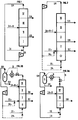
- FIG. 5 A common part of the device which is the subject of the present invention is shown diagrammatically in FIG. 5.
- This device comprises a certain number (favorably from 3 to 24) of chromatographic columns made up of sections or cylinders filled with a lining of a porous medium called stationary phase, which columns (C k ) whose walls are thermally insulated, are connected to each other in series and are percolated by an eluent (compressed gas, supercritical fluid or subcritical liquid) circulated by a compressor K or a pump with a mass flow carefully kept constant; the introductions of the mixture to be fractionated and of an eluent make-up as well as the withdrawals of a mixture called raffinate and of a mixture called extract are carried out between some of the columns (C k and C k + 1 ) as described above. has seen in Figure 1, all of these columns appearing separated for example into four areas.
- the method will be implemented in such a way that the eluting power of the elution fluid will be maintained substantially constant in each of these zones, but will be different from one zone to the other, with the fundamental difference of what is achieved in the processes described above using a liquid eluent.
- the implementation of the fractionation preferably requires the cadenced movement, at a fixed time interval ⁇ t, of the points of introduction of the eluent supply and of the mixture to be separated on the one hand, of the points of sampling of the raffinate and of the extract on the other hand, said points delimiting the four above-defined zones for passing from the intervals between the sections or columns (C k ) and (C k + 1 ) to the intervals between the sections or columns (C k + 1 ) and (C k + 2 ), which four zones will therefore move at the rate ⁇ t in the direction of the flow of the eluent (simulated counter-current) or in the opposite direction (simulated co-current).
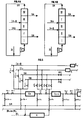
- each column C k is connected to the next one C k + 1 via an all-or-nothing valve V k then a pressure regulating valve U k .
- the eluent at the outlet of the column C k and that coming from the recycling draw-off point SR possibly added with fresh eluent IE is recompressed in the compressor K or the pump via the on-off valves V ' k and V'' k respectively connected to the withdrawal line SR and to the recycling solvent injection line IR, the valves V k and U k then being closed.
- the extract sampling line SB is connected to a pressure regulating valve so as to regulate the pressure in the section of column C k , and is connected downstream of the valve U k and upstream of the column C k + 1 via a valve W k .
- This valve W k controlling the extraction of extract (SB) opens once per cycle. At this time, the valves V k and U k are open, the valves W 1 to W k-1 and W k + 1 to W n are closed, as well as the valves W ' k , W'' k and W ''' k .
- the raffinate sampling line SA is connected to a flow rate regulating valve so as to take a constant flow rate and is connected downstream of the valve U k and upstream of the column C k + 1 va a valve W ′ k .
- This valve W ' k controlling the withdrawal of raffinate SA opens once per cycle.
- the valves V k and U k are open while the valves W ' 1 to W' k-1 and W ' k + 1 to W' n are closed as well as the valves W k , W '' k and W ''' k .
- the lines IA + B and IE2 are each connected to a compressor or a separate pump, so as to deliver constant flow rates.
- Line IA + B is connected downstream of valve U k and upstream of column C k + 1 via a valve W ''' k .
- This valve controlling the mixture injection opens once per cycle. At this time the valves V k and U k are open, the valves W k , W ' k and W'' k are closed as well as the valves W''' 1 to W ''' k-1 and W''' k + 1 to W ''' n .
- valve W '' k controls the injection of solvent of lower density IE2 upstream of the column C k + 1 .
- This line is to be taken into account only when the injected mixture comprises three constituents ABC. In this case, a direct debit line for the SC extract must be added.
- the extraction points of the extract are distinct and are placed between C k and V k and are not represented in FIG. 5.
- the U valves marked open can be either totally open or partly open so as to regulate a difference in pressure between C k and C k + 1 .
- the feed of the mixture to be separated can be carried out either directly without prior dilution if the mixture is liquid at temperature and the supply pressure is more generally and more favorably after dilution of said mixture in the eluent itself previously carried or after this dilution under conditions similar to those desired by the operator in the zone considered (zone III according to the figure 1).
- This dilution operation is carried out conventionally according to the rules of the art: also by way of non-limiting example, this operation can be favorably carried out by dissolving the solid mixture to be fractionated within the percolating eluent on a bed of the solid, which eluent is then finding under conditions where its solvent power is fixed in such a way that it reaches the desired concentration in mixture by saturation: from even, if the mixture is liquid, we can favorably percolate the eluent as bubbles within the mixture under conditions where it is saturates the mixture, reaching the desired composition: if the mixture to fractionation is gaseous or liquid, we can also favorably achieve dissolution in the eluent by in-line mixing, the two flows being carefully regulated.
- the feed to be separated will preferably be gaseous or optionally liquid. We can then carry out the possible dissolution of the liquid charge in the gaseous eluent by example.
- This supply of the mixture to be separated is favorably carried out at a temperature and at a pressure very close to those fixed for the zone considered (zone III); the disturbances of the flow regime and of the chromatographic regime in the downstream columns are thus minimized.
- this feed can be used as an enthalpy supply to the system; in fact, the most favorable implementation of the process consists, as described above, in carrying out the isenthalpic variations in pressure through the control valves (denoted by (U k )): in certain cases, said expansion may s' accompanied by a significant drop in the temperature of the fluid which it is possible to compensate for by introducing the mixture to be fractionated at a temperature above said temperature of the fluid.
- the compression of the fluid within the compressor (K) is generally a source of heating of said fluid: it is possible to counterbalance this heating by introducing the additional eluent at a temperature lower than that of the fluid obtained from the last. upstream column.
- the raffinate and the extract withdrawn from the process itself are solutions of fractionated or separated products, within a certain quantity eluent.
- the application of the prior art as described for example in the aforementioned French patent FR-A-2584618 makes it possible to separate the eluent from the products, said eluent being able to be favorably recycled in the process via make-up by eluting: one of the important advantages of the process being of the invention lies precisely in the easy implementation of this operation, where, unlike the problems encountered when the eluent is a conventional liquid solvent, this separation does not require devices complex, nor of great energy consumption: moreover, when the eluent is, for example, pure carbon dioxide, fractionated products are not generally not polluted by any trace of residual organic solvent, which constitutes a considerable additional advantage.
- the pressure variations between the different zones can be low (pressure drops only) but preferably, at least one pressure modulation between two successive zones can be achieved by means of the pressure regulating valves U k of figure 5.
- FIG. 4A shows two improvements to the variant described in Figure 1, with the same references. Between zones I and II, is interposed a zone Z (FIG. 4A) defined upstream by the point of extraction of the extract and downstream via a point where part of the the extract substantially free of the eluent.
- zone Z defined upstream by the point of extraction of the extract and downstream via a point where part of the the extract substantially free of the eluent.
- the zone Z can be interposed between the zones III and IV and defined upstream by a reinjection point of part of the raffinate substantially free of the eluent and by the draw-off point of the raffinate downstream. This part of the raffinate can therefore be injected upstream of the zone Z.
- the pressure variations between the successive zones can be small (pressure losses only).
- at least two and at most four successive pressure levels can be created by means of at least one and at most three of the pressure regulation valves (U k-1 , U k , U k + 1 ) of Figure 5.
- At least two and at most five levels of separate pressure can be modulated in all zones, the pressure decreasing at least with each withdrawal and preferably at least two pressure levels other than those existing between zones 0 and I.
- at least one and at most four of the expansion valves connected on one side to the all-or-nothing valves and on the other to the columns k, k + 1, etc. are active and preferably at least one valve other than that existing between zones 0 and I.
- zone IV in figure 2 it is possible replace zone IV in figure 2 by allowing the mixture from the zone III in an expansion valve D, then possibly in a component refrigeration or reheating R and in a separator. The raffinate is then collected while the separated eluent is recycled by the compressor K to the injection pressure upstream of zone 0.
- This variant can be justified for the same reasons which were described during the description of the figure 3A.
- the variations in pressure levels between zones can be low (pressure drops only) but preferably the pressure can be modulated at the rate of at least one pressure interval between two successive withdrawals, the pressure decreasing at least with each withdrawal.
- the invention finds many applications in fractionations of mixtures and separations of components from, by example, from the chemical, food and pharmaceutical industries, as well than refining and petrochemicals.
- the device is made as described above in Figure 1 comprising twelve chromatographic columns or sections which are cylinders 30 cm long and 6 cm in diameter filled with a phase stationary consisting of particles of octadecyl grafted silica (RP 18) of a average diameter of the order of 35 ⁇ m, connected in series with the system of valves and compression described above.
- RP 18 octadecyl grafted silica
- the eluent consists of pure carbon dioxide. No heat exchanger is only installed in series between the columns.
- Several fractionation modes according to the process forming the subject of the invention have been implemented, according to the isobaric regime at substantially constant pressure in the 4 zones, close to 146 bars, temperature equal to 40 ° C on the one hand, according to the modulated elution power regime, in two different cases, on the other hand.
- the operating parameters and results of the fractionation obtained when the steady state is reached are presented below:
- Mass flow rate of the mixture to be separated 1.8 kg / h consisting of 0.100 kg / h of the mixture of naphthalene derivatives dissolved in 1.7 kg / h of carbon dioxide at 150 bar and 40 ° C.
- Mass flow rate for withdrawing the raffinate consisting of 0.050 kg / h naphthalene derivatives dissolved in 2.45 kg / h of carbon dioxide: 2.5 Kg / h.
- Mass flow rate of extraction of the extract consisting of 0.050 kg / h naphthalene derivatives dissolved in 2.55 kg / h of carbon dioxide: 2.6 kg / h.
- Mass flow rate leaving the compressor 37.2 kg / h.
- composition of the raffinate (after separation of CO 2 ): 88% of 2-methylnaphthalene.
- composition of the extract (after separation of CO 2 ): 89% in 1-methylnaphthalene.
- the pressure drop in the 12 columns or sections is very low making it possible to consider the regime at substantially constant pressure.
- the delay period is 10 minutes.
- Mass flow rate of the mixture to be separated 1.8 kg / h consisting of 0.100 kg / h of the mixture of naphthalene derivatives dissolved in 1.7 kg / h of pure carbon dioxide at 150 bar and 37 ° C.
- Mass flow rate for withdrawing the raffinate consisting of 0.050 kg / h naphthalene derivatives dissolved in 2.45 kg / h of carbon dioxide: 2.5 kg / h.
- Mass flow rate of extraction of the extract consisting of 0.050 kg / h naphthalene derivatives dissolved in 2.55 kg / h of carbon dioxide: 2.6 kg / h.
- Mass flow rate leaving the compressor 37.2 kg / h.
- composition of the raffinate (after separation of CO 2 ): 94.5% of 2-methylnaphthalene.
- composition of the extract (after separation of CO 2 ): 93.5% 1-methylnaphthalene.
- the pressure drop in the 12 columns or sections is also negligible, and in addition we can consider the regime as isothermal.
- the delay period is 10 minutes.
- Mass flow rate of the mixture to be separated 6 kg / h consisting of 0.100 kg / h of the mixture of naphthalene derivatives dissolved in 5.9 kg / h of pure carbon dioxide at 135 bar and 40 ° C.
- Mass flow rate for withdrawing the raffinate consisting of 0.050 kg / h naphthalene derivatives dissolved in 5.05 kg / h of carbon dioxide: 5.1 kg / h.
- Mass flow rate of extraction of the extract consisting of 0.050 kg / h naphthalene derivatives dissolved in 2.55 kg / h of carbon dioxide: 2.6 kg / h.
- Mass flow rate leaving the compressor 35 kg / h.
- composition of the raffinate (after separation of CO 2 ): 99.8% 2-methylnaphthalene.
- composition of the extract (after separation of CO2): 99.7% in 1-methylnaphthalene.
- the pressure drop in the 12 columns or sections is very low, and moreover we can consider the regime as isothermal.
- the period delay is 10 minutes.
- the method forming the subject of the invention has been implemented in fields where carbon dioxide is a so-called subcritical liquid under pressure substantially constant on the one hand, in power modulation regime elution on the other hand.
- the pressure drop in the 12 columns or sections is very weak.
- the delay period is 10 minutes.
- Example 2a we work with a liquid eluent subcritical, (pressure greater than critical pressure, temperature below at critical temperature).
- Example 2a is carried out under pressure practically constant and gives contents of 88 and 90%;
- example 2b with graduated pressures and pressure stages with number of columns or variable section from one zone to another (1-5-5-1) gives very high of 99.8 and 99.9%.
- Example 3 Separation of two isomers of pentane on a sieve molecular 5A illustrating the use of a compressed gaseous eluent according to the invention
- the densities of the adsorbed phase and the liquid phase are approximately equivalent: the separation which is carried out on 1 g of adsorbed material is found in part canceled by dilution with 3 g of unadsorbed material.
- the densities respective adsorbed and vapor phases are in a ratio of 20 to 500 depending on the pressure involved.
- zone I the internal flow rate is 78 t / h, at the entrance of this zone we 31 t / h of elution solvent is injected and 26.5 t / h of extract is collected at the outlet.
- the internal flow rate is 51.5 t / h.
- zone III the internal flow rate is 101.5 t / h; at the entrance of this zone, 50 t / h of feed is injected and 54.5 t / h of raffinate is collected at the exit.
- zone IV the internal flow rate is 47 t / h, this flow rate is recycled to the inlet of zone I by a pump.
- the total cycle time is 9 minutes.
- zone I the internal flow rate is 26 t / h; at the entrance to this area 24.5 t / h of elution solvent are injected and 23.5 t / h of extract is collected at its exit.
- the internal flow rate is 2.5 t / h.
- zone III the internal flow rate is 52.5 t / h; at the entrance of this 50 t / h of feed is injected into the zone and 51 t / h of raffinate is collected at the outlet.
- zone IV the internal flow is 1.5 t / h, this flow is recycled to the entry of zone I by a compressor.
- the compressibility coefficient of the eluent under these conditions is 0.94.
- Example 3b There are five beds of 3.75 m 3 each and the changeover period is set at 1 minutes 30 seconds, there are two beds in zone I, one bed in zone II, two beds in zone III; the total cycle time is 7 minutes 30 seconds.
- the installation is simplified and 17% of the operating sieve inventory is saved.
- zone I the pressure and the temperature are respectively 100 ° C and 46 bar, the internal flow rate is 31.5 t / h; at the entrance to this area we 24 t / h of solvent is injected and 23.5 t / h of extract is collected at its outlet.
- zone II the pressure and the temperature are respectively 100 ° C and 46 bar, the internal flow rate is 8 t / h.
- zone I and II the compressibility of ethane is 0.82.
- zone III the pressure and the temperature are respectively 90 ° C and 4.8 bar, the internal flow rate of 58 t / h; at the entrance to this area we inject 50 t / h of charge and at its outlet, 50.5 t / h of raffinate is collected.
- zone IV the pressure and the temperature are respectively 90 ° C and 4.8 bar, internal flow 7.5 t / h
- the compressibility coefficient of ethane under the conditions of zones III and IV is 0.98.
- zone IV to zone I does not take place at a constant flow rate at the outlet of zone IV since it is a column expansion of this zone. from 46 to 4.8 bar.
- zone II does not have a constant flow rate at its inlet since it must be repressurized from 4.8 bar to 46 bar.
- the isopentane purity and yield results are equivalent for the four examples 3a, 3b, 3c, 3d: purity of isopentane in the raffinate greater than 98%, isopentane yield in the raffinate greater than 98%.
- the devices and methods according to the invention allow therefore to achieve surprising results by the contents and yields with eluents at a pressure greater than or equal to the critical pressure and at higher or equal temperature (supercritical fluid), or lower (liquid subcritical) at the critical temperature, or even with gaseous eluents tablets, at a pressure lower than the critical pressure, and having a compressibility coefficient significantly different from 1, the temperature which may be either above or below the critical temperature.
- the mixture to be fractionated consists of 1 -methylnaphthalene (33% by mass), 2-methylnaphthalene (33% by mass) and compounds heavier assimilable to isomers of trimethylnaphthalene (33% in mass).
- the apparatus (figure 2), comprises fifteen columns or sections chromatography which are cylinders 30 cm long and 6 cm of diameter filled with a stationary phase consisting of particles of octadecyl grafted silica (RP 18) with an average diameter of the order of 35 micrometers, connected in series with the valve and compressor system described below.
- RP 18 octadecyl grafted silica
- the eluent consists of pure carbon dioxide. No heat exchanger is only arranged in series between the columns.
- Several modes of operation according to the method forming the subject of the invention have been implemented according to the two-state pressure regime described in patent FR-A-2651149, (zone 0 and zones I, II, III and IV) and according to the regime at pressure modulation described in the present invention on the other hand.
- the mixture to be fractionated consists of 2,5-bromothiophene (33% by mass), 3.4 dibromothiophene (33% by mass) and 2,3,4,5-tetrabromothiophene (33% by mass).
- the device is identical to the one used in the previous example and in Example 1 ( Figure 3).
- the eluent used is trifluorobromethane (CF 3 Br) whose critical coordinates are 39.7 bar and 67 ° C.
- CF 3 Br trifluorobromethane
- Several operating modes of the apparatus and according to the method forming the subject of the invention were implemented according to the regime at substantially constant pressure in the five zones close to 70 bar, (temperature equal to 80 ° C) d 'on the one hand, and on the other hand according to the pressure modulation regime described in the present application.
- zone 0 one: zone I: three: zone II: five: zone III: five: zone IV: one.
- the lag period is set at 3.3 minutes in all cases.
- FIG. 5 diagrammatically shows the assembly of two zones, columns or sections of columns C k and C k + 1 .
- valves with total opening / closing ( ⁇ all or nothing ⁇ ) V '' 'and the control valve U said valve U makes it possible to expand the fluid at the inlet pressure in zone I (line denoted IR2) and can advantageously be operated by regulating the flow in this branch of the circuit; said valves V '' 'are operated under the same conditions as the V'k valves. If the operator does not wish to use this recycling between zones (0 and I, figures 1 to 4), it can close both the U valve and all of the valves V '' ', all of the eluting fluid then being distributed by the line denoted IR1.
- the solvent is condensed in a heat exchanger heat and it is stored in an intermediate tank which makes it possible to obtain more regular pumping; the compressed fluid from the pump is then brought to working temperature thanks to a heat exchanger.
- the system is conventionally used in fluid extraction / fractionation supercritical and has not been shown in the figures.
Description
La présente invention se rapporte à un dispositif et à un procédé industriel de fractionnement de mélanges de composants, de préférence liquides, mais aussi solides ou gazeux, par chromatographie, l'éluant étant soit à pression supercritique, c'est-à-dire un fluide en état supercritique ou un liquide subcritique, soit étant à l'état gazeux sous forme d'un gaz comprimé.The present invention relates to a device and a method industrial fractionation of mixtures of components, preferably liquids, but also solids or gases, by chromatography, the eluent being either at supercritical pressure, that is to say a fluid in a supercritical state or a subcritical liquid, or being in the gaseous state in the form of a compressed gas.
Il convient de rappeler que la chromatographie est basée sur le principe suivant : dans un contenant généralement cylindrique appelé la colonne contenant un garnissage constitué par un corps solide poreux perméable aux fluides et que l'on appelle phase stationnaire, on fait passer le mélange fluide dont on veut séparer les constituants. Le garnissage est par exemple constitué par un gel ou une agglomération de particules pulvérulentes, le fluide qui le traverse étant constitué soit par le mélange fluide dont il convient de séparer les constituants, soit par un mélange dissous dans un fluide solvant que l'on appelle l'éluant. La vitesse de passage des différents constituants à travers le solide perméable dépend des caractéristiques physico-chimiques des différents constituants de sorte qu'à la sortie de la colonne les constituants sortent successivement et sélectivement. Certains des constituants ont tendance à se fixer fortement dans la masse solide et donc à être plus retardés, d'autres au contraire ont peu tendance à se fixer et sortent rapidement avec l'éluant lui-même.It should be remembered that chromatography is based on the following principle: in a generally cylindrical container called the column containing a packing consisting of a porous solid body permeable to fluids and called the stationary phase, the fluid mixture of which we want to separate the constituents. The filling is by example consisting of a gel or an agglomeration of particles pulverulent, the fluid which passes through it consisting either of the mixture fluid, the constituents of which should be separated, either by a dissolved mixture in a solvent fluid called the eluent. The speed of passage of different constituents through the permeable solid depend on the physico-chemical characteristics of the various constituents so that at the leaving the column, the constituents exit successively and selectively. Some of the constituents tend to bind strongly in the mass solid and therefore to be more delayed, others on the contrary have little tendency to attach and come out quickly with the eluent itself.
Il faut rappeler que les corps sont généralement connus sous trois états : solide, liquide et gazeux. On passe de l'un à l'autre en faisant varier la température et/ou la pression. Or il existe un point au-delà duquel on peut passer de l'état liquide à l'état gaz ou vapeur sans passer par une ébullition ou à l'inverse par une condensation, mais de façon continue : ce point est appelé le point critique.It should be remembered that bodies are generally known as three states: solid, liquid and gas. We go from one to the other by doing vary the temperature and / or pressure. Now there is a point beyond which we can pass from the liquid state to the gas or vapor state without passing through a boiling or conversely by condensation, but continuously: this point is called the critical point.
On sait qu'un fluide en état supercritique, c'est-à-dire dans un état caractérisé soit par une pression et une température respectivement supérieures à la pression et à la température critiques dans le cas d'un corps pur, soit par un point représentatif (pression, température) situé au-delà de l'enveloppe des points critiques représentés sur un diagramme (pression, température) dans le cas d'un mélange, présente, pour de très nombreuses substances, un pouvoir solvant élevé sans commune mesure avec celui observé dans ce même fluide à l'état de gaz comprimé : il en est de même des liquides dits subcritiques c'est-à-dire dans un état caractérisé soit par une pression supérieure à la pression critique et par une température inférieure à la température critique dans le cas d'un corps pur, soit par une pression supérieure aux pressions critiques et une température inférieure aux températures critiques des composants dans le cas d'un mélange (cf. EP-A-0 127 926).We know that a fluid in a supercritical state, that is to say in a state characterized either by pressure and temperature respectively greater than the critical pressure and temperature in the case of a body pure, or by a representative point (pressure, temperature) located beyond the envelope of the critical points represented on a diagram (pressure, temperature) in the case of a mixture, present, for very many substances, a high solvent power without commonality with that observed in this same fluid in the state of compressed gas: it is the same so-called subcritical liquids, that is to say in a state characterized either by a pressure higher than the critical pressure and by a temperature lower than the critical temperature in the case of a pure substance, either by a pressure above critical pressures and a temperature below critical temperatures of the components in the case of a mixture (cf. EP-A-0 127 926).
Les variations importantes et modulables du pouvoir solvant de ces fluides sont d'ailleurs utilisées dans de nombreux procédés d'extraction (solide/fluide), fractionnement (liquide/fluide), de chromatographie analytique ou préparative, de traitement des matériaux (céramiques, polymères...) ; des réactions chimiques ou biochimiques sont également réalisées dans de tels solvants.The large and adjustable variations in the solvent power of these fluids are also used in many extraction processes (solid / fluid), fractionation (liquid / fluid), analytical chromatography or preparatory, treatment of materials (ceramics, polymers, etc.); from chemical or biochemical reactions are also carried out in such solvents.
L'un des avantages principaux des procédés mettant en oeuvre les fluides à pression supercritique réside dans la facilité de réaliser la séparation entre le solvant (le fluide) et les extraits et solutés, ainsi qu'il a été décrit dans de nombreuses publications et, pour certains aspects importants de mise en oeuvre, dans le brevet FR-A-2584618.One of the main advantages of the processes using fluids at supercritical pressure lies in the ease of carrying out the separation between the solvent (the fluid) and the extracts and solutes, as has been described in numerous publications and, for some important aspects implementation, in patent FR-A-2584618.
Les propriétés intéressantes de ces fluides sont d'ailleurs utilisées depuis longtemps en chromatographie d'élution, soit à des fins analytiques, soit à des fins de production industrielle selon un procédé décrit dans le brevet FR-A-2527934. L'utilisation de ces fluides a également été décrite comme solvant de désorption de composés retenus sur des absorbants, comme dans plusieurs brevets américains (US-A-4 061 551, US-A-4 124 528, US-A-4 147 624).The interesting properties of these fluids are moreover used for a long time in elution chromatography, either for analytical, or for industrial production according to a method described in patent FR-A-2527934. The use of these fluids has also been described as a desorption solvent for compounds retained on absorbents, as in several US patents (US-A-4,061,551, US-A-4,124,528, US-A-4,147,624).
Les nombreuses études de la chromatographie d'élution utilisant les fluides supercritiques ou liquides subcritiques ont montré un comportement surprenant de ces fluides marqué, en particulier, par la forte dépendance du facteur de capacité (donc du temps de rétention) à la masse volumique et à la température du fluide éluant, propriété qui va être largement exploitée dans le dispositif et le procédé décrits dans la présente invention. De plus, alors que pour les gaz parfaits, c'est-à-dire principalement pour les gaz sous faible pression à des températures nettement plus élevées que leur température d'ébullition à la pression considérée, le facteur de capacité est indépendant de la pression à température constante, cette forte variation du facteur de capacité en fonction de la masse volumique, et donc de la pression si la température est maintenue constante, est non seulement observée pour les fluides à une pression supérieure à la pression critique mais également pour les gaz comprimés c'est-à-dire portés à une pression inférieure à la pression critique mais toutefois supérieure à la pression où ils ont le comportement de gaz parfaits : cette propriété sera exploitée dans le dispositif et le procédé décrits dans la présente invention qui met en oeuvre non pas seulement un éluant à pression supercritique mais également un éluant gazeux porté à une pression suffisante pour qu'apparaisse ce comportement particulier en chromatographie qui a été décrit par de nombreux auteurs dans le cas particulier de la chromatographie analytique d'élution dont par exemple G.M. Schneider, Angew-Chem. Int. Ed. Engl. 17, (1978), p. 716-727 : C.R. Yonker et R.D. Smith, J. of Chromatography 351 (1986), p. 211-218 et 396 (1986), p. 19-29 : M. Perrut and J. Dellacherie, Proc of the 1st symp on supertical fluids Nice 1988; proceedings 2-905-267-13-5, pages 439 à 445.The numerous studies of elution chromatography using supercritical fluids or subcritical fluids have shown a surprising behavior of these fluids marked, in particular, by the strong dependence of the capacity factor (therefore of the retention time) on the mass volume and temperature of the eluting fluid, a property which will be largely exploited in the device and the method described in the present invention. Moreover, while for ideal gases, that is to say mainly for low-pressure gas at temperatures significantly higher than their boiling temperature at the pressure considered, the capacity factor is independent of pressure at constant temperature, this strong variation in capacity factor as a function of density, and therefore of pressure if the temperature is kept constant, is not only observed for fluids at a pressure greater than the critical pressure but also for compressed gases, i.e. brought to a pressure lower than the critical pressure but still higher than the pressure where they have the ideal gas behavior: this property will be exploited in the device and method described in the present invention which implements not only an eluent at supercritical pressure but also a gaseous eluent brought to a sufficient pressure for this particular behavior in chromatography which has been described by many numerous authors in the particular case of analytical chromatography elution including for example G.M. Schneider, Angew-Chem. Int. Ed. Engl. 17, (1978), p. 716-727: C.R. Yonker and R.D. Smith, J. of Chromatography 351 (1986), p. 211-218 and 396 (1986), p. 19-29: M. Perrut and J. Dellacherie, Proc of the 1st symp on supertical fluids Nice 1988; proceedings 2-905-267-13-5, pages 439 to 445.
L'objet de la présente invention est de permettre, à des fins de production industrielle, le fractionnement de mélanges en différentes fractions en utilisant un système chromatographique complexe dérivé dans sa conception générale des procédés classiquement appelés chromatographie à lit mobile simulé utilisés à grande échelle depuis plusieurs décennies et décrits dans plusieurs brevets américains parmi lesquels on citera US-A-2985889, US-A-3696107, US-A-3706812, US-A-3761533, US-A-4402832, ainsi que certains brevets français les FR-A-2 103 302, FR-A-2 651 148 et FR-A-2 651 149.The object of the present invention is to enable, for the purposes of industrial production, splitting mixtures into different fractions using a complex chromatographic system derived in its general design of processes conventionally called chromatography moving bed simulated in use on a large scale for several decades and described in several American patents among which we will mention US-A-2985889, US-A-3696107, US-A-3706812, US-A-3761533, US-A-4402832, as well as certain French patents FR-A-2 103 302, FR-A-2 651 148 and FR-A-2 651 149.
L'invention réside dans le fait que, à la différence desdits procédés mis en oeuvre avec des éluants liquides, pour lesquels les phénomènes de rétention sont indépendants de la pression mise en oeuvre, l'éluant est un fluide supercritique, un liquide subcritique ou un gaz comprimé dont les propriétés physico-chimiques, comme en premier lieu celle décrite ci-dessus relative à la variation du facteur de capacité, permettent une mise en oeuvre très différente de celle classiquement utilisée avec les éluants liquides, voire avec des éluants gazeux de comportement très proche d'un gaz partait, conduisant à des résultats surprenants, extrêmement différents de ceux obtenus avec des éluants liquides ainsi qu'il va être décrit ci-dessous. Ainsi, lorsqu'on travaille avec des éluants liquides, leur pouvoir éluant est très difficile à moduler sauf à changer leur composition, comme c'est le cas par exemple dans les régimes à gradient de composition utilisés classiquement en chromatographie en phase liquide - ce qui pose d'ailleurs de difficiles problèmes de recyclage de ces solvants et conduit à des prix de revient très élevés lorsque l'on met en oeuvre de tels procédés à l'échelle de la production industrielle - ou si l'on fait varier leur température, ce qui est difficile également, compte tenu de l'exigence d'une parfaite homogénéité de la température dans toute section d'une colonne chromatographique - ce qui rend cette possibilité quasi irréalisable à l'échelle industrielle.The invention resides in the fact that, unlike said processes implemented with liquid eluents, for which the retention phenomena are independent of the pressure used, the eluent is a supercritical fluid, a subcritical liquid or a compressed gas whose physicochemical properties, as in the first place that described above relative to the variation of the capacity factor, allow a work very different from that conventionally used with liquid eluents, even with gaseous eluents of behavior very similar to a gas departed, leading to surprising results, extremely different from those obtained with liquid eluents as will be described below. Thereby, when working with liquid eluents, their eluting power is very difficult to modulate except to change their composition, as is the case with example in the composition gradient regimes used conventionally in liquid chromatography - which also poses difficult recycling problems of these solvents and leads to very costly high when such methods are implemented at the scale of the industrial production - or if their temperature is varied, which is also difficult, given the requirement of perfect homogeneity of the temperature in any section of a chromatographic column - which makes this possibility almost impossible on an industrial scale.
La figure 1 permet de comprendre le fonctionnement des procédés classiques dit de chromatographie à contre-courant simulé. Les procédés comprennent un certain nombre n (allant de 4 à 24 classiquement) de colonnes ou tronçon de colonne chromatographiques (Ck) constituées de cylindres remplis d'un garnissage d'un milieu poreux appelé phase stationnaire, lesquelles n colonnes (Ck), maintenues à une même température, sont connectées les unes aux autres en série et sont percolées par un éluant liquide E mis en circulation dans le sens de la flèche par une pompe P (ou compresseur K) à débit soigneusement choisi et arbitrairement disposée entre deux colonnes ou tronçons : les introductions du mélange à séparer IA + B et d'un appoint d'éluant IE ainsi que les soutirages d'un mélange appelé raffinat SA et d'un mélange appelé extrait SB sont réalisés entre certaines des colonnes (Ck) et (Ck+1), l'ensemble de ces colonnes apparaissant séparé par exemple en quatre zones : il a été démontré et utilisé à une très grande échelle, dans plusieurs dizaines d'unités industrielles, que si les débits de circulation de l'éluant délivré par la pompe P ou le compresseur K et les débits d'introduction et soutirage susnommés sont bien choisis, et, si l'on déplace, à espace de temps régulier Δt, les quatre points d'introduction/soutirage délimitant lesdites quatre zones de l'intervalle entre les colonnes (Ck) et (Ck+1) à l'intervalle entre les colonnes (Ck+1) et (Ck+2), on peut obtenir un fractionnement du mélange à séparer en deux fractions nommées raffinat et extrait avec une sélectivité élevée si la phase stationnaire et le solvant d'élution ont été judicieusement choisis. Les avantages de cette mise en oeuvre sont considérables par rapport aux procédés chromatographiques classiques en régime frontal ou en régime d'élution :
- il s'agit, pour l'opérateur, d'un système continu et non d'un système périodique exigeant une gestion difficile :
- la dilution des composants du raffinat et de l'extrait dans le solvant d'élution est beaucoup plus faible : dans certains cas favorables, les composants se retrouvent à la même concentration que dans le mélange de départ, voire même plus concentrés, alors que, dans le cas des procédés classiques en régime d'élution ou en régime frontal, la dilution est couramment de 100 à 1000 d'où résultent des coûts très élevés de manipulation de l'éluant et de la séparation éluant/produits :
- le nombre de plateaux théoriques (au sens des chromatographistes) requis pour un fonctionnement donné est nettement inférieur à celui des procédés classiques susnommés, diminuant ainsi très fortement à la fois le prix de la phase stationnaire nécessaire et des équipements qui fonctionnent classiquement à basse ou moyenne pression (≤ 30 bar; 1 bar = 10-1 MPa).
- For the operator, this is a continuous system and not a periodic system requiring difficult management:
- the dilution of the raffinate and extract components in the eluting solvent is much lower: in certain favorable cases, the components are found at the same concentration as in the starting mixture, or even more concentrated, whereas, in the case of conventional processes in elution regime or in frontal regime, the dilution is commonly 100 to 1000, resulting in very high costs of handling the eluent and of separating the eluent / products:
- the number of theoretical plates (in the sense of chromatographers) required for a given operation is significantly lower than that of the aforementioned conventional processes, thus greatly reducing both the price of the necessary stationary phase and of the equipment which conventionally operates at low or medium pressure (≤ 30 bar; 1 bar = 10 -1 MPa).
C'est pourquoi ce type de procédé a pu se révéler extrêmement économique pour traiter de très gros tonnages de produits à faible coût, comme lors de la purification du paraxylène ou le fractionnement glucose/fructose.This is why this type of process could prove to be extremely economical to process very large tonnages of products at low cost, as in the purification of paraxylene or fractionation glucose / fructose.
On remarquera que la position de la pompe de circulation P de l'éluant reste fixée entre deux colonnes : comme les liquides ne sont pas compressibles, leur pouvoir éluant est indépendant de la pression et reste donc constant dans toutes les zones, quelle que soit la position de la pompe dans chacune de ces zones au cours du temps. On notera également que les nombres de colonnes dans les différentes zones sont en général différents les uns des autres.Note that the position of the circulation pump P of the eluent remains fixed between two columns: since liquids are not compressible, their eluting power is independent of the pressure and remains therefore constant in all zones, whatever the position of the pump in each of these areas over time. Note also that the numbers of columns in the different zones are generally different. from each other.
Dans des versions plus complexes de ce concept de base, il a été proposé de réaliser non pas deux mais trois (ou plus) fractions soutirées en certains points situés entre deux des colonnes (Ck) et (Ck+1), ces points, comme ceux d'introduction de l'appoint d'éluant et du mélange à séparer, étant déplacés à espace de temps régulier ainsi qu'il a été décrit ci-dessus.In more complex versions of this basic concept, it has been proposed to perform not two but three (or more) fractions drawn off at certain points located between two of the columns (C k ) and (C k + 1 ), these points , such as those for introducing the additional eluent and the mixture to be separated, being moved at a regular space of time as has been described above.
EP-A-0 415 822 enseigne un procédé et un dispositif pour le fractionnement de mélanges
par chromatographie à lit mobile simulé. Cependant, le dispositif comprend une seule
vanne de régulation pui est mobile (cf. figure 6). C'est une vanne rotative qui permet
de réguler la pression entre les zones 6 et 5 (correspondant aux zones 0 et I de le
figure 2 de la présente demande), tout le long de la boucle. EP-A-0 415 822 teaches a method and a device for the fractionation of mixtures
by simulated moving bed chromatography. However, the device includes only one
pui control valve is mobile (see figure 6). It is a rotary valve which allows
to regulate the pressure between zones 6 and 5 (corresponding to
La présente invention a pour objet un dispositif de
fractionnement d'un mélange de p composants en p composants ou q
coupes, q étant inférieur ou égal à p, dispositif présentant les caractéristiques telle que
définies dans la revendication 1. The present invention relates to a device for
splitting a mixture of p components into p components or q
sections, q being less than or equal to p, device having the characteristics such that
defined in
La présente invention a également pour objet un procédé de fractionnement chromatographique de mélanges de composants dans une boucle de colonnes ou tronçons de colonnes montés en série, ledit procédé comportant les caractéristiques de la revendication 7. The present invention also relates to a method of chromatographic fractionation of mixtures of components in a loop of columns or sections of columns mounted in series, said method comprising the features of claim 7.
Les critères de choix de l'éluant gazeux peuvent répondre à des impératifs différents voire contradictoires. On peut citer :
- l'écart de volatilité entre les produits de la charge et l'éluant,
- l'aptitude de l'éluant à déplacer les constituants de la charge (dans le cas où l'éluant est adsorbé),
- la compatibilité de l'éluant et de l'adsorbant : par exemple on évitera d'envoyer de la vapeur d'eau sur les zéolithes dans certaines conditions de température et de pression... ou d'envoyer de l'oxygène sur du charbon actif.
- the volatility difference between the products of the feed and the eluent,
- the ability of the eluent to displace the constituents of the feed (in the case where the eluent is adsorbed),
- the compatibility of the eluent and the adsorbent: for example, avoid sending water vapor over the zeolites under certain temperature and pressure conditions ... or sending oxygen over carbon active.
Alors que pour les gaz parfaits, c'est-à-dire principalement les gaz sous faible pression à des températures nettement plus élevées que leur température d'ébullition à la pression considérée, ou encore présentant des valeurs de coefficient de compressibilité (défini par PV/RT), par exemple comprises entre environ 0,95 et 1,05 et de préférence entre 0,98 et 1,02, le facteur de capacité est indépendant de la pression à température constante, une forte variation du facteur de capacité en fonction de la masse volumique, (et donc de la pression si la température est maintenue constante), est non seulement observée pour les fluides à une pression supérieure à la pression critique mais également pour les gaz comprimés c'est-à-dire portés à une pression inférieure à la pression critique mais toutefois supérieure à la pression où ils ont le comportement de gaz parfaits. La pression sera telle que le coefficient de compressibilité soit sensiblement différent de 1.While for ideal gases, that is to say mainly gases under weak pressure at temperatures significantly higher than their temperature boiling at the pressure considered, or else having values of compressibility coefficient (defined by PV / RT), for example between about 0.95 and 1.05 and preferably between 0.98 and 1.02, the capacity factor is independent of pressure at constant temperature, a strong variation of the capacity factor as a function of the density, (and therefore of the pressure if the temperature is kept constant), is not only observed for fluids at a pressure greater than the critical pressure but also for compressed gases that is to say brought to a pressure lower than the critical pressure but still higher than the pressure where they have the behavior of ideal gases. The pressure will be such that the compressibility coefficient is significantly different from 1.
Selon une mise en oeuvre particulière du procédé, l'éluant peut être injecté dans la boucle à une température différente de la température opératoire. Il peut dans certaines conditions se refroidir ou se réchauffer au contact de l'adsorbant par exemple. According to a particular implementation of the process, the eluent can be injected into the loop at a temperature different from the temperature operative. It may under certain conditions cool down or heat up in the contact of the adsorbent for example.
De
préférence, la pression décroít dans chaque zone. Par exemple, dans le cas
d'un dispositif adapté à la séparation de trois composants avec quatre
zones 0, I, II, III ou cinq zones 0, I, II, III et IV, la pression peut décroítre d'au
moins un intervalle entre deux points de soutirage autres que le point de
soutirage de l'extrait SC existant entre les zones 0 et I et de préférence au
moins un organe de réduction de pression ou de détente supplémentaire peut
être rajouté entre la zone 0 et la zone I au dispositif ci-dessus, de sorte que
la pression décroít entre chaque zone.Of
preferably, the pressure decreases in each zone. For example, in the case
a device suitable for the separation of three components with four
Selon une variante avantageuse du procédé, on peut ajuster la pression dans la zone III en amont de laquelle a été injecté le mélange AB ou ABC, à une valeur inférieure d'au moins 1 bar et de préférence de 3 à 100 bar à la pression régnant dans la zone II.According to an advantageous variant of the method, it is possible to adjust the pressure in zone III upstream of which the mixture AB was injected or ABC, at a lower value of at least 1 bar and preferably from 3 to 100 bar at the pressure prevailing in zone II.
Selon une variante ayant l'avantage d'éviter la zone la plus en aval
(zone IV), on peut détendre et séparer par des moyens appropriés (une
vanne de détente, suivie éventuellement d'une réfrigération ou d'un
réchauffage ou encore une colonne à distiller par exemple) la totalité de
l'éluant et du raffinat en aval d'une zone en amont de laquelle a été injecté le
mélange à séparer : on recueille le raffinat et on recycle le courant de
recyclage de l'éluant à la pression d'injection dans la zone 0 grâce au
compresseur ou à la pompe.According to a variant having the advantage of avoiding the most downstream zone
(zone IV), one can relax and separate by appropriate means (a
expansion valve, possibly followed by refrigeration or
reheating or a distillation column for example) all of
the eluent and the raffinate downstream of a zone upstream of which the
mixture to be separated: the raffinate is collected and the stream of
recycling of the eluent at the injection pressure in
Dans le cas où l'on veut séparer un mélange de deux composants dans le dispositif selon l'invention, on peut, selon une première variante du procédé, détendre et séparer par des moyens appropriés (une vanne de détente par exemple suivie éventuellement d'une réfrigération ou d'un réchauffage ou encore une colonne à distiller) la totalité de l'éluant et du raffinat en aval d'une zone III en amont de laquelle a été injecté le mélange AB. On recueille alors le raffinat et on recycle le courant de recyclage de l'éluant à la pression d'injection dans la zone I grâce au compresseur ou à la pompe. Cette variante présente l'avantage d'éviter la quatrième et dernière zone.If you want to separate a mixture of two components in the device according to the invention, it is possible, according to a first variant of the process, relax and separate by appropriate means (a expansion valve, for example, possibly followed by refrigeration or reheating or a distillation column) all of the eluent and the raffinate downstream of a zone III upstream of which the AB mixture. The raffinate is then collected and the stream is recycled. recycling of the eluent at the injection pressure in zone I thanks to the compressor or pump. This variant has the advantage of avoiding fourth and last zone.
Selon une deuxième variante du procédé relative à la séparation d'un mélange de deux composants, on peut introduire une partie de l'extrait sensiblement débarrassé de l'éluant en aval d'une zone Z entre la zone I et la zone II, définie en amont par le point de soutirage de l'extrait (SB) et en aval par un point de réinjection (IRB) de la partie de l'extrait B sensiblement débarrassé de l'éluant.According to a second variant of the process relating to the separation of a mixture of two components, part of the extract can be introduced substantially free of the eluent downstream of a zone Z between zone I and zone II, defined upstream by the extraction point of the extract (SB) and in downstream by a reinjection point (IRB) of the part of the extract B substantially rid of the eluent.
Selon une troisième variante du procédé relative à la séparation d'un mélange de deux composants, on peut introduire une partie du raffinat sensiblement débarrassé de l'éluant en amont d'une zone Z située en aval de la zone III, définie en amont par un point de réinjection (IRA) de la dite partie du raffinat sensiblement débarrassé de l'éluant et en aval par le point de soutirage du raffinat (SA).According to a third variant of the process relating to the separation of a mixture of two components, part of the raffinate can be introduced substantially free of the eluent upstream of a zone Z situated downstream of zone III, defined upstream by a reinjection point (ARI) of said part of the raffinate substantially free of the eluent and downstream through the point raffinate withdrawal (SA).
Bien entendu, selon ces deux variantes, la pression d'injection (IRB ou IRA) sera telle que la pression dans la zone en aval du point d'injection sera au plus égale à la pression dans la zone immédiatement en amont.Of course, according to these two variants, the injection pressure (IRB or IRA) will be such that the pressure in the area downstream of the injection point will be at most equal to the pressure in the zone immediately upstream.
Selon une dernière variante, le pression décroít entre chaque zone à partir de le zone recevant l'éluant. According to a final variant, the pressure decreases between each zone from the zone receiving the eluent.
Dans ce qui suit et par simplification on se limitera au cas où p et q sont égaux à 2 c'est-à-dire correspondant à un mélange de deux composants à séparer en deux coupes, ce qui donne un circuit à n points d'injection d'éluant, n points d'injection de mélange, (soit au plus 2n points d'injection en tout), n points de soutirage d'extrait, n points de soutirage de raffinat (soit au plus 2 n points de soutirage en tout ); avantageusement ces 4 n points d'injection et soutirage seront confondus en n points. Ceci donne un circuit comprenant successivement et en série un courant d'injection d'éluant, un courant de soutirage d'extrait, un courant d'injection de mélange à fractionner et un courant de soutirage de raffinat, chacun de ces courants étant alternativement connectés aux n points d'injection-soutirage situés entre deux colonnes successives.In what follows and by simplification we will limit ourselves to the case where p and q are equal to 2, i.e. corresponding to a mixture of two components to be separated into two sections, resulting in an n-point circuit eluent injection, n mixture injection points, (i.e. at most 2n points injection in total), n extraction points of extract, n points of withdrawal of raffinate (ie at most 2 n draw-off points in all); advantageously these 4 n injection and withdrawal points will be merged into n points. This gives a circuit comprising successively and in series an injection current eluent, an extract draw-off stream, a mixture injection stream to be fractionated and a raffinate withdrawal stream, each of these streams being alternately connected to the n injection-withdrawal points located between two successive columns.
Entre deux points successifs d'injection ou de soutirage on peut prévoir une ou plusieurs colonnes ou tronçons de colonnes en série. Dans ce qui suit, également on considérera, pour faciliter la compréhension, des colonnes successives et espacées les unes des autres montées en série et de mêmes caractéristiques dimensionnelles. Il est évident qu'il est possible de considérer chaque zone comme étant définie non pas par une colonne individuelle mais par un ou des tronçon(s) inclus dans une colonne plus longue, ce qui, à la limite, pourrait se traduire par une seule colonne avec un circuit de circulation de l'éluant entre les deux extrémités de la colonne, par exemple. En fait, utiliser un certain nombre de colonnes, même divisées en tronçons, facilite en pratique la mise en place et le tassement du garnissage ainsi que son extraction en fin d'opération en vue d'un renouvellement.Between two successive injection or withdrawal points, we can provide one or more columns or sections of columns in series. In this which follows, also, to facilitate understanding, we will consider successive columns spaced apart from each other mounted in series and of the same dimensional characteristics. It is obvious that it is possible to consider each zone as being defined not by a column individual but by one or more section (s) included in a column more long, which ultimately could result in a single column with a circulation circuit of the eluent between the two ends of the column, by example. In fact, using a number of columns, even divided into sections, facilitates in practice the installation and the packing of the packing as well as its extraction at the end of the operation for renewal.
Pour fixer les idées et le vocabulaire, on commencera, en se reportant à la figure 1 , par schématiser le principe de fonctionnement du dispositif et du procédé correspondant à un lit mobile à contre-courant simulé en considérant une colonne chromatographique verticale divisée en tronçons, plus précisément ici en quatre tronçons superposés correspondant successivement à la zone I, la zone II, la zone III et la zone IV en partant du bas de la colonne. L'éluant est introduit, par un compresseur K, à la partie inférieure de la colonne en IE et le mélange de composants A et B entre les zones II et III en IA+B. Les composants A et B sont soutirés sous forme d'extrait contenant essentiellement le composant B en SB entre la zone I et la zone II et sous forme de raffinat contenant essentiellement le composant A en SA entre la zone III et la zone IV. Sur cette figure 1, l'éluant circule donc de bas en haut. Comme on le verra par la suite, on va introduire un décalage relatif des points d'injection et de soutirage (par rapport à la phase solide) ce qui simulera un décalage de la phase solide vers le bas. On remarquera, à ce sujet, qu'en pratique, il vaut mieux ne pas déplacer la phase solide de garnissage vers l'amont par rapport aux points d'injection et de soutirage, mais de maintenir le garnissage solide fixe et de déplacer relativement les points d'injection et de soutirage en les décalant périodiquement d'une zone, dans le même sens que la circulation de l'éluant c'est-à-dire vers l'aval. Si on revient à la figure 1, les fluides circulant de bas en haut, le mélange A + B est injecté entre la zone II et la zone III, c'est-à-dire à mi-hauteur et les composants vont se répartir chromatographiquement par interactions entre composants et phase stationnaire, par exemple par adsorption, dans le garnissage solide. Les composants à plus forte affinité avec la phase solide seront donc plus difficilement entraínés par l'éluant et ne le suivront qu'avec retard, tandis que les composants à affinité plus faible auront tendance à être plus facilement entraínés par l'éluant et donc à sortir prioritairement. Si l'on veut que le composant à plus faible affinité, ici A, sorte de la colonne entre la zone III et la zone IV et si l'on veut que le composant à plus forte affinité, ici B, sorte de la colonne entre la zone I et la zone II, il est préférable d'opérer dans les conditions suivantes :
- Dans la zone I, il faut favoriser une forte élution c'est-à-dire débit d'éluant et/ou un fort pouvoir solvant pour empêcher B de sortir par le bas lors du décalage vers le bas du garnissage, ce qui permet à ce composant B à plus forte affinité d'être soutiré entre la zone I et la zone II.
- Dans la zone II, il convient que le composant A à plus faible affinité remonte en suivant l'éluant pour ne pas sortir vers le bas avec B mais par contre, il faut que B reste fixé par le solide pour descendre ensuite de la zone II à la zone I et de la zone I vers la sortie avec le décalage successif des zones de garnissage chromatographique. Ceci nécessite une élution faible et donc un débit d'éluant et/ou un pouvoir solvant plus faible dans la zone II que dans la zone i.
- Dans la zone III, il faut que le composant A à plus faible affinité, soit entraíné par l'éluant pour être soutiré en A entre la zone III et la zone IV, alors que le composant B doit rester fixé dans le solide et descendre de la zone III vers la zone II lors du décalage. Ceci veut dire que une élution faible et donc un débit d'éluant et/ou le pouvoir solvant ne doivent pas être supérieur dans la zone III à ce qu'ils sont que dans la zone II, c'est-à-dire qu'ils peuvent être égaux ou inférieurs.
- In zone I, it is necessary to promote a strong elution, that is to say flow rate of eluent and / or a strong solvent power to prevent B from leaving the bottom during the downward shifting of the packing, which allows this component B has a higher affinity to be withdrawn between zone I and zone II.
- In zone II, component A with a lower affinity should rise while following the eluent so as not to exit downwards with B, but on the other hand, B must remain fixed by the solid in order to then descend from zone II to zone I and from zone I to the outlet with the successive offset of the chromatographic packing zones. This requires a low elution and therefore a flow rate of eluent and / or a lower solvent power in zone II than in zone i.
- In zone III, it is necessary that the component A with lower affinity, is driven by the eluent to be withdrawn in A between zone III and zone IV, while component B must remain fixed in the solid and descend from zone III towards zone II during the shift. This means that a low elution and therefore an eluent flow rate and / or the solvent power must not be greater in zone III than they are in zone II, that is to say that they can be equal or less.
Dans la zone IV, il faut que le composant A ne soit pas entraíné avec l'éluant en recyclage de sorte que l'élution donc le débit d'éluant et/ou le pouvoir solvant soit plus faible que dans cette zone III.In zone IV, component A must not be trained with the eluent in recycling so that the elution therefore the eluent flow rate and / or the solvent power is lower than in this zone III.
On peut donc considérer en schématisant, que de chaque zone à la suivante, il est favorable que le pouvoir éluant ou solvant soit diminué, sinon reste égal et ne soit pas augmenté sauf bien entendu lorsque l'on se place à la sortie de la zone IV pour être recyclé en zone I, en ce qui concerne l'éluant et, dans le sens inverse en ce qui concerne le solide. Dans le cas qui vient d'être décrit, on s'est limité au cas de deux constituants mais comme on l'a souligné plus haut ce cas peut être étendu à plus de deux constituants en augmentant le nombre des points de soutirage vers l'aval ou l'amont par rapport au point d'injection du mélange A + B.We can therefore consider, schematically, that of each zone at the next, it is favorable that the eluting or solvent power is reduced, otherwise remains equal and is not increased except of course when we are place at the exit of zone IV to be recycled in zone I, in what relates to the eluent and, in the reverse direction, to the solid. In the case which has just been described, we have limited ourselves to the case of two constituents but as we pointed out above this case can be extended to more than two constituents by increasing the number of downstream draw-off points or upstream from the injection point of the A + B mixture.
Pour mieux faire comprendre les caractéristiques techniques et les avantages de la présente invention, on va en décrire des exemples de réalisation, étant bien entendu que ceux-ci ne seront pas limités quant à leur mode de mise en oeuvre et aux applications que l'on peut en faire. On se reportera à la figure 1 qui vient d'être décrite ainsi qu'aux figures suivantes :
- les figures, 3a, 4a et 4b sont des variantes de schémas d'ensemble envisagées pour la séparation du mélange de 2 constituants,
- les figures 2, 3b montrent des variantes du dispositif pour la séparation d'un mélange à 3 composants,
- la figure 5 illustre une partie d'un dispositif conforme à la réalisation de l'invention.
- FIGS. 3a, 4a and 4b are variants of the overall diagrams envisaged for the separation of the mixture of 2 constituents,
- Figures 2, 3b show variants of the device for the separation of a 3-component mixture,
- FIG. 5 illustrates part of a device according to the embodiment of the invention.
Une partie courante du dispositif objet de la présente invention est schématisée sur la figure 5. Ce dispositif comprend un certain nombre (favorablement de 3 à 24) de colonnes chromatographiques constituées de tronçons ou de cylindres remplis d'un garnissage d'un milieu poreux appelé phase stationnaire, lesquelles colonnes (Ck) dont les parois sont isolées thermiquement, sont connectées les unes aux autres en série et sont percolées par un éluant (gaz comprimé, fluide supercritique ou liquide subcritique) mis en circulation par un compresseur K ou une pompe avec un débit massique maintenu soigneusement constant ; les introductions du mélange à fractionner et d'un appoint d'éluant ainsi que les soutirages d'un mélange appelé raffinat et d'un mélange appelé extrait sont réalisés entre certaines des colonnes (Ck et Ck+1) comme on l'a vu à la figure 1, l'ensemble de ces colonnes apparaissant séparé par exemple en quatre zones.A common part of the device which is the subject of the present invention is shown diagrammatically in FIG. 5. This device comprises a certain number (favorably from 3 to 24) of chromatographic columns made up of sections or cylinders filled with a lining of a porous medium called stationary phase, which columns (C k ) whose walls are thermally insulated, are connected to each other in series and are percolated by an eluent (compressed gas, supercritical fluid or subcritical liquid) circulated by a compressor K or a pump with a mass flow carefully kept constant; the introductions of the mixture to be fractionated and of an eluent make-up as well as the withdrawals of a mixture called raffinate and of a mixture called extract are carried out between some of the columns (C k and C k + 1 ) as described above. has seen in Figure 1, all of these columns appearing separated for example into four areas.
Selon l'invention, le procédé va être mis en oeuvre de telle façon que le pouvoir éluant du fluide d'élution va être maintenu sensiblement constant dans chacune de ces zones, mais va être différent d'une zone à l'autre, à la différence fondamentale de ce qui est réalisé dans les procédés décrits ci-dessus utilisant un éluant liquide.According to the invention, the method will be implemented in such a way that the eluting power of the elution fluid will be maintained substantially constant in each of these zones, but will be different from one zone to the other, with the fundamental difference of what is achieved in the processes described above using a liquid eluent.
Ceci va être rendu possible par les propriétés particulières des fluides supercritiques ou liquides subcritiques ou gaz comprimés susmentionnées, à condition de concevoir un équipement adapté pour mettre en oeuvre une telle variation. Comme évoqué ci-dessus, il est très difficile d'obtenir, sur des installations de grande échelle, une modulation de la température de lits granulaires et il n'est donc facilement possible de moduler le pouvoir d'élution qu'en faisant varier la pression de l'éluant, ce qui est relativement aisé dans certaines gammes de pression/température. Un des cas particuliers de mise en oeuvre de l'invention consiste à maintenir sensiblement la même pression et sensiblement le même pouvoir d'élution dans toutes les colonnes aux pertes de charge près.This will be made possible by the particular properties of the supercritical fluids or subcritical liquids or compressed gases mentioned above, provided that the appropriate equipment is designed to implement makes such a variation. As mentioned above, it is very difficult to obtain, on large-scale installations, a modulation of the temperature of granular beds and it is therefore not easily possible to modulate the elution power only by varying the pressure of the eluent, which is relatively easy in certain pressure / temperature ranges. One of particular cases of implementation of the invention consists in maintaining substantially the same pressure and substantially the same elution power in all the columns up to the pressure drops.
En fait, pour des considérations technologiques liées à l'exigence de minimiser les volumes morts dans toute installation de fractionnement chromatographique (sauf peut-être à la jonction de la première et de la dernière zone), il n'est pas favorable de réaliser une telle modulation du pouvoir éluant par une variation de pression à température constante (régime isotherme), mais bien plutôt de réaliser ladite modulation par une variation de pression à enthalpie constante (régime adiabatique ou isenthalpique) ; ceci conduira à choisir les paramètres de fonctionnement de l'installation dans une zone du diagramme pression-température du fluide éluant au sein de laquelle les variations de température resteront très faibles (quelques degrés Kelvin) lors des opérations de modulation de la pression entre les zones, ce qui n'est pas une limitation importante à la mise en oeuvre du procédé objet de la présente invention. On peut toutefois insérer sans inconvénient un échangeur de chaleur entre la dernière et la première zone du procédé.In fact, for technological considerations related to the requirement to minimize dead volumes in any installation of chromatographic fractionation (except perhaps at the junction of the first and last zone), it is not favorable to achieve such modulation of the eluting power by a variation of pressure at temperature constant (isothermal regime), but rather to achieve said modulation by a pressure variation at constant enthalpy (adiabatic or isenthalpic); this will lead to choosing the operating parameters of the installation in an area of the pressure-temperature diagram of the fluid eluent within which the temperature variations will remain very low (a few degrees Kelvin) during pressure modulation operations between zones, which is not a major limitation to the implementation of the method which is the subject of the present invention. However, you can insert without disadvantage of a heat exchanger between the last and the first zone of the process.
Des considérations théoriques et les confirmations expérimentales (lesdites confirmations étant présentées ci-dessous à titre d'exemples non limitatifs de mise en oeuvre du procédé faisant l'objet de l'invention) conduisent à penser que les pouvoirs d'élution dans chacune des quatre zones définies sur la figure 1 sont préférentiellement décroissants, ce qui implique que les pressions régnant dans chacune de ces zones sont préférentiellement décroissantes, sans qu'il soit exclu qu'elles puissent être sensiblement égales dans deux ou trois zones successives, voire les quatre zones. Ceci implique que le compresseur K ainsi que les organes de dépression assurant la chute de pression entre chaque paire de zones doivent rester fixes par rapport aux zones. La mise en oeuvre du fractionnement requiert de préférence le déplacement cadencé, à intervalle de temps fixe Δt, des points d'introduction de l'apport d'éluant et du mélange à séparer d'une part, des points de prélèvement du raffinat et de l'extrait d'autre part, lesdits points délimitant les quatre zones sus-définies pour passer des intervalles entre les tronçons ou colonnes (Ck) et (Ck+1) aux intervalles entre les tronçons ou colonnes (Ck+1) et (Ck+2), lesquelles quatre zones vont donc se déplacer à la cadence Δt dans le sens de l'écoulement de l'éluant (contre-courant simulé) ou dans le sens inverse (co-courant simulé).Theoretical considerations and experimental confirmations (said confirmations being presented below by way of nonlimiting examples of implementation of the method forming the subject of the invention) lead to think that the elution powers in each of the four zones defined in FIG. 1 are preferably decreasing, which implies that the pressures prevailing in each of these zones are preferentially decreasing, without it being excluded that they may be substantially equal in two or three successive zones, or even all four zones . This implies that the compressor K as well as the vacuum members ensuring the pressure drop between each pair of zones must remain fixed with respect to the zones. The implementation of the fractionation preferably requires the cadenced movement, at a fixed time interval Δt, of the points of introduction of the eluent supply and of the mixture to be separated on the one hand, of the points of sampling of the raffinate and of the extract on the other hand, said points delimiting the four above-defined zones for passing from the intervals between the sections or columns (C k ) and (C k + 1 ) to the intervals between the sections or columns (C k + 1 ) and (C k + 2 ), which four zones will therefore move at the rate Δt in the direction of the flow of the eluent (simulated counter-current) or in the opposite direction (simulated co-current).
Pour réaliser un équipement permettant la mise en oeuvre dudit procédé, on peut favorablement utiliser le système représenté sur la figure 5. Dans ce cas, il faut :
- faire varier la position du compresseur ou de la pompe (K) afin que la pression maximale soit toujours en tête de la zone I ; ceci peut être pratiqué par un système de connexions avec vannes tout-ou-rien automatiques disposées entre chaque colonne comme représenté sur la figure 5 ;
- faire varier la position des points où la pression est abaissée par création d'une perte de charge contrôlée en fin des zones I, II et III grâce au pilotage de vannes de régulation situées entre chacune des colonnes, comme représenté sur la figure 5.
- vary the position of the compressor or the pump (K) so that the maximum pressure is always at the head of zone I; this can be practiced by a system of connections with automatic all-or-nothing valves arranged between each column as shown in FIG. 5;
- vary the position of the points where the pressure is lowered by creating a controlled pressure drop at the end of zones I, II and III thanks to the control of control valves located between each of the columns, as shown in FIG. 5.
Ainsi chaque colonne Ck est connectée à la suivante Ck+1 via une vanne tout ou rien Vk puis une vanne de régulation de pression Uk . L'éluant en sortie de la colonne Ck et celui en provenance du point de soutirage de recyclage SR éventuellement additionné d'éluant frais IE est recomprimé dans le compresseur K ou la pompe via les vannes tout ou rien V'k et V''k connectées respectivement à la ligne de soutirage SR et à la ligne d'injection de solvant de recyclage IR, les vannes Vk et Uk étant alors fermées.Thus each column C k is connected to the next one C k + 1 via an all-or-nothing valve V k then a pressure regulating valve U k . The eluent at the outlet of the column C k and that coming from the recycling draw-off point SR possibly added with fresh eluent IE is recompressed in the compressor K or the pump via the on-off valves V ' k and V'' k respectively connected to the withdrawal line SR and to the recycling solvent injection line IR, the valves V k and U k then being closed.
On peut donc ainsi faire se déplacer le point de début de la zone I où l'on doit disposer de la pression la plus élevée et donc situer le compresseur en fermant Vk et en ouvrant V'k et V''k, toutes les autres vannes V sauf Vk étant ouvertes et toutes les vannes V' et V'' sauf V'k et V''k étant fermées ; on peut aussi faire se déplacer aux mêmes instants les fins des zones I, II et III où l'on doit défendre l'éluant de ΔP1, ΔP2, ΔP3 respectivement en agissant sur les vannes de détente U correspondantes, les autres vannes U étant pleinement ouvertes.We can therefore move the starting point of zone I where we must have the highest pressure and therefore locate the compressor by closing V k and opening V ' k and V'' k , every other valves V except V k being open and all valves V 'and V''exceptV' k and V '' k being closed; the ends of zones I, II and III where one must defend the eluent from ΔP1, ΔP2, ΔP3 respectively can also be made to move at the same instants by acting on the corresponding expansion valves U, the other U valves being fully open.
Par ailleurs, la ligne SB de prélèvement d'extrait est reliée à une vanne de régulation de pression de manière à réguler la pression dans le tronçon de colonne Ck, et est connectée en aval de la vanne Uk et en amont de la colonne Ck+1 via une vanne Wk. Cette vanne Wk commandant le prélèvement d'extrait (SB) s'ouvre une fois par cycle. A ce moment-là, les vannes Vk et Uk sont ouvertes, les vannes W1 à Wk-1 et Wk+1 à Wn sont fermées, ainsi que les vannes W'k, W''k et W'''k.Furthermore, the extract sampling line SB is connected to a pressure regulating valve so as to regulate the pressure in the section of column C k , and is connected downstream of the valve U k and upstream of the column C k + 1 via a valve W k . This valve W k controlling the extraction of extract (SB) opens once per cycle. At this time, the valves V k and U k are open, the valves W 1 to W k-1 and W k + 1 to W n are closed, as well as the valves W ' k , W'' k and W ''' k .
La ligne de prélèvement de raffinat SA est reliée à une vanne de régulation de débit de manière à prélever un débit constant et est connectée en aval de la vanne Uk et en amont de la colonne Ck+1 va une vanne W'k. Cette vanne W'k commandant le prélèvement de raffinat SA s'ouvre une fois par cycle. A ce moment-là, les vannes Vk et Uk sont ouvertes alors que les vannes W'1 à W'k-1 et W'k+1 à W'n sont fermées ainsi que les vannes Wk, W''k et W'''k . The raffinate sampling line SA is connected to a flow rate regulating valve so as to take a constant flow rate and is connected downstream of the valve U k and upstream of the column C k + 1 va a valve W ′ k . This valve W ' k controlling the withdrawal of raffinate SA opens once per cycle. At this time, the valves V k and U k are open while the valves W ' 1 to W' k-1 and W ' k + 1 to W' n are closed as well as the valves W k , W '' k and W ''' k .
Les lignes IA+B et IE2 sont connectées chacune à un compresseur ou une pompe distincte, de manière à délivrer des débits constants. La ligne IA+B est connectée en aval de la vanne Uk et en amont de la colonne Ck+1 via une vanne W'''k. Cette vanne commandant l'injection de mélange s'ouvre une fois par cycle. A ce moment-là les vannes Vk et Uk sont ouvertes, les vannes Wk, W'k et W''k sont fermées ainsi que les vannes W'''1 à W'''k-1 et W'''k+1 à W'''n.The lines IA + B and IE2 are each connected to a compressor or a separate pump, so as to deliver constant flow rates. Line IA + B is connected downstream of valve U k and upstream of column C k + 1 via a valve W ''' k . This valve controlling the mixture injection opens once per cycle. At this time the valves V k and U k are open, the valves W k , W ' k and W'' k are closed as well as the valves W''' 1 to W ''' k-1 and W''' k + 1 to W ''' n .
Il est à noter que la vanne W''k commande l'injection de solvant de densité plus faible IE2 en amont de la colonne Ck+1. Cette -ligne n'est à prendre en compte que lorsque le mélange injecté comporte trois constituants ABC. Dans ce cas, une ligne de prélèvement pour l'extrait SC doit être rajoutée. Les points de prélèvement de l'extrait sont distincts et se placent entre Ck et Vk et ne sont pas représentés sur la figure 5. Les vannes U signalées ouvertes peuvent être soit totalement ouvertes soit en partie ouvertes de façon à réguler une différence de pression entre Ck et Ck+1.It should be noted that the valve W '' k controls the injection of solvent of lower density IE2 upstream of the column C k + 1 . This line is to be taken into account only when the injected mixture comprises three constituents ABC. In this case, a direct debit line for the SC extract must be added. The extraction points of the extract are distinct and are placed between C k and V k and are not represented in FIG. 5. The U valves marked open can be either totally open or partly open so as to regulate a difference in pressure between C k and C k + 1 .
Dans le cas où l'éluant est un fluide supercritique ou un liquide subcritique, l'alimentation du mélange à séparer peut être effectuée soit directement sans dilution préalable si le mélange est liquide à la température et à la pression d'alimentation soit plus généralement et plus favorablement après dilution dudit mélange dans l'éluant lui-même porté préalablement ou ultérieurement à cette dilution dans des conditions voisines de celles souhaitées par l'opérateur dans la zone considérée (zone III selon la figure 1).In the event that the eluent is a supercritical fluid or a liquid subcritical, the feed of the mixture to be separated can be carried out either directly without prior dilution if the mixture is liquid at temperature and the supply pressure is more generally and more favorably after dilution of said mixture in the eluent itself previously carried or after this dilution under conditions similar to those desired by the operator in the zone considered (zone III according to the figure 1).
Cette opération de dilution est opérée classiquement selon les règles de l'art habituelles : aussi à titre d'exemple non limitatif, cette opération peut être favorablement réalisée par dissolution du mélange solide à fractionner au sein de l'éluant percolant sur un lit du solide, lequel éluant se trouvant alors dans des conditions où son pouvoir solvant est fixé de façon qu'il atteigne la concentration souhaitée en mélange par saturation : de même, si le mélange est liquide, on pourra favorablement faire percoler l'éluant à l'état de bulles au sein du mélange dans des conditions où il se sature en mélange en atteignant la composition souhaitée : si le mélange à fractionner est gazeux ou liquide, on pourra également favorablement réaliser la dissolution dans l'éluant par mélangeage en ligne, les deux flux étant soigneusement régulés.This dilution operation is carried out conventionally according to the rules of the art: also by way of non-limiting example, this operation can be favorably carried out by dissolving the solid mixture to be fractionated within the percolating eluent on a bed of the solid, which eluent is then finding under conditions where its solvent power is fixed in such a way that it reaches the desired concentration in mixture by saturation: from even, if the mixture is liquid, we can favorably percolate the eluent as bubbles within the mixture under conditions where it is saturates the mixture, reaching the desired composition: if the mixture to fractionation is gaseous or liquid, we can also favorably achieve dissolution in the eluent by in-line mixing, the two flows being carefully regulated.
Dans le cas où l'éluant est un gaz comprimé la charge à séparer sera de préférence gazeuse ou éventuellement liquide. On pourra alors réaliser l'éventuelle dissolution de la charge liquide dans l'éluant gazeux par exemple.In the case where the eluent is a compressed gas, the feed to be separated will preferably be gaseous or optionally liquid. We can then carry out the possible dissolution of the liquid charge in the gaseous eluent by example.
Cette alimentation du mélange à séparer est favorablement effectuée à une température et à une pression très voisines de celles fixées pour la zone considérée (zone III) ; on minimise ainsi les perturbations du régime d'écoulement et du régime chromatographique dans les colonnes aval. Toutefois, dans une variante intéressante de l'invention, on peut utiliser cette alimentation comme apport d'enthalpie au système ; en effet, la mise en oeuvre la plus favorable du procédé consiste, comme décrit ci-dessus, à réaliser les variations isenthalpiques de pression à travers les vannes de régulation (notées (Uk)) : dans certains cas, ladite détente peut s'accompagner d'une baisse notable de la température du fluide qu'il est possible de compenser en introduisant le mélange à fractionner à une température supérieure à ladite température du fluide. De même, la compression du fluide au sein du compresseur (K) est généralement source d'échauffement dudit fluide : il est possible de contrebalancer cet échauffement en introduisant l'appoint d'éluant à une température inférieure à celle du fluide issu de la dernière colonne amont.This supply of the mixture to be separated is favorably carried out at a temperature and at a pressure very close to those fixed for the zone considered (zone III); the disturbances of the flow regime and of the chromatographic regime in the downstream columns are thus minimized. However, in an interesting variant of the invention, this feed can be used as an enthalpy supply to the system; in fact, the most favorable implementation of the process consists, as described above, in carrying out the isenthalpic variations in pressure through the control valves (denoted by (U k )): in certain cases, said expansion may s' accompanied by a significant drop in the temperature of the fluid which it is possible to compensate for by introducing the mixture to be fractionated at a temperature above said temperature of the fluid. Likewise, the compression of the fluid within the compressor (K) is generally a source of heating of said fluid: it is possible to counterbalance this heating by introducing the additional eluent at a temperature lower than that of the fluid obtained from the last. upstream column.
Grâce à ces variantes, il est ainsi possible d'obtenir une meilleure stabilisation de la température du fluide traité dans l'ensemble des colonnes chromatographiques et d'éviter des variations de température dans les colonnes lorsqu'elles changent de zone, ce qui peut être préjudiciable à la bonne mise en oeuvre du procédé.Thanks to these variants, it is thus possible to obtain a better stabilization of the temperature of the treated fluid in all chromatographic columns and avoid temperature variations in the columns when they change zone, which can be detrimental to the good implementation of the method.
Le raffinat et l'extrait soutirés du procédé proprement dit sont des solutions des produits fractionnés ou séparés, au sein d'une certaine quantité d'éluant. L'application de l'art antérieur tel que décrit par exemple dans le brevet français sus-mentionné FR-A-2584618 permet de séparer l'éluant des produits, ledit éluant pouvant être favorablement recyclé dans le procédé via l'appoint en éluant : un des avantages importants du procédé faisant l'objet de l'invention réside précisément dans la mise en oeuvre aisée de cette opération, où, à la différence des problèmes rencontrés lorsque l'éluant est un solvant liquide classique, cette séparation ne requiert pas de dispositifs complexes, ni de grande consommation d'énergie : de plus, lorsque l'éluant est par exemple du dioxyde de carbone pur, les produits fractionnés ne sont généralement pas pollués par quelque trace de solvant organique résiduel, ce qui constitue un avantage supplémentaire considérable.The raffinate and the extract withdrawn from the process itself are solutions of fractionated or separated products, within a certain quantity eluent. The application of the prior art as described for example in the aforementioned French patent FR-A-2584618 makes it possible to separate the eluent from the products, said eluent being able to be favorably recycled in the process via make-up by eluting: one of the important advantages of the process being of the invention lies precisely in the easy implementation of this operation, where, unlike the problems encountered when the eluent is a conventional liquid solvent, this separation does not require devices complex, nor of great energy consumption: moreover, when the eluent is, for example, pure carbon dioxide, fractionated products are not generally not polluted by any trace of residual organic solvent, which constitutes a considerable additional advantage.
La figure 3A représente une variante simplifiée de la figure 1, avec les mêmes références que celles de la figure 1, et dans lesquelles la zone IV est remplacée par une détente et une séparation. En effet, lorsque le contraste de volatilité entre l'éluant, gazeux par exemple, et le constituant de la charge le moins adsorbé est suffisant, il peut être avantageux de procéder à une séparation liquide-vapeur en sortie de la zone III en une seule étape. Sur la figure 3A sont représentés les cas les plus courants :
- une détente adiabatique du gaz par une vanne D suffit à liquéfier une partie du fluide, le raffinat peut être séparé dans l'étage de séparation S et l'éluant vapeur peut être recyclé tel quel étant donné que sa teneur résiduelle en constituant le moins adsorbé est suffisamment faible ;
- une détente adiabatique par une vanne D suivie d'une réfrigération supplémentaire R ou d'un réchauffage, eux-mêmes suivis par une séparation S. Le raffinat est séparé et l'éluant recyclé par le compresseur K ;
- une troisième possibilité non représentée sur la figure peut consister en une recompression de gaz issu de la zone III suivie d'une détente au niveau de pression de l'étage I, éventuellement suivie d'une séparation
- adiabatic expansion of the gas by a valve D is sufficient to liquefy part of the fluid, the raffinate can be separated in the separation stage S and the vapor eluent can be recycled as it is given that its residual content of the least adsorbed constituent is low enough;
- adiabatic expansion via a valve D followed by additional refrigeration R or reheating, themselves followed by separation S. The raffinate is separated and the eluent recycled by the compressor K;
- a third possibility, not shown in the figure, may consist of a recompression of gas from zone III followed by expansion to the pressure level of stage I, optionally followed by separation
Selon ces variantes, les variations de pression entre les différentes zones peuvent être faibles (pertes de charges seulement) mais de manière préférée, au moins une modulation de pression entre deux zones successives peut être réalisée au moyen des vannes de régulation de pression Uk de la figure 5. According to these variants, the pressure variations between the different zones can be low (pressure drops only) but preferably, at least one pressure modulation between two successive zones can be achieved by means of the pressure regulating valves U k of figure 5.
Les figures 4A et 4B montrent deux perfectionnements à la variante décrite en figure 1, avec les mêmes références. Entre les zones I et II, est intercalée une zone Z (Fig. 4A) définie en amont par le point de prélèvement de l'extrait et en aval par un point où l'on réinjecte une partie de l'extrait sensiblement débarrassé de l'éluant.Figures 4A and 4B show two improvements to the variant described in Figure 1, with the same references. Between zones I and II, is interposed a zone Z (FIG. 4A) defined upstream by the point of extraction of the extract and downstream via a point where part of the the extract substantially free of the eluent.
Pour la réalisation pratique, on affecte en figure 5 le circuit dénommé IE2 à la réinjection du constituant B, l'éluant frais IE étant approvisionné en même temps que le courant de recyclage SR à l'aspiration du compresseur K.For the practical realization, we assign in figure 5 the circuit called IE2 on reinjection of component B, the fresh eluent IE being supplied at the same time as the recycle stream SR at the suction compressor K.
Selon la figure 4B, la zone Z peut être intercalée entre les zones III et IV et définie en amont par un point de réinjection d'une partie du raffinat sensiblement débarrassé de l'éluant et par le point de soutirage du raffinat en aval. Cette partie du raffinat peut donc être injectée en amont de la zone Z.According to FIG. 4B, the zone Z can be interposed between the zones III and IV and defined upstream by a reinjection point of part of the raffinate substantially free of the eluent and by the draw-off point of the raffinate downstream. This part of the raffinate can therefore be injected upstream of the zone Z.
Les variations de pression entre les zones successives, selon ces figures, peuvent être faibles (pertes de charge uniquement). De façon avantageuse, on peut créer au moins deux et au plus quatre niveaux de pression successifs au moyen d'au moins une et d'au plus trois des vannes de régulation de pression (Uk-1, Uk, Uk+1) de la figure 5.The pressure variations between the successive zones, according to these figures, can be small (pressure losses only). Advantageously, at least two and at most four successive pressure levels can be created by means of at least one and at most three of the pressure regulation valves (U k-1 , U k , U k + 1 ) of Figure 5.
La figure 2 représente schématiquement le dispositif adapté à la séparation d'un mélange à 3 composants A, B, C avec les références suivantes :
- K :
- compresseur ou pompe
- IR1 :
- injection du recyclage connecté au refoulement du compresseur
- IE1 :
- injection d'éluant frais
- zone 0 :
- désorption du ou des composants les plus adsorbés et rétention des autres composants
- SC :
- soutirage du ou des composants les plus adsorbés
(extrait C) en aval de la
zone 0 - IR2 :
- injection éventuelle de recyclage
- IE2 :
- injection éventuelle d'éluant frais en amont de la zone I
- zone I :
- désorption du ou des composants moyennement adsorbés et les moins adsorbés et rétention du ou des autres composants les plus adsorbés
- SB :
- soutirage du ou des composants moyennement adsorbés en aval de la zone I (extrait B)
- zone II :
- désorption du ou des composants les moins adsorbés et rétention des autres composants
- IA + B + C :
- injection du mélange des composants en amont de la zone III
- zone III :
- désorption du ou des composants les moins adsorbés et adsorption du ou des composants les plus adsorbés
- SA :
- soutirage du ou des composants les moins adsorbés (raffinat A en aval de la zone III)
- zone IV :
- adsorption du ou des composants les moins adsorbés
- SR :
- soutirage de recyclage connecté à l'aspiration du compresseur.
- K:
- compressor or pump
- IR1:
- recirculation injection connected to the compressor discharge
- IE1:
- injection of fresh eluent
- zone 0:
- desorption of the most adsorbed component (s) and retention of the other components
- SC:
- withdrawal of the most adsorbed component (s) (extract C) downstream of
zone 0 - IR2:
- possible injection of recycling
- IE2:
- possible injection of fresh eluent upstream of zone I
- zone I:
- desorption of the moderately adsorbed and least adsorbed component (s) and retention of the other most adsorbed component (s)
- SB:
- withdrawal of the moderately adsorbed component (s) downstream of zone I (extract B)
- zone II:
- desorption of the least adsorbed component (s) and retention of the other components
- IA + B + C:
- injection of the mixture of components upstream of zone III
- zone III:
- desorption of the least adsorbed component (s) and adsorption of the most adsorbed component (s)
- HER :
- withdrawal of the least adsorbed component (s) (raffinate A downstream of zone III)
- zone IV:
- adsorption of the least adsorbed component (s)
- SR:
- recirculation draw-off connected to the compressor suction.
Dans ce cas de figure, les circuits d'injection concernant le second point de recyclage IR2 et l'injection d'éluant frais en un second point IE2 en amont de la zone I décrits à la figure 5 sont effectivement utilisés.In this case, the injection circuits concerning the second IR2 recycling point and injection of fresh eluent at a second point IE2 upstream of zone I described in FIG. 5 are actually used.
Avantageusement, au moins deux et au plus cinq niveaux de
pression distincts peuvent être modulés dans l'ensemble des zones, la
pression diminuant au moins à chaque soutirage et de préférence au moins
deux niveaux de pression autres que ceux existant entre les zones 0 et I.
Dans ces conditions, au moins une et au plus quatre des vannes de détente
connectées d'un côté aux vannes tout ou rien et de l'autre aux colonnes k,
k + 1, etc. sont actives et de préférence au moins une vanne autre que celle
existant entre les zones 0 et I.Advantageously, at least two and at most five levels of
separate pressure can be modulated in all zones, the
pressure decreasing at least with each withdrawal and preferably at least
two pressure levels other than those existing between
Selon une variante simplifiée illustrée par la figure 3B, on peut
remplacer la zone IV de la figure 2 en faisant s'écouler le mélange issu de la
zone III dans une vanne de détente D, puis éventuellement dans un organe
de réfrigération ou de réchauffage R et dans un séparateur. Le raffinat est
alors recueilli tandis que l'éluant séparé est recyclé par le compresseur K à
la pression d'injection en amont de la zone 0. Cette variante peut se justifier
pour les mêmes raisons qui ont été décrites lors de la description de la
figure 3A. Les variations de niveaux de pression entre zones peuvent être
faibles (pertes de charge seulement) mais de façon préférée, la pression peut
être modulée à raison d'au moins un intervalle de pressions entre deux
soutirages successifs, la pression diminuant au moins à chaque soutirage.According to a simplified variant illustrated by FIG. 3B, it is possible
replace zone IV in figure 2 by allowing the mixture from the
zone III in an expansion valve D, then possibly in a component
refrigeration or reheating R and in a separator. The raffinate is
then collected while the separated eluent is recycled by the compressor K to
the injection pressure upstream of
L'invention trouve de très nombreuses applications dans les fractionnements de mélanges et séparations de composants provenant, par exemple, des industries chimiques, alimentaires et pharmaceutiques, ainsi que du raffinage et de la pétrochimie.The invention finds many applications in fractionations of mixtures and separations of components from, by example, from the chemical, food and pharmaceutical industries, as well than refining and petrochemicals.
Séparation du mélange équimolaire de 1-méthylnaphtalène et de 2-méthylnaphtalène.Separation of the equimolar mixture of 1-methylnaphthalene and of 2-methylnaphthalene.
L'appareil est réalisé comme décrit ci-dessus à la figure 1 comprenant douze colonnes ou tronçons chromatographiques qui sont des cylindres de 30 cm de longueur et de 6 cm de diamètre remplis d'une phase stationnaire constituée de particules de silice greffée octadécyle (RP 18) d'un diamètre moyen de l'ordre de 35 µm, connectées en série avec le système de vannes et compression décrit ci-dessus.The device is made as described above in Figure 1 comprising twelve chromatographic columns or sections which are cylinders 30 cm long and 6 cm in diameter filled with a phase stationary consisting of particles of octadecyl grafted silica (RP 18) of a average diameter of the order of 35 µm, connected in series with the system of valves and compression described above.
L'éluant est constitué de dioxyde de carbone pur. Aucun échangeur de chaleur n'est installé en série entre les colonnes. Plusieurs modes de fractionnement selon le procédé faisant l'objet de l'invention ont été mis en oeuvre, selon le régime isobare à pression sensiblement constante dans les 4 zones, voisine de 146 bars, température égale à 40°C d'une part, selon le régime à modulation du pouvoir d'élution, dans deux cas différents, d'autre part. Les paramètres de fonctionnement et les résultats du fractionnement obtenus lorsque le régime permanent est atteint sont présentés ci-dessous :The eluent consists of pure carbon dioxide. No heat exchanger is only installed in series between the columns. Several fractionation modes according to the process forming the subject of the invention have been implemented, according to the isobaric regime at substantially constant pressure in the 4 zones, close to 146 bars, temperature equal to 40 ° C on the one hand, according to the modulated elution power regime, in two different cases, on the other hand. The operating parameters and results of the fractionation obtained when the steady state is reached are presented below:
Les paramètres opératoires et les résultats obtenus sont les suivants :The operating parameters and the results obtained are the following:
Régime à pression sensiblement constante (146 bars), température constante (40°C) et donc masse volumique constante de l'éluant supercritique (750 kg.m-3).Speed at substantially constant pressure (146 bars), constant temperature (40 ° C) and therefore constant density of the supercritical eluent (750 kg.m -3 ).
Nombre de colonnes ou tronçons par zone : 3.Number of columns or sections per zone: 3.
Débit massique du mélange à séparer : 1,8 kg/h constitué de 0,100 kg/h du mélange des dérivés de naphtalène dissous dans 1,7 kg/h de dioxyde de carbone à 150 bar et 40°C.Mass flow rate of the mixture to be separated: 1.8 kg / h consisting of 0.100 kg / h of the mixture of naphthalene derivatives dissolved in 1.7 kg / h of carbon dioxide at 150 bar and 40 ° C.
Débit massique de l'appoint d'éluant constitué de dioxyde de carbone pur à 150 bar et 40°C: 3,3kg/h.Mass flow rate of the eluent make-up consisting of pure carbon at 150 bar and 40 ° C: 3.3kg / h.
Débit massique de soutirage du raffinat constitué de 0,050 kg/h de dérivés du naphtalène dissous dans 2,45 kg/h de dioxyde de carbone : 2,5 Kg/h.Mass flow rate for withdrawing the raffinate consisting of 0.050 kg / h naphthalene derivatives dissolved in 2.45 kg / h of carbon dioxide: 2.5 Kg / h.
Débit massique de soutirage de l'extrait constitué de 0,050 kg/h de dérivés du naphtalène dissous dans 2,55 kg/h de dioxyde de carbone : 2,6 kg/h.Mass flow rate of extraction of the extract consisting of 0.050 kg / h naphthalene derivatives dissolved in 2.55 kg / h of carbon dioxide: 2.6 kg / h.
Débit massique sortant du compresseur : 37,2 kg/h.Mass flow rate leaving the compressor: 37.2 kg / h.
Composition du raffinat (après séparation du CO2) : 88 % en 2-méthylnaphtalène.Composition of the raffinate (after separation of CO 2 ): 88% of 2-methylnaphthalene.
Composition de l'extrait (après séparation du CO2) : 89% en 1-méthylnaphtalène.Composition of the extract (after separation of CO 2 ): 89% in 1-methylnaphthalene.
La perte de charge dans les 12 colonnes ou tronçons est très faible permettant de considérer le régime à pression sensiblement constante.The pressure drop in the 12 columns or sections is very low making it possible to consider the regime at substantially constant pressure.
La période de décalage est de 10 minutes.The delay period is 10 minutes.
Les paramètres opératoires et les résultats obtenus sont les suivants :The operating parameters and the results obtained are the following:
Régime à modulation du pouvoir d'élution (éluant supercritique).
Débit massique du mélange à séparer : 1,8 kg/h constitué de 0,100 kg/h du mélange des dérivés de naphtalène dissous dans 1 ,7 kg/h de dioxyde de carbone pur à 150 bars et 37°C.Mass flow rate of the mixture to be separated: 1.8 kg / h consisting of 0.100 kg / h of the mixture of naphthalene derivatives dissolved in 1.7 kg / h of pure carbon dioxide at 150 bar and 37 ° C.
Débit massique de l'appoint d'éluant constitué de dioxyde de carbone pur à 253 bars et 36°C : 3,3 kg/h.Mass flow rate of the eluent make-up consisting of pure carbon at 253 bars and 36 ° C: 3.3 kg / h.
Débit massique de soutirage du raffinat constitué de 0,050 kg/h de dérivés du naphtalène dissous dans 2,45 kg/h de dioxyde de carbone : 2,5 kg/h.Mass flow rate for withdrawing the raffinate consisting of 0.050 kg / h naphthalene derivatives dissolved in 2.45 kg / h of carbon dioxide: 2.5 kg / h.
Débit massique de soutirage de l'extrait constitué de 0,050 kg/h de dérivés du naphtalène dissous dans 2,55 kg/h de dioxyde de carbone : 2,6 kg/h.Mass flow rate of extraction of the extract consisting of 0.050 kg / h naphthalene derivatives dissolved in 2.55 kg / h of carbon dioxide: 2.6 kg / h.
Débit massique sortant du compresseur : 37,2 kg/h.Mass flow rate leaving the compressor: 37.2 kg / h.
Composition du raffinat (après séparation du CO2) : 94,5 % en 2-méthylnaphtalène.Composition of the raffinate (after separation of CO 2 ): 94.5% of 2-methylnaphthalene.
Composition de l'extrait (après séparation du CO2) : 93,5 % en 1-méthylnaphtalène. Composition of the extract (after separation of CO 2 ): 93.5% 1-methylnaphthalene.
La perte de charge dans les 12 colonnes ou tronçons est également négligeable, et de plus on peut considérer le régime comme isotherme. La période de décalage est de 10 minutes.The pressure drop in the 12 columns or sections is also negligible, and in addition we can consider the regime as isothermal. The delay period is 10 minutes.
Les paramètres opératoires et les résultats obtenus sont les suivants :The operating parameters and the results obtained are the following:
Régime à modulation du pouvoir d'élution (éluant supercritique).
Débit massique du mélange à séparer : 6 kg/h constitué de 0,100 kg/h du mélange des dérivés de naphtalène dissous dans 5,9 kg/h de dioxyde de carbone pur à 135 bars et 40°C.Mass flow rate of the mixture to be separated: 6 kg / h consisting of 0.100 kg / h of the mixture of naphthalene derivatives dissolved in 5.9 kg / h of pure carbon dioxide at 135 bar and 40 ° C.
Débit massique de l'appoint d'éluant constitué de dioxyde de carbone pur à 253 bars et 40°C : 1,1 kg/h. Mass flow rate of the eluent make-up consisting of pure carbon at 253 bars and 40 ° C: 1.1 kg / h.
Débit massique de soutirage du raffinat constitué de 0,050 kg/h de dérivés du naphtalène dissous dans 5,05 kg/h de dioxyde de carbone : 5,1 kg/h.Mass flow rate for withdrawing the raffinate consisting of 0.050 kg / h naphthalene derivatives dissolved in 5.05 kg / h of carbon dioxide: 5.1 kg / h.
Débit massique de soutirage de l'extrait constitué de 0,050 kg/h de dérivés du naphtalène dissous dans 2,55 kg/h de dioxyde de carbone : 2,6 kg/h.Mass flow rate of extraction of the extract consisting of 0.050 kg / h naphthalene derivatives dissolved in 2.55 kg / h of carbon dioxide: 2.6 kg / h.
Débit massique sortant du compresseur : 35 kg/h.Mass flow rate leaving the compressor: 35 kg / h.
Composition du raffinat (après séparation du CO2) : 99,8% en 2-méthylnaphtalène.Composition of the raffinate (after separation of CO 2 ): 99.8% 2-methylnaphthalene.
Composition de l'extrait (après séparation du CO2) : 99,7 % en 1-méthylnaphtalène.Composition of the extract (after separation of CO2): 99.7% in 1-methylnaphthalene.
La perte de charge dans les 12 colonnes ou tronçons est très faible, et de plus on peut considérer le régime comme isotherme. La période de décalage est de 10 minutes.The pressure drop in the 12 columns or sections is very low, and moreover we can consider the regime as isothermal. The period delay is 10 minutes.
On remarque que dans ces exemples 1a, 1b et 1c, on travaille avec un éluant supercritique c'est-à-dire avec des pressions et des températures dans les zones supérieures ou égales à la pression et à la température critiques. Ceci présente deux avantages bien connus :
- d'une part la séparation solutés/solvant se fait plus aisément qu'avec un liquide ou un gaz par simple réduction de pression et/ou éventuellement de température, ce qui préserve la pureté des extraits et raffinats qui sont soutirés à l'état de solutés dans l'éluant et ont été séparés sans opérations complexes, surtout si ces composants sont thermolabiles ;
- d'autre part quand, même dans un procédé dit 〈〈à contre-courant réel ou simulé〉〉, on utilise un éluant liquide, on ne peut faire varier le pouvoir éluant ou solvant ce qui implique des variations importantes des débits massiques dans les différents zones ; or dans les conditions de l'invention, il est possible de faire varier ce pouvoir éluant ou solvant ce qui évite d'avoir à modifier fortement les débits massiques d'éluant dans les différentes zones. Ceci simplifie la réalisation et la mise en oeuvre ;
- mais cela permet également de moduler ce pouvoir éluant et de faire varier la tendance à la rétention ou à l'élimination successives des divers composants et à permettre d'augmenter de façon très surprenante les concentrations en composants des extraits ou raffinats (88 et 89 %, exemple 1a : 94,5 % et 93,5 %, exemple 1b avec des pressions échelonnées : 99,8 et 99,7 % exemple 1c avec des pressions échelonnées et des nombres de tronçons ou colonnes différents d'une zone à la suivante : 1-5-5-1). Il apparaít que grâce au décalage, à un choix adéquat des nombres de tronçons ou colonnes pour chaque palier de pression lui-même adéquatement choisi, en combinaison avec les techniques de chromatographie supercritique, on peut parvenir à des rendements très élevés. Ces choix peuvent être aisément maítrisés par l'homme de l'art qui dispose des dispositifs conformes à l'invention et des données correspondant au procédé.
- on the one hand, the solutes / solvent separation is done more easily than with a liquid or a gas by simple reduction of pressure and / or optionally of temperature, which preserves the purity of the extracts and raffinates which are withdrawn in the state of solutes in the eluent and were separated without complex operations, especially if these components are thermolabile;
- on the other hand, when, even in a so-called 〈〈 real or simulated counter-current 〉〉 process, a liquid eluent is used, the eluent or solvent power cannot be varied, which implies significant variations in the mass flow rates in the different areas; however, under the conditions of the invention, it is possible to vary this eluent or solvent power, which avoids having to greatly modify the mass flow rates of eluent in the different zones. This simplifies the production and the implementation;
- but this also makes it possible to modulate this eluting power and to vary the tendency to successive retention or elimination of the various components and to make it possible to very surprisingly increase the concentrations of components of the extracts or raffinates (88 and 89% , example 1a: 94.5% and 93.5%, example 1b with scaled pressures: 99.8 and 99.7% example 1c with scaled pressures and number of sections or columns different from one zone to the next : 1-5-5-1). It appears that thanks to the shift, to an adequate choice of the numbers of sections or columns for each pressure level itself adequately chosen, in combination with the techniques of supercritical chromatography, we can achieve very high yields. These choices can be easily mastered by those skilled in the art who have the devices according to the invention and the data corresponding to the process.
Séparation de deux des isomères du dibromothiophène avec éluant liquide subcritique (3,4-dibromothiophène et 2,5 dibromothiophène en mélange équimolaire).Separation of two of the isomers of dibromothiophene with subcritical liquid eluent (3,4-dibromothiophene and 2,5 dibromothiophene in equimolar mixture).
Sur le même équipement que celui décrit dans le précédent exemple d'application, avec la même phase stationnaire et le même éluant, le procédé faisant l'objet de l'invention a été mis en oeuvre dans des domaines où le dioxyde de carbone est un liquide dit subcritique en régime de pression sensiblement constante d'une part, en régime de modulation du pouvoir d'élution d'autre part.On the same equipment as that described in the previous one application example, with the same stationary phase and the same eluent, the method forming the subject of the invention has been implemented in fields where carbon dioxide is a so-called subcritical liquid under pressure substantially constant on the one hand, in power modulation regime elution on the other hand.
Les paramètres opératoires et les résultats obtenus sont les suivants : The operating parameters and the results obtained are the following:
Régime isobare à pression sensiblement constante (81 bars), à température constante (23°C) et donc à masse volumique constante (800 kg.m-3) avec éluant liquide subcritique.
- Nombre de colonnes ou tronçons par zone : 3 ;
- Débit massique du mélange à séparer : 4,4 kg/h constitué de 0,200 kg/h de dibromothiophènes dissous dans 4,2 kg/h de dioxyde de carbone à 85 bars et 23°C ;
- Débit massique de l'appoint d'éluant : 4 kg/h constitué de dioxyde de carbone pur à 85 bars et 10°C ;
- Débit de soutirage de raffinat : 4,4 kg/h constitué de 0,100 kg/h de dibromothiophènes dissous dans 4,3 kg/h de CO2 ;
- Débit massique de soutirage d'extrait : 4,4 kg/h constitué de 0,100 kg/h de dibromothiophènes dissous dans 4,3 kg/h de CO2.
- Débit massique sortant du compresseur : 31 kg/h
- composition du raffinat (après séparation du CO2) : 90
% de 2,5 dibromothiophène. - Composition de l'extrait (après séparation du CO2) : 88 % de 3,4 dibromothiophène ;
- Number of columns or sections per zone: 3;
- Mass flow rate of the mixture to be separated: 4.4 kg / h consisting of 0.200 kg / h of dibromothiophenes dissolved in 4.2 kg / h of carbon dioxide at 85 bars and 23 ° C;
- Mass flow rate of the eluent make-up: 4 kg / h consisting of pure carbon dioxide at 85 bars and 10 ° C;
- Raffinate withdrawal rate: 4.4 kg / h consisting of 0.100 kg / h of dibromothiophenes dissolved in 4.3 kg / h of CO 2 ;
- Mass flow rate of extract withdrawal: 4.4 kg / h consisting of 0.100 kg / h of dibromothiophenes dissolved in 4.3 kg / h of CO 2 .
- Mass flow rate leaving the compressor: 31 kg / h
- composition of the raffinate (after separation of the CO 2 ): 90% 2.5 dibromothiophene.
- Composition of the extract (after separation of the CO 2 ): 88% of 3.4 dibromothiophene;
La perte de charge dans les 12 colonnes ou tronçons est très faible. La période de décalage est de 10 minutes.The pressure drop in the 12 columns or sections is very weak. The delay period is 10 minutes.
Les paramètres opératoires et les résultats obtenus sont les suivants :The operating parameters and the results obtained are the following:
Régime à modulation du pouvoir d'élution avec éluant liquide
subcritique.
- Débit massique du mélange à séparer : 9 kg/h constitué de 0,200 kg/h de mélange de dibromothiophènes dissous dans 8,8 kg/h de dioxyde de carbone à 90 bars et 38°C ;
- Débit massique de l'appoint d'éluant : 4,4 kg/h constitué de dioxyde de carbone pur à 220 bars et 0°C ;
- Débit de soutirage de raffinat : 7,4 kg/h constitué de 0,100 kg/h de dibromothiophènes dissous dans 7,3 kg/h de CO2 ;
- Débit massique de soutirage d'extrait : 6 kg/h constitué de 0,100 kg/h de dibromothiophènes dissous dans 5,9 kg/h de CO2 ;
- Débit massique sortant du compresseur : 31 kg/h ;
- Composition du raffinat (après séparation du CO2) : 99,9
% de 2,5 dibromothiophène. - Composition de l'extrait (après séparation du CO2) : 99,8 % de 3,4 dibromothiophène ;
- Mass flow rate of the mixture to be separated: 9 kg / h consisting of 0.200 kg / h of mixture of dibromothiophenes dissolved in 8.8 kg / h of carbon dioxide at 90 bars and 38 ° C;
- Mass flow rate of the eluent make-up: 4.4 kg / h consisting of pure carbon dioxide at 220 bars and 0 ° C;
- Raffinate withdrawal rate: 7.4 kg / h consisting of 0.100 kg / h of dibromothiophenes dissolved in 7.3 kg / h of CO 2 ;
- Mass flow rate of extract withdrawal: 6 kg / h consisting of 0.100 kg / h of dibromothiophenes dissolved in 5.9 kg / h of CO 2 ;
- Mass flow rate leaving the compressor: 31 kg / h;
- Composition of the raffinate (after separation of CO 2 ): 99.9% of 2.5 dibromothiophene.
- Composition of the extract (after separation of CO 2 ): 99.8% of 3.4 dibromothiophene;
Dans ces exemples 2a et 2b, on travaille avec un éluant liquide subcritique, (pression supérieure à la pression critique, température inférieure à la température critique). L'exemple 2a est mis en oeuvre à pression pratiquement constante et donne des teneurs de 88 et 90 % ; l'exemple 2b à pressions échelonnées et paliers de pression à nombres de colonnes ou de tronçon variables d'une zone à l'autre (1-5-5-1) donne des teneurs très élevées de 99,8 et 99,9 %. On constate donc que choisissant judicieusement les paramètres, l'homme de l'art qui dispose des dispositifs et des données du procédé conformes à l'invention peut parvenir à des rendements élevés par des moyens simples.In these examples 2a and 2b, we work with a liquid eluent subcritical, (pressure greater than critical pressure, temperature below at critical temperature). Example 2a is carried out under pressure practically constant and gives contents of 88 and 90%; example 2b with graduated pressures and pressure stages with number of columns or variable section from one zone to another (1-5-5-1) gives very high of 99.8 and 99.9%. We can therefore see that choosing wisely the parameters, the person skilled in the art who has the devices and the data of the process according to the invention can achieve high yields by simple means.
On notera que si, dans les exemples, on a utilisé le dioxyde de carbone pur comme éluant, il est possible d'utiliser, du dioxyde de carbone auquel on ajoute un modificateur (alcool, cétone, hydrocarbure ou autre) ou d'autres éluants (protoxyde d'azote, chlorofluorocarbones, alcanes et alcènes en C2 à C5 ou autres).It will be noted that if, in the examples, pure carbon dioxide was used as eluent, it is possible to use carbon dioxide to which a modifier (alcohol, ketone, hydrocarbon or other) or other eluents is added. (nitrous oxide, chlorofluorocarbons, C 2 to C 5 alkanes and alkenes or others).
Pour la séparation des normales iso-paraffines deux procédés
concurrents employant le même adsorbant : le tamis moléculaire 5A,
peuvent être trouvés dans l'art antérieur :
L'inconvénient du procédé 〈〈Molex〉〉 comme celui du procédé 〈〈Parex〉〉 de séparation des xylènes est de travailler en phase liquide : il a en effet été démontré dans le cas des xylènes (G. Storti, M. Mazzoti, L.T. Furlan, M. Morbidelli, S. Carra, Separ. Sci. and Tech., 27 (14), (1992) p. 1889-1916) que la mise en oeuvre en phase vapeur peut être nettement plus avantageuse que la mise en oeuvre en phase liquide. La raison essentielle de cette supériorité tient aux masses volumiques respectives des produits à séparer en phase vapeur, en phase liquide et en phase adsorbée : exprimée en pourcentage volumique de la colonne de séparation la porosité de lit représente environ 35 % tandis que le volume microporeux du tamis moléculaire (le seul utile pour la séparation) représente de 11 à 14% soit grossièrement trois fois moins.The disadvantage of the 〈〈Molex〉〉 process like that of the 〈〈Parex〉〉 separation of xylenes is to work in the liquid phase: it has in effect has been demonstrated in the case of xylenes (G. Storti, M. Mazzoti, L.T. Furlan, M. Morbidelli, S. Carra, Separ. Sci. and Tech., 27 (14), (1992) p. 1889-1916) that the implementation in the vapor phase can be clearly more advantageous than the implementation in the liquid phase. The reason essential of this superiority is due to the respective densities of the products to be separated in vapor phase, liquid phase and adsorbed phase: expressed as a volume percentage of the separation column, the porosity of bed represents about 35% while the microporous volume of the sieve molecular (the only one useful for the separation) represents from 11 to 14%, i.e. roughly three times less.
Lorsqu'on travaille en phase liquide, les masses volumiques respectives de la phase adsorbées et de la phase liquide sont à peu près équivalentes : la séparation qui s'effectue sur 1 g de matière adsorbée se trouve en partie annulée par la dilution avec 3 g de matière non adsorbée. Au contraire, lorsqu'on travaille en phase vapeur les masses volumiques respectives des phases adsorbées et vapeur sont dans un rapport 20 à 500 suivant la pression mise en jeu. Ainsi pour 1 g de matière adsorbée, on trouve de 0,006 g à 0,15 g de matière non adsorbée. Cependant, il n'est pas suggéré dans la littérature ni par Storti et al., (déjà cité) ni par Raghuram et al.(1992) (S. Raghuram, S.A. Wilcher, Separ. Sci. and Tech., 27 (14), p. 1917-1954,) qui comparent les avantages respectifs du PSA, et du Molex de moyen industriellement réaliste de réaliser un contre-courant simulé en phase vapeur. En effet, les premiers condensent et revaporisent le courant de recyclage, tandis que, dans le cas du procédé PSA la température et le taux de compression sont beaucoup trop forts pour qu'aucun compresseur commercial ne puisse réaliser de recyclage entre la zone de basse pression et la zone de haute pression.When working in the liquid phase, the densities of the adsorbed phase and the liquid phase are approximately equivalent: the separation which is carried out on 1 g of adsorbed material is found in part canceled by dilution with 3 g of unadsorbed material. On the contrary, when working in the vapor phase, the densities respective adsorbed and vapor phases are in a ratio of 20 to 500 depending on the pressure involved. Thus for 1 g of adsorbed material, we found 0.006 g to 0.15 g of unadsorbed material. However, it is not suggested in the literature neither by Storti et al., (already cited) nor by Raghuram and al. (1992) (S. Raghuram, S.A. Wilcher, Separ. Sci. and Tech., 27 (14), p. 1917-1954,) who compare the respective advantages of PSA and Molex industrially realistic way to achieve a simulated counter-current in vapor phase. Indeed, the former condense and re-vaporize the current of recycling, while in the case of the PSA process the temperature and the compression are much too strong for any compressor commercial cannot recycle between the low pressure zone and the high pressure area.
3.a. : Selon l'art antérieur (procédé Molex) on cherche à séparer sur une zéolithe (tamis moléculaire 5A) 50 t/h de mélange à 20 % poids de n pentane et 80 % poids d'isopentane à 100°C, en phase liquide au moyen d'un mélange éluant constitué de 85 % poids de n-butane et 15 % poids d'isobutane.3.a. : According to the prior art (Molex process) an attempt is made to separate on a zeolite (molecular sieve 5A) 50 t / h of mixture at 20% by weight of n pentane and 80% by weight of isopentane at 100 ° C, in liquid phase using of an eluent mixture consisting of 85% by weight of n-butane and 15% by weight of isobutane.
En zone I le débit interne est 78 t/h, à l'entrée de cette zone on injecte 31 t/h de solvant d'élution et l'on recueille 26,5 t/h d'extrait à la sortie.In zone I the internal flow rate is 78 t / h, at the entrance of this zone we 31 t / h of elution solvent is injected and 26.5 t / h of extract is collected at the outlet.
En zone II le débit interne est 51,5 t/h. In zone II, the internal flow rate is 51.5 t / h.
En zone III le débit interne est 101,5 t/h ; à l'entrée de cette zone on injecte 50 t/h de charge et l'on recueille 54,5 t/h de raffinat à la sortie.In zone III, the internal flow rate is 101.5 t / h; at the entrance of this zone, 50 t / h of feed is injected and 54.5 t / h of raffinate is collected at the exit.
En zone IV le débit interne est de 47 t/h, ce débit est recyclé vers l'entrée de la zone I par une pompe. On dispose de six lits de 4,7 m3 chacun et la période de permutation est fixée à 1 minute 30 secondes. On trouve deux lits en zone I, un lit en zone II, deux lits en zone III et un lit en zone IV. La durée totale du cycle est de 9 minutes.In zone IV, the internal flow rate is 47 t / h, this flow rate is recycled to the inlet of zone I by a pump. There are six beds of 4.7 m 3 each and the changeover period is set at 1 minute 30 seconds. There are two beds in zone I, one bed in zone II, two beds in zone III and one bed in zone IV. The total cycle time is 9 minutes.
3.b. : Comparativement, on cherche à réaliser la même séparation en phase vapeur à sensiblement 6 bar et 150°C, la charge, et l'éluant et l'absorbant étant identiques à ceux de l'exemple précédent.3.b. : Comparatively, we try to achieve the same vapor phase separation at substantially 6 bar and 150 ° C, the feed, and the eluent and the absorbent being identical to those of the previous example.
En zone I le débit interne est de 26 t/h ; à l'entrée de cette zone on injecte 24,5 t/h de solvant d'élution et l'on recueille 23,5 t/h d'extrait à sa sortie.In zone I, the internal flow rate is 26 t / h; at the entrance to this area 24.5 t / h of elution solvent are injected and 23.5 t / h of extract is collected at its exit.
En zone II le débit interne est de 2,5 t/h.In zone II, the internal flow rate is 2.5 t / h.
En zone III le débit interne est de 52,5 t/h ; à l'entrée de cette zone on injecte 50 t/h de charge et l'on recueille 51 t/h de raffinat à la sortie.In zone III, the internal flow rate is 52.5 t / h; at the entrance of this 50 t / h of feed is injected into the zone and 51 t / h of raffinate is collected at the outlet.
En zone IV le débit interne est de 1,5 t/h, ce débit est recyclé vers l'entrée de la zone I par un compresseur.In zone IV, the internal flow is 1.5 t / h, this flow is recycled to the entry of zone I by a compressor.
Le coefficient de compressibilité de l'éluant dans ces conditions est de 0,94.The compressibility coefficient of the eluent under these conditions is 0.94.
On dispose de six lits de 3,75 m3 chacun et la période de permutation est fixée à 1 minute 30 secondes : on trouve deux lits en zone I, un lit en zone II, deux lits en zone III et un lit en zone IV. La durée totale du cycle est de neuf minutes.There are six beds of 3.75 m 3 each and the changeover period is set at 1 minute 30 seconds: there are two beds in zone I, one bed in zone II, two beds in zone III and one bed in zone IV . The total cycle time is nine minutes.
3.c. : Toujours comparativement, on reprend l'intégralité de l'exemple 3b en supprimant la zone IV dans un but de simplification (voir figure 3A). 3.c. : Still comparatively, we take the whole of example 3b by deleting zone IV for the sake of simplification (see FIG. 3A).
Les débits obtenus sont les suivants :
- Zone I :
- 26 t/h, solvant 26 t/h, Extrait 23,5 t/h
- Zone II :
- 2,5t/h
- Zone III :
- 52,5 t/h, charge 50 t/h, Raffinat 52,5 t/h.
- Zone I:
- 26 t / h, solvent 26 t / h, Extract 23.5 t / h
- Zone II:
- 2.5t / h
- Zone III:
- 52.5 t / h, load 50 t / h, Raffinat 52.5 t / h.
On dispose de cinq lits de 3,75 m3 chacun et la période de permutation est fixée à 1 minutes 30 secondes, on trouve deux lits en zone I, un lit en zone II, deux lits en zone III ; la durée totale du cycle est de 7 minutes 30 secondes. Par rapport à la réalisation de l'exemple 3b au prix d'une légère surconsommation de solvant on simplifie l'installation et on économise 17 % de l'inventaire opératoire de tamis.There are five beds of 3.75 m 3 each and the changeover period is set at 1 minutes 30 seconds, there are two beds in zone I, one bed in zone II, two beds in zone III; the total cycle time is 7 minutes 30 seconds. Compared to the implementation of Example 3b at the cost of a slight excess consumption of solvent, the installation is simplified and 17% of the operating sieve inventory is saved.
3.d. : Selon l'invention on cherche à réaliser la même séparation que dans les exemples 3a, 3b, 3c avec de l'éthane gazeux employé comme désorbant.3.d. : According to the invention it is sought to achieve the same separation as in Examples 3a, 3b, 3c with gaseous ethane used as desorbent.
En zone I, la pression et la température sont respectivement 100°C et 46 bar, le débit interne est 31,5 t/h ; à l'entrée de cette zone on injecte 24 t/h de solvant et l'on recueille 23,5 t/h d'extrait à sa sortie.In zone I, the pressure and the temperature are respectively 100 ° C and 46 bar, the internal flow rate is 31.5 t / h; at the entrance to this area we 24 t / h of solvent is injected and 23.5 t / h of extract is collected at its outlet.
En zone II, la pression et la température sont respectivement 100°C et 46 bar, le débit interne est 8 t/h.In zone II, the pressure and the temperature are respectively 100 ° C and 46 bar, the internal flow rate is 8 t / h.
En zone I et II la compressibilité de l'éthane est 0,82 .In zone I and II the compressibility of ethane is 0.82.
En zone III, la pression et la température sont respectivement 90°C et 4,8 bar, le débit interne de 58 t/h ; à l'entrée de cette zone on injecte 50 t/h de charge et à sa sortie on recueille 50,5 t/h de raffinat.In zone III, the pressure and the temperature are respectively 90 ° C and 4.8 bar, the internal flow rate of 58 t / h; at the entrance to this area we inject 50 t / h of charge and at its outlet, 50.5 t / h of raffinate is collected.
En zone IV, la pression et la température sont respectivement 90°C et 4,8 bar, le débit interne de 7,5 t/hIn zone IV, the pressure and the temperature are respectively 90 ° C and 4.8 bar, internal flow 7.5 t / h
Le coefficient de compressibilité de l'éthane dans les conditions des zones III et IV est de 0,98. The compressibility coefficient of ethane under the conditions of zones III and IV is 0.98.
On dispose de six lits de 5 m3 chacun et la période de permutation est de 2 minutes : on trouve deux lits en zone I, deux lits en zone II, deux lits en zone III et un lit en zone IV. La durée totale du cycle est donc de 12 minutes. Par rapport à l'exemple 3c on utilise deux fois plus d'adsorbant et une quantité d'éluant équivalente. L'avantage de cette mise en oeuvre ressort sur les séparations subséquentes du solvant de l'extrait et du raffinat. Dans les trois premiers cas on utilise des colonnes à distiller alors que, dans le quatrième cas, on utilise pour l'extrait une série de deux détentes 〈〈flash〉〉 et pour le raffinat une simple détente 〈〈flash〉〉. Une particularité de cette variante de mise en oeuvre est que le recyclage de la zone IV vers la zone I ne se fait pas à débit constant à la sortie de la zone IV puisqu'il s'agit d'une détente de colonne de cette zone de 46 à 4,8 bar. De même, la seconde des deux colonnes de la zone II ne présente pas à son entrée un débit constant puisqu'il faut la repressuriser de 4,8 bar à 46 bar.There are six beds of 5 m 3 each and the changeover period is 2 minutes: there are two beds in zone I, two beds in zone II, two beds in zone III and one bed in zone IV. The total cycle time is therefore 12 minutes. Compared to Example 3c, twice as much adsorbent and an equivalent amount of eluent are used. The advantage of this implementation emerges from the subsequent separations of the solvent from the extract and from the raffinate. In the first three cases, distillation columns are used while, in the fourth case, a series of two detents 〈〈flash〉〉 is used for the extract and for the raffinate a simple expansion 〈〈flash〉〉. A particularity of this implementation variant is that the recycling from zone IV to zone I does not take place at a constant flow rate at the outlet of zone IV since it is a column expansion of this zone. from 46 to 4.8 bar. Likewise, the second of the two columns in zone II does not have a constant flow rate at its inlet since it must be repressurized from 4.8 bar to 46 bar.
Les résultats en pureté d'isopentane et en rendement sont équivalents pour les quatre exemples 3a, 3b, 3c, 3d : pureté de l'isopentane dans le raffinat supérieur à 98 %, rendement en isopentane dans le raffinat supérieur à 98 %.The isopentane purity and yield results are equivalent for the four examples 3a, 3b, 3c, 3d: purity of isopentane in the raffinate greater than 98%, isopentane yield in the raffinate greater than 98%.
Les dispositifs et procédés conformes à l'invention permettent donc d'atteindre des résultats surprenants par les teneurs et rendements avec des éluants à pression supérieure ou égale à la pression critique et à température supérieure ou égale (fluide supercritique), ou inférieure (liquide subcritique) à la température critique,ou encore, avec des éluants gazeux comprimés, à pression inférieure à la pression critique, et présentant un coefficient de compressibilité sensiblement différent de 1, la température pouvant être soit supérieure soit inférieure à la température critique.The devices and methods according to the invention allow therefore to achieve surprising results by the contents and yields with eluents at a pressure greater than or equal to the critical pressure and at higher or equal temperature (supercritical fluid), or lower (liquid subcritical) at the critical temperature, or even with gaseous eluents tablets, at a pressure lower than the critical pressure, and having a compressibility coefficient significantly different from 1, the temperature which may be either above or below the critical temperature.
Le mélange à fractionner est constitué de 1 -méthylnaphtalène (33 % en masse), 2-méthylnaphtalène (33 % en masse) et de composés plus lourds assimilables aux isomères du triméthylnaphtalène (33 % en masse). The mixture to be fractionated consists of 1 -methylnaphthalene (33% by mass), 2-methylnaphthalene (33% by mass) and compounds heavier assimilable to isomers of trimethylnaphthalene (33% in mass).
L'appareil (figure 2), comprend quinze colonnes ou tronçons chromatographiques qui sont des cylindres de 30 cm de longueur et de 6 cm de diamètre remplis d'une phase stationnaire constituée de particules de silice greffée octadécyle (RP 18) d'un diamètre moyen de l'ordre de 35 micromètres, connectés en série avec le système de vannes et compresseur décrit ci-dessous.The apparatus (figure 2), comprises fifteen columns or sections chromatography which are cylinders 30 cm long and 6 cm of diameter filled with a stationary phase consisting of particles of octadecyl grafted silica (RP 18) with an average diameter of the order of 35 micrometers, connected in series with the valve and compressor system described below.
L'éluant est constitué de dioxyde de carbone pur. Aucun
échangeur de chaleur n'est disposé en série entre les colonnes. Plusieurs
modes de fonctionnement selon le procédé faisant l'objet de l'invention ont
été mis en oeuvre selon le régime à deux états de pression décrits dans le
brevet FR-A-2651149, (zone 0 et zones I, II, III et IV) et selon le régime à
modulation de pression décrit dans la présente invention d'autre part.The eluent consists of pure carbon dioxide. No
heat exchanger is only arranged in series between the columns. Several
modes of operation according to the method forming the subject of the invention have
been implemented according to the two-state pressure regime described in
patent FR-A-2651149, (
Les paramètres opératoires et les résultats obtenus sont les suivants :
- Régime à deux états du solvant (solvant 〈〈fort〉〉, solvant 〈〈faible〉〉 au sens du brevet FR-2 651 149 )
- Nombre de colonnes ou tronçons par zone : 3;
- Régime : quasi-isotherme au voisinage de 40°C ;
- Période de décalage : 10 minutes ;
- Pression dans la zone 0 (solvant fort) : 253 bar ; Masse volumique de l'éluant : 900 kg.m-3;
- Pression dans les zones I, II, III et IV (solvant faible) : 146 bar Masse volumique de l'éluant : 750 kg.m-3
- Débits et compositions des entrées/sorties :
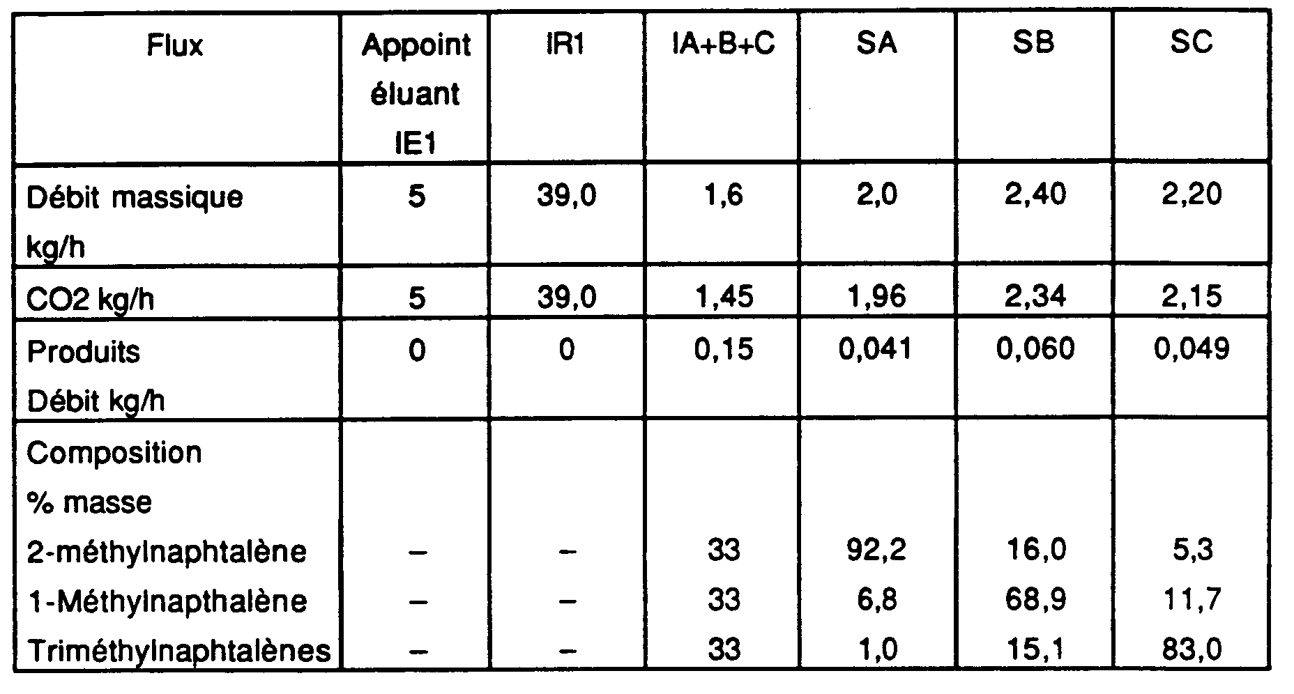
- Two-state solvent regime (solvent 〈〈fort〉〉, solvent 〈〈weak〉〉 within the meaning of patent FR-2 651 149)
- Number of columns or sections per zone: 3;
- Regime: quasi-isothermal around 40 ° C;
- Offset period: 10 minutes;
- Pressure in zone 0 (strong solvent): 253 bar; Density of the eluent: 900 kg.m -3 ;
- Pressure in zones I, II, III and IV (weak solvent): 146 bar Density of the eluent: 750 kg.m -3
- Flow rates and compositions of inputs / outputs:
- Régime à modulation de pression conforme à la présente invention ;
- Régime quasi-isotherme au voisinage de 40°C :
- Période de décalage : 8 minutes ;
- Caractéristiques des zones :
- Zone 0 : 3 colonnes de pression 212 bars : masse volumique du solvant : 850 kg.m-3 ;
- Zone I : 3 colonnes ; pression 146 bars ; masse volumique du solvant : 780 kg.m-3
- Zone II : 3 colonnes ; pression 146 bars ; masse volumique du solvant : 750 kg.m-3
- Zone III : 3 colonnes ; pression 131 bars, masse volumique du solvant : 710 kg.m-3
- Zone IV : 3 colonnes ; pression 128 bars : masse volumique du solvant : 700 kg.m-3
- Débits et compositions entre entrées/sorties :
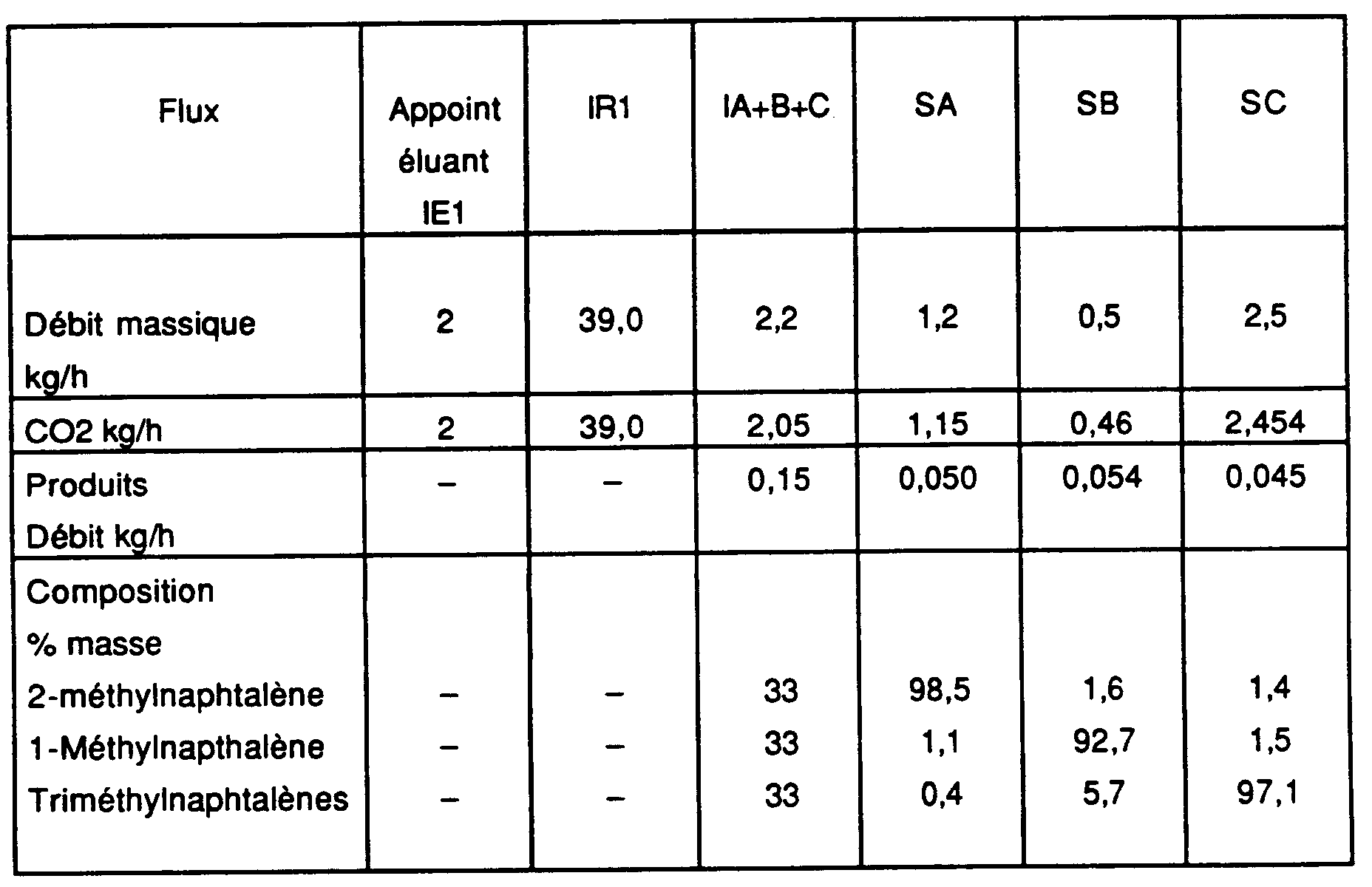
- Pressure modulation regime according to the present invention;
- Quasi-isothermal regime around 40 ° C:
- Offset period: 8 minutes;
- Zone characteristics:
- Zone 0: 3 pressure columns 212 bars: density of the solvent: 850 kg.m -3 ;
- Zone I: 3 columns; pressure 146 bars; solvent density: 780 kg.m -3
- Zone II: 3 columns; pressure 146 bars; solvent density: 750 kg.m -3
- Zone III: 3 columns; pressure 131 bars, density of the solvent: 710 kg.m -3
- Zone IV: 3 columns; pressure 128 bars: density of the solvent: 700 kg.m -3
- Flow rates and compositions between inputs / outputs:
On constate que les performances sont nettement supérieures dans le cas de la modulation de pression par rapport à celles obtenues dans l'autre cas (4a).It can be seen that the performances are clearly superior in the case of pressure modulation compared to those obtained in the other case (4a).
Le mélange à fractionner est constitué de 2,5-bromothiophène (33 % en masse), de 3,4 dibromothiophène (33 % en masse) et de 2,3,4,5-tétrabromothiophène (33 % en masse).The mixture to be fractionated consists of 2,5-bromothiophene (33% by mass), 3.4 dibromothiophene (33% by mass) and 2,3,4,5-tetrabromothiophene (33% by mass).
L'appareil est identique à celui utilisé dans l'exemple précédent et à l'exemple 1 (figure 3).The device is identical to the one used in the previous example and in Example 1 (Figure 3).
L'éluant utilisé est le trifluorobrométhane (CF3Br) dont les coordonnées critiques sont 39,7 bar et 67°C. Plusieurs modes de fonctionnement de l'appareillage et selon le procédé faisant l'objet de l'invention ont été mis en oeuvre selon le régime à pression sensiblement constante dans les cinq zones voisines de 70 bar, (température égale à 80°C) d'une part, et d'autre part selon le régime à modulation de pression décrit dans la présente demande.The eluent used is trifluorobromethane (CF 3 Br) whose critical coordinates are 39.7 bar and 67 ° C. Several operating modes of the apparatus and according to the method forming the subject of the invention were implemented according to the regime at substantially constant pressure in the five zones close to 70 bar, (temperature equal to 80 ° C) d 'on the one hand, and on the other hand according to the pressure modulation regime described in the present application.
Dans les exemples ci-dessous, les zones comprenant les nombres de colonnes suivants : zone 0 : une : zone I : trois : zone II : cinq : zone III : cinq : zone IV : une. La période de décalage est fixée à 3,3 minutes dans tous les cas.In the examples below, the areas comprising the following number of columns: zone 0: one: zone I: three: zone II: five: zone III: five: zone IV: one. The lag period is set at 3.3 minutes in all cases.
Les paramètres opératoires et les résultats obtenus sont les suivants :
- Régime à pression sensiblement constante (70 bars), température constante (80°C), masse volumique de l'éluant constante (1050 kg.m-3) ;
- La perte de charge dans les colonnes ou tronçons est faible et de plus le régime peut être considéré comme isotherme ;
- Débits et concentrations des entrées/sorties :

- Regime at substantially constant pressure (70 bars), constant temperature (80 ° C), constant density of the eluent (1050 kg.m -3 );
- The pressure drop in the columns or sections is low and moreover the regime can be considered as isothermal;
- Flow rates and concentrations of inputs / outputs:
Les paramètres opératoires et les résultats obtenus sont les suivants :
- Régime à modulation de pression de l'éluant, isotherme à 80°C ;
- Zone 0 : pression 100 bar; masse volumique de l'éluant: 1280 kg.m-3;
- Zone I : pression 81 bar ; masse volumique de l'éluant : 1150 kg.m-3
- Zone II : pression 76 bar ; masse volumique de l'éluant : 1100 kg.m-3
- Zone III : pression 68 bar, masse volumique de l'éluant : 950 kg.m-3
- Zone IV : pression 64 bar ; masse volumique de l'éluant: 900 kg.m-3
- Débits et compositions entre entrées/sorties :
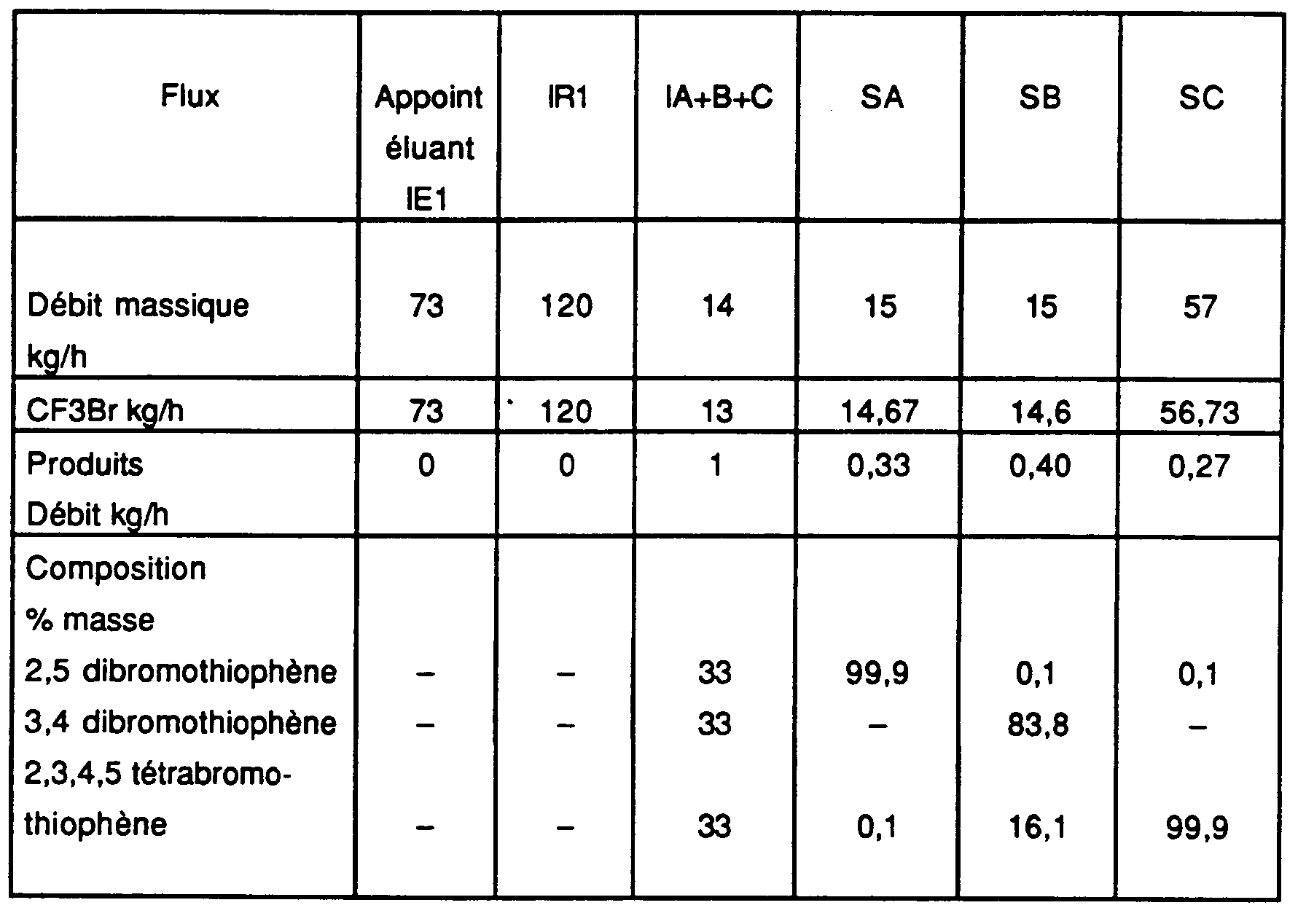
- Pressure modulating regime of the eluent, isothermal at 80 ° C;
- Zone 0: pressure 100 bar; density of the eluent: 1280 kg.m -3 ;
- Zone I: pressure 81 bar; density of the eluent: 1150 kg.m -3
- Zone II: pressure 76 bar; density of the eluent: 1100 kg.m -3
- Zone III: pressure 68 bar, density of the eluent: 950 kg.m -3
- Zone IV: pressure 64 bar; density of the eluent: 900 kg.m -3
- Flow rates and compositions between inputs / outputs:
On constate que le régime à modulation de pression conduit à des fractions nettement plus pures que celles de l'autre régime, le débit de solvant et le débit de charge traité restant les mêmes.It can be seen that the pressure modulation regime leads to fractions distinctly purer than those of the other regime, the flow rate of solvent and the treated feed rate remaining the same.
De plus, l'expérience a montré que quand on travaille avec un dispositif tel celui de la figure 3B on obtient des résultats quantitatifs et qualitatifs très voisins de ceux obtenus aux exemples 4b et 5b ci-dessus.In addition, experience has shown that when working with a device such as that of FIG. 3B, quantitative results are obtained and qualitative very similar to those obtained in Examples 4b and 5b above.
De même, avec l'appareillage de la figure 3A, les résultats quantitatifs et qualitatifs sont très voisins de ceux obtenus selon la figure 1.Likewise, with the apparatus of FIG. 3A, the results quantitative and qualitative are very similar to those obtained according to Figure 1.
Mais dans ces cas (mise en oeuvre des appareillages des figures 3A et 3B), les appareillages et leur utilisation sont simplifiés de façon appréciable.But in these cases (implementation of the switchgear of figures 3A and 3B), the equipment and their use are simplified in a way appreciable.
Pour illustrer de façon plus détailée les dispositifs conformes à l'invention, on se reportera à la figure 5 représentant schématiquement le montage de deux zones, colonnes ou tronçons de colonnes Ck et Ck+1. To illustrate in more detail the devices in accordance with the invention, reference is made to FIG. 5 which diagrammatically shows the assembly of two zones, columns or sections of columns C k and C k + 1 .
On retrouvera ici les éléments de la figure 2.We will find here the elements of figure 2.
Entre chaque paire de zones, de tronçons ou de colonnes Ck et Ck+1, on dispose deux vannes dont l'une est à passage total/fermeture totale (tout ou rien) dénommée Vk et une vanne de régulation permettant de réaliser la baisse de pression ou la détente souhaitée, dénommée Uk, de plus, deux vannes à passage total/fermeture totale (tout ou rien) sont connectées aux deux lignes d'aspiration SR et de refoulement IR du compresseur K (ou de la pompe éventuelle) et sont dénommées V'k et V''k. Avec ce système simple, on peut donc moduler les pressions dans toutes les colonnes de l'appareil, et en particulier déplacer les différentes zones susnommées afin de réaliser la mise en oeuvre du procédé objet de l'invention.Between each pair of zones, sections or columns C k and C k + 1, there are two valves, one of which is full flow / total closure (all or nothing) called V k and a control valve to achieve the desired drop in pressure or expansion, called U k , in addition, two full flow / full closure valves (all or nothing) are connected to the two SR suction and IR discharge lines of compressor K (or of the pump possible) and are called V ' k and V'' k . With this simple system, it is therefore possible to modulate the pressures in all the columns of the apparatus, and in particular to move the various aforementioned zones in order to carry out the implementation of the method which is the subject of the invention.
A cette disposition, on ajoute les éléments suivants qui
permettent notamment l'alimentation d'une partie de l'éluant (entre zones 0
et I de la figure 2 par exemple) en utilisant, dans le dispositif schématisé sur
la figure 5, les vannes à ouverture/fermeture totale ( 〈〈tout ou rien 〉〉) V''' et la
vanne de régulation U : ladite vanne U permet de détendre le fluide à la
pression d'entrée dans la zone I (ligne notée IR2) et peut avantageusement
être manoeuvrée par régulation du débit dans cette branche de circuit ;
lesdites vannes V''' sont manoeuvrées dans les mêmes conditions que les
vannes V'k. Si l'opérateur ne souhaite pas utiliser ce recyclage entre zones
(0 et I, figures 1 à 4), il peut fermer à la fois la vanne U et l'ensemble des
vannes V''', la totalité du fluide éluant étant alors distribuée par la ligne
notée IR1.To this arrangement, the following elements are added which
in particular allow the supply of part of the eluent (between
En ce qui concerne la variante avec pompe P et séparateur S, afin d'alimenter cette pompe, on condense le solvant dans un échangeur de chaleur et on le stocke dans un réservoir intermédiaire qui permet d'obtenir un pompage plus régulier ; le fluide comprimé issu de la pompe est ensuite porté à la température de travail grâce à un échangeur de chaleur. Le système est classiquement utilisé en extraction/fractionnement par fluide supercritique et n'a pas été représenté sur les figures.For the variant with P pump and S separator, in order to supply this pump, the solvent is condensed in a heat exchanger heat and it is stored in an intermediate tank which makes it possible to obtain more regular pumping; the compressed fluid from the pump is then brought to working temperature thanks to a heat exchanger. the system is conventionally used in fluid extraction / fractionation supercritical and has not been shown in the figures.
Claims (16)
- An apparatus for fractionating a mixture of p components into p components or q cuts, q being less than or equal to p, the apparatus comprising an assembly of n chromatographic columns or column sections mounted in series in a closed loop, having at least r injection stream and having q removal streams and at most n removal points per removal streams and at most n removal points per removal stream, the injection and removal points of different streams being advantageously identical, the injection and removal streams being alternated along the series of columns or sections, r, n, p and q being whole numbers defined as follows:
- p :
- represents the number of components present in the batch, p ≥ 2 ;
- q :
- represents the number of distinct cuts or effluents issuing from the process, q ≥ 2 ;
- n :
- represents the number of distinct columns or column sections used : n ≥ 3 ;
- r :
- represents the number of distinct injection streams in the
apparatus, and preferably q ≥ r ≥ 2 ;
the closed loop being formed of m successive chromatographic zones, such as (I, II, III ; I, II, III, IV ; O, I, II, III, IV ; I, Z, II, III, IV; I, II, III, Z, IV), each of these zones being constituted by at least one column or section (Ck) ; - m :
- represents the number of zones :
- Apparatus according to the claim 1 comprising three successive zones I, II, III for separation of two components or two cuts, wherein zone III (upstream of which mixture A+B is injected) is immediately followed by a release and separation means for the eluent and raffinate, the release and separation means comprising the raffinate removal point and the removal point for eluent recycling (SR) which is connected to the compressor or pump, allowing zone IV to be removed.
- Apparatus according to any one of claims 1 to 2 wherein a zone Z is interposed between zones I and II and is defined upstream by the extract removal point (SB) and downstream by a reinjection point (IRB) for a portion of the substantially eluent free extract.
- Apparatus according to any one of claims 1 to 2 wherein a zone Z is inserted downstream of zone III and is defined upstream by a reinjection point (IRA) for a substantially eluent free raffinate portion and downstream by the raffinate removal point (SA).
- Apparatus according to claim 1 wherein, comprising four zones (O, I, II, III) or five zones (O, I, II, III and IV), at least one additional pressure reduction or release means, connected to said control apparatus for periodic displacement, is situated between the zone O and the zone I.
- Apparatus according to claim 1, comprising four successive zones O, I, II, III for separation of three components A, B, C or three cuts, wherein zone III (downstream of the injection point for the mixture
- A process for fractionating a mixture of p components into p components or q cuts, q being less than or equal to p, using an apparatus comprising an assembly of n chromatographic columns or column sections mounted in series in a closed loop, having at least r injection streams and at most n injection points per injection stream and having q removal streams and at most n removal points per removal stream, the injection and removal points of different steams being advantageously identical, the injection and removal streams being alternated along the series of columns or sections, r, n, p and q being whole numbers defined as follows :
- p :
- represents the number of components present in the batch, p ≥ 2 ;
- q :
- represents the number of distinct cuts or effluents issuing from the process, q ≥ 2 ;
- n :
- represents the number of distinct columns or column sections used : n ≥ 3 ;
- r :
- represents the number of distinct injection streams in the
apparatus, and preferably q ≥ r ≥ 2 ;
the closed loop being formed of m successive chromatographic zones, such as (I, II, III ; I, II, III, IV ; O, I, II, III, IV; I, Z, II, III, IV; I, II, III, Z, IV), each of these zones being constituted by at least one column or section (Ck) ; - m :
- represents the number of zones :
the process being carried out so that, to separate a mixture of two components or two cuts, the pressure in one column (or zone) is maintained at a level which is higher than or equal to that in the column (or zone) immediately downstream except at each eluent injection point where the pressure increases to the injection pressure; and that to separate a mixture of three components or three cuts, the pressure is decreased by at least one interval between two removal points other than the extract removal point between zones O and I.or with injection of at least one supercritical fluid as eluent;or with injection of at least one subcritical fluid as eluent; - Process according to claim 7 wherein the pressure is decreased by at least one interval between two removal points following injection upstream of eluent (IR1) to the recycling removal point (SR).
- Process according to any one of claims 7 and 8 wherein the eluent fluid is injected into the closed loop at temperature different other than the operating temperatures.
- Process according to any one of claims 7 to 9 wherein the pressure is also decreased between zone O and zone I, for separating a mixture of three components or three cuts.
- Process according to any one of 7 to 10 wherein a mixture of three components is injected into an apparatus having four zones (O, I, II, III), wherein all the eluent and raffinate is released and separated downstream of zone III upstream of which the batch (
- Process according to any one of claims 7 and 9, wherein a mixture of two components is injected into an apparatus comprising three zones (I, II, III) wherein all the eluent and raffinate is released and separated downstream of zone III where mixture (AB) has been injected, the raffinate is collected and the eluent recycling stream is recycled at the injection pressure.
- Process according to any one of claims 7,9 and 12 wherein a portion of the substantially eluent free extract is introduced downstream of a zone Z between zone I and zone II, defined upstream by the extract removal point (SB) and downstream by a reinjection point (IRB) for said portion of the substantially eluent free extract.
- Process according to any one of claims 7, 9 and 12 wherein a portion of the substantially eluent free raffinate is introduced upstream of zone Z located downstream of zone III and defined upstream by a reinjection point (IRA) for said substantially eluent free raffinate portion and downstream by the raffinate removal point (SA).
- Process according to any one of claims 7 to 14, wherein the pressure in zone III is lower by at least one bar and preferably 3 to 100 bar than the pressure in zone II.
- Process according to any one of claims 7 to 15 wherein the pressure decreases between each zone from the zone receiving the eluent.
Applications Claiming Priority (7)
| Application Number | Priority Date | Filing Date | Title |
|---|---|---|---|
| FR9205304A FR2690630B1 (en) | 1992-04-29 | 1992-04-29 | PROCESS AND DEVICE FOR FRACTIONATING MIXTURES OF COMPONENTS BY CHROMATOGRAPHY USING AN ELUANT AT SUPERCRITICAL PRESSURE. |
| FR9205304 | 1992-04-29 | ||
| FR9209444 | 1992-07-30 | ||
| FR9209444A FR2694208B1 (en) | 1992-07-30 | 1992-07-30 | Industrial process and device for fractionation of mixtures of components by chromatography. |
| FR9304703 | 1993-04-21 | ||
| FR9304703A FR2704158B3 (en) | 1993-04-21 | 1993-04-21 | Method and device for fractionating a simulated moving bed mixture in the presence of a compressed gas. |
| PCT/FR1993/000419 WO1993022022A1 (en) | 1992-04-29 | 1993-04-28 | Method and device for fractionating a mixture in a simulated fluidized bed in the presence of a compressed gas, a supercritical fluid or a subcritical fluid |
Publications (2)
| Publication Number | Publication Date |
|---|---|
| EP0592646A1 EP0592646A1 (en) | 1994-04-20 |
| EP0592646B1 true EP0592646B1 (en) | 1999-02-03 |
Family
ID=27252600
Family Applications (1)
| Application Number | Title | Priority Date | Filing Date |
|---|---|---|---|
| EP93910080A Expired - Lifetime EP0592646B1 (en) | 1992-04-29 | 1993-04-28 | Method and device for chromatographically fractionating a mixture in a simulated mobile bed in the presence of a compressed gas, a supercritical fluid or a subcritical liquid |
Country Status (9)
| Country | Link |
|---|---|
| US (1) | US5422007A (en) |
| EP (1) | EP0592646B1 (en) |
| JP (1) | JPH07500771A (en) |
| CA (1) | CA2111084C (en) |
| DE (1) | DE69323382T2 (en) |
| DK (1) | DK0592646T3 (en) |
| ES (1) | ES2130262T3 (en) |
| NO (1) | NO303485B1 (en) |
| WO (1) | WO1993022022A1 (en) |
Families Citing this family (42)
| Publication number | Priority date | Publication date | Assignee | Title |
|---|---|---|---|---|
| US5770088A (en) * | 1992-06-30 | 1998-06-23 | Daicel Chemical Industries, Ltd. | Simulated moving bed chromatographic separation process |
| ES2097047T3 (en) * | 1993-04-29 | 1997-03-16 | Norsk Hydro As | PROCEDURES FOR THE CHROMATOGRAPHIC FRACTIONATION OF FATTY ACIDS AND THEIR DERIVATIVES. |
| FR2719233B1 (en) * | 1994-04-28 | 1996-07-19 | Inst Francais Du Petrole | Separation process in simulated moving bed at constant recycling rate. |
| EP0687491A1 (en) * | 1994-06-16 | 1995-12-20 | Daicel Chemical Industries, Ltd. | Simulated moving bed chromatographic separation process |
| CN1116088C (en) * | 1994-06-17 | 2003-07-30 | 代科化学工业株式会社 | Simulated moving bed chromatographic separation process |
| FR2721528B1 (en) | 1994-06-22 | 1996-09-06 | Inst Francais Du Petrole | Separation process by simulated moving bed chromatography with dead volume correction by desynchronization of the periods. |
| FR2721527B1 (en) | 1994-06-22 | 1996-09-06 | Inst Francais Du Petrole | Separation process by simulated moving bed chromatography with dead volume correction by increased flow. |
| FR2721529B1 (en) | 1994-06-22 | 1996-09-06 | Inst Francais Du Petrole | Separation process by simulated moving bed chromatography with dead volume correction by length reduction. |
| US5635072A (en) * | 1995-01-31 | 1997-06-03 | Uop | Simulated moving bed adsorptive separation process |
| FR2743002B1 (en) * | 1995-12-27 | 1998-01-30 | Inst Francais Du Petrole | PROCESS FOR REGULATING AT LEAST ONE FLUID FLOW CIRCULATING IN A CHROMATOGRAPHIC SEPARATION LOOP IN A SIMULATED MOBILE BED |
| FR2751888B1 (en) * | 1996-07-31 | 1998-09-11 | Inst Francais Du Petrole | DEVICE AND METHOD FOR RINSING A SIMULATED MOBILE BED COMPRISING AT LEAST TWO FLUID DELIVERY LINES |
| US6200390B1 (en) * | 1997-01-07 | 2001-03-13 | Amalgamated Research, Inc. | Simulated moving bed block displacement procedure |
| FR2766385B1 (en) * | 1997-07-24 | 1999-09-03 | Novasep | METHOD FOR CONTROLLING PRESSURE IN A SIMULATED MOBILE BED SEPARATION SYSTEM |
| FR2772634B1 (en) * | 1997-12-22 | 2000-02-18 | Inst Francais Du Petrole | METHOD AND DEVICE FOR IMPROVING THE PURITY OF A SIMULATED MOBILE BED PRODUCT |
| FR2781860B1 (en) * | 1998-07-31 | 2000-09-01 | Inst Francais Du Petrole | ALTERNATE COMMUNICATION SYSTEM OF AT LEAST FOUR FLUIDS AND ITS APPLICATION IN A SIMULATED MOBILE BED SEPARATION PROCESS |
| FR2790479B1 (en) * | 1999-03-02 | 2001-04-13 | Commissariat Energie Atomique | PROCESS FOR TREATING AN OIL USING A SUPERCRITICAL FLUID |
| DE19934168A1 (en) * | 1999-07-21 | 2001-01-25 | K D Pharma Bexbach Gmbh | Column chromatography separation process involves producing an eluant containing low. mol. wt. molecules using an apparatus including a pump, a separation column and a heat exchanger |
| FR2803538B1 (en) * | 1999-12-15 | 2002-06-07 | Separex Sa | METHOD AND DEVICE FOR CAPTURING FINE PARTICLES BY PERCOLATION IN A BED OF GRANULES |
| DE10051427C1 (en) * | 2000-10-17 | 2002-06-13 | Adam Mueller | Process for the production of an extract containing tetrahydrocannabinol and cannabidiol from cannabis plant material and cannabis extracts |
| DE10235385B4 (en) * | 2002-08-02 | 2006-10-05 | MAX-PLANCK-Gesellschaft zur Förderung der Wissenschaften e.V. | Method for the chromatographic separation of components |
| FR2846252B1 (en) * | 2002-10-29 | 2005-07-01 | Novasep | CHROMATOGRAPHY METHOD AND DEVICE INTEGRATING A CONCENTRATION STEP |
| FR2856313B1 (en) * | 2003-06-17 | 2005-07-29 | Inst Francais Du Petrole | METHOD FOR MANAGING THE VALVES OF A SIMUL MOBILE BED SEPARATION SYSTEM |
| DE102004000042B4 (en) * | 2004-11-16 | 2006-09-14 | Joint Analytical Systems Gmbh | Apparatus and method for determining material properties by means of HPLC |
| US20070051130A1 (en) * | 2005-09-06 | 2007-03-08 | Ming-Chi Chung | Supercritical fractionating apparatus and process |
| JP4940756B2 (en) * | 2006-05-22 | 2012-05-30 | ソニー株式会社 | Micro channel system |
| WO2008025887A1 (en) * | 2006-08-28 | 2008-03-06 | Novasep | Method for enriching one or more compounds of a mixture using a liquid mobile phase containing a gas |
| ES2459951T3 (en) | 2009-12-30 | 2014-05-13 | Basf Pharma (Callanish) Limited | Simulated mobile bed chromatographic separation process for the purification of polyunsaturated fatty acids |
| US8293111B2 (en) * | 2010-05-17 | 2012-10-23 | Uti Limited Partnership | Apparatus, system, and method for chromatography using a water stationary phase |
| GB201111595D0 (en) | 2011-07-06 | 2011-08-24 | Equateq Ltd | Improved process |
| GB201111589D0 (en) | 2011-07-06 | 2011-08-24 | Equateq Ltd | New modified process |
| GB201111594D0 (en) | 2011-07-06 | 2011-08-24 | Equateq Ltd | New improved process |
| GB201111601D0 (en) | 2011-07-06 | 2011-08-24 | Equateq Ltd | New process |
| GB201111591D0 (en) | 2011-07-06 | 2011-08-24 | Equateq Ltd | Further new process |
| GB201300354D0 (en) | 2013-01-09 | 2013-02-20 | Basf Pharma Callanish Ltd | Multi-step separation process |
| US8802880B1 (en) | 2013-05-07 | 2014-08-12 | Group Novasep | Chromatographic process for the production of highly purified polyunsaturated fatty acids |
| US9428711B2 (en) | 2013-05-07 | 2016-08-30 | Groupe Novasep | Chromatographic process for the production of highly purified polyunsaturated fatty acids |
| WO2014201222A1 (en) | 2013-06-14 | 2014-12-18 | Waters Technologies Corporation | Methodology for scaling methods between supercritical fluid chromatography systems |
| EP3118186B1 (en) | 2013-12-11 | 2022-02-09 | Novasep Process | Chromatographic facility for producing polyunsaturated fatty acids |
| JP6303017B2 (en) | 2014-01-07 | 2018-03-28 | ノヴァセプ プロセスNovasep Process | Method for purifying aromatic amino acids |
| WO2015175448A1 (en) * | 2014-05-12 | 2015-11-19 | Waters Technologies Corporation | Column temperature compensation for carbon dioxide based chromatographic system |
| CN108368434B (en) * | 2015-12-14 | 2021-05-11 | 沙特基础工业全球技术有限公司 | Method for separating aromatic hydrocarbons from a mixed hydrocarbon stream |
| CA3039158C (en) * | 2016-10-21 | 2023-09-26 | Novasep Process | Use of compressed gas for moving eluent applied to chromatography |
Family Cites Families (16)
| Publication number | Priority date | Publication date | Assignee | Title |
|---|---|---|---|---|
| US3761533A (en) * | 1970-07-23 | 1973-09-25 | Toray Industries | Separation process of components of feed mixture utilizing solid sorbent |
| US4500432A (en) * | 1981-07-13 | 1985-02-19 | Hewlett-Packard Company | Automated sample concentrator for trace components |
| FR2527934A1 (en) * | 1982-06-03 | 1983-12-09 | Elf Aquitaine | METHOD OF FRACTIONING BLENDS BY ELUTION CHROMATOGRAPHY WITH SUPERCRITICAL FLUID AND INSTALLATION FOR ITS IMPLEMENTATION |
| US4402832A (en) * | 1982-08-12 | 1983-09-06 | Uop Inc. | High efficiency continuous separation process |
| EP0127926B1 (en) * | 1983-06-03 | 1986-11-26 | Hewlett-Packard Company | Chromatographic separation |
| US4498991A (en) * | 1984-06-18 | 1985-02-12 | Uop Inc. | Serial flow continuous separation process |
| US5122275A (en) * | 1986-05-08 | 1992-06-16 | A. E. Staley Manufacturing Company | Simulated moving bed chromatographic separation |
| JPH0669521B2 (en) * | 1986-12-23 | 1994-09-07 | 三菱化成エンジニアリング株式会社 | Chromatographic separation method |
| US5180487A (en) * | 1987-09-25 | 1993-01-19 | Nihon Bunko Kogyo Kabushiki Kaisha | Pump apparatus for transferring a liquified gas used in a recycle chromatograph |
| JPH0746097B2 (en) * | 1988-05-17 | 1995-05-17 | 三菱化成エンジニアリング株式会社 | Chromatographic separation method |
| US5102553A (en) * | 1988-12-16 | 1992-04-07 | The Amalgamated Sugar Company | Time variable simulated moving bed process |
| US4990259A (en) * | 1988-12-16 | 1991-02-05 | The Amalgamated Sugar Company | Chromatographic separator sorbent bed preparation |
| FR2651149B1 (en) * | 1989-08-28 | 1992-06-05 | Inst Francais Du Petrole | CONTINUOUS PROCESS AND DEVICE FOR CHROMATOGRAPHIC SEPARATION OF A MIXTURE OF AT LEAST THREE CONSTITUENTS IN THREE PURIFIED EFFLUENTS USING A SINGLE SOLVENT AT TWO DIFFERENT TEMPERATURES AND / OR PRESSURES. |
| FR2651148B1 (en) * | 1989-08-28 | 1992-05-07 | Inst Francais Du Petrole | CONTINUOUS PROCESS AND DEVICE FOR CHROMATOGRAPHIC SEPARATION OF A MIXTURE OF AT LEAST THREE CONSTITUENTS IN THREE PURIFIED EFFLUENTS USING TWO SOLVENTS. |
| US5198120A (en) * | 1989-12-26 | 1993-03-30 | Japan Organo Co., Ltd. | Process for fractional separation of multi-component fluid mixture |
| US5156736A (en) * | 1991-05-07 | 1992-10-20 | Schoenrock Karlheinz W R | Simulated moving bed apparatus using a single sorbent bed for separating components from a fluid stream |
-
1993
- 1993-04-28 JP JP5519004A patent/JPH07500771A/en active Pending
- 1993-04-28 WO PCT/FR1993/000419 patent/WO1993022022A1/en active IP Right Grant
- 1993-04-28 EP EP93910080A patent/EP0592646B1/en not_active Expired - Lifetime
- 1993-04-28 DK DK93910080T patent/DK0592646T3/en active
- 1993-04-28 CA CA002111084A patent/CA2111084C/en not_active Expired - Lifetime
- 1993-04-28 DE DE69323382T patent/DE69323382T2/en not_active Expired - Lifetime
- 1993-04-28 US US08/170,248 patent/US5422007A/en not_active Expired - Lifetime
- 1993-04-28 ES ES93910080T patent/ES2130262T3/en not_active Expired - Lifetime
- 1993-12-27 NO NO934830A patent/NO303485B1/en not_active IP Right Cessation
Also Published As
| Publication number | Publication date |
|---|---|
| DK0592646T3 (en) | 1999-09-20 |
| JPH07500771A (en) | 1995-01-26 |
| CA2111084C (en) | 2004-07-06 |
| NO303485B1 (en) | 1998-07-20 |
| EP0592646A1 (en) | 1994-04-20 |
| NO934830L (en) | 1994-02-25 |
| CA2111084A1 (en) | 1993-11-11 |
| NO934830D0 (en) | 1993-12-27 |
| WO1993022022A1 (en) | 1993-11-11 |
| ES2130262T3 (en) | 1999-07-01 |
| DE69323382T2 (en) | 1999-06-10 |
| US5422007A (en) | 1995-06-06 |
| DE69323382D1 (en) | 1999-03-18 |
Similar Documents
| Publication | Publication Date | Title |
|---|---|---|
| EP0592646B1 (en) | Method and device for chromatographically fractionating a mixture in a simulated mobile bed in the presence of a compressed gas, a supercritical fluid or a subcritical liquid | |
| EP0099765B1 (en) | Process and plant for fractionating mixtures by elution chromatography with a supercritical fluid phase | |
| EP0415822B1 (en) | Continuous process and apparatus of chromatographic separation of a mixture of at least three components into three purified effluents by means of one solvent at two different temperatures and/or pressures | |
| EP1912716B1 (en) | Method and device for separating fractions of a mixture | |
| CA2348719C (en) | Separation method and device with chromatographic zones with variable length | |
| FI81268C (en) | KONTINUERLIGT SEPARATIONSFOERFARANDE BASERAT PAO SERIESTROEMNING. | |
| EP2276548B1 (en) | Gradient-elution multi-column separation method | |
| NO162701B (en) | PROCEDURE FOR AA SEPARATES AN EXTRA COMPONENT FROM A REFINATE COMPONENT INCLUDED IN A SUPPLY MIXTURE. | |
| FR2651148A1 (en) | CONTINUOUS PROCESS AND DEVICE FOR CHROMATOGRAPHIC SEPARATION OF A MIXTURE OF AT LEAST THREE CONSTITUENTS IN THREE EFFLUENTS PURIFIED BY TWO SOLVENTS. | |
| FR2935100A1 (en) | METHOD AND DEVICE FOR SEPARATING A MOBILE BED SIMULY AT A MODULE DERIVATION FLUID FLOW RATE | |
| FR2721529A1 (en) | Simulated moving bed chromatography separation method with dead volume correction by length reduction. | |
| EP0688589A1 (en) | Separation process by simulated moving bed chromatography with correction for dead volume by desynchronisation of periods | |
| FR2808270A1 (en) | Process for the co-production of meta xylene and para xylene uses a simulated mobile bed in a chromatographic column containing inter-connected solvent beds in a closed loop | |
| FR2460703A1 (en) | PROCESS FOR SEPARATING OR PURIFYING BLENDS USING AN ADSORBENT SOLID | |
| FR2721527A1 (en) | Separation method by simulated moving bed chromatography with correction of dead volume by flow rate increase. | |
| FR2690630A1 (en) | Complex chromatographic fractionation device | |
| EP0254610B1 (en) | Process for separating mixtures by extraction with the aid of supercritical fluid | |
| FR2704158A1 (en) | Process and device for fractionating a mixture in a simulated moving bed in the presence of a compressed gas. | |
| FR2694208A1 (en) | Complex chromatographic fractionation device | |
| FR2997396A1 (en) | METHOD AND DEVICE FOR THE PRODUCTION OF SIMULTANEOUS COUNTERCURRENT PARAXYLENE CONSISTING OF TWO ADSORBERS IN A TOTAL NUMBER OF BEDS BELOW OR EQUAL TO 22 | |
| CA3119417A1 (en) | Method and device for continuous countercurrent transfer of material between two fluid phases | |
| FR2794379A1 (en) | DEVICE FOR FRACTIONING SUPERCRITICAL PRESSURE MEMBRANE MIXTURES | |
| CA3039158C (en) | Use of compressed gas for moving eluent applied to chromatography | |
| EP3583988A1 (en) | Method and device for separation in a simulated mobile bed with a reduced number of beds with flow of bypass fluid | |
| BE565814A (en) |
Legal Events
| Date | Code | Title | Description |
|---|---|---|---|
| PUAI | Public reference made under article 153(3) epc to a published international application that has entered the european phase |
Free format text: ORIGINAL CODE: 0009012 |
|
| 17P | Request for examination filed |
Effective date: 19931214 |
|
| AK | Designated contracting states |
Kind code of ref document: A1 Designated state(s): BE CH DE DK ES FR GB IT LI NL SE |
|
| 17Q | First examination report despatched |
Effective date: 19951018 |
|
| GRAG | Despatch of communication of intention to grant |
Free format text: ORIGINAL CODE: EPIDOS AGRA |
|
| GRAG | Despatch of communication of intention to grant |
Free format text: ORIGINAL CODE: EPIDOS AGRA |
|
| GRAH | Despatch of communication of intention to grant a patent |
Free format text: ORIGINAL CODE: EPIDOS IGRA |
|
| GRAH | Despatch of communication of intention to grant a patent |
Free format text: ORIGINAL CODE: EPIDOS IGRA |
|
| GRAH | Despatch of communication of intention to grant a patent |
Free format text: ORIGINAL CODE: EPIDOS IGRA |
|
| GRAA | (expected) grant |
Free format text: ORIGINAL CODE: 0009210 |
|
| AK | Designated contracting states |
Kind code of ref document: B1 Designated state(s): BE CH DE DK ES FR GB IT LI NL SE |
|
| ITF | It: translation for a ep patent filed |
Owner name: DE DOMINICIS & MAYER S.R.L. |
|
| REG | Reference to a national code |
Ref country code: CH Ref legal event code: EP |
|
| GBT | Gb: translation of ep patent filed (gb section 77(6)(a)/1977) |
Effective date: 19990211 |
|
| REF | Corresponds to: |
Ref document number: 69323382 Country of ref document: DE Date of ref document: 19990318 |
|
| REG | Reference to a national code |
Ref country code: ES Ref legal event code: FG2A Ref document number: 2130262 Country of ref document: ES Kind code of ref document: T3 |
|
| REG | Reference to a national code |
Ref country code: DK Ref legal event code: T3 |
|
| PLBE | No opposition filed within time limit |
Free format text: ORIGINAL CODE: 0009261 |
|
| STAA | Information on the status of an ep patent application or granted ep patent |
Free format text: STATUS: NO OPPOSITION FILED WITHIN TIME LIMIT |
|
| 26N | No opposition filed | ||
| REG | Reference to a national code |
Ref country code: GB Ref legal event code: IF02 |
|
| REG | Reference to a national code |
Ref country code: FR Ref legal event code: CD |
|
| REG | Reference to a national code |
Ref country code: DE Ref legal event code: R081 Ref document number: 69323382 Country of ref document: DE Owner name: SEPAREX S.A., FR Free format text: FORMER OWNERS: INSTITUT FRANCAIS DU PETROLE, RUEIL-MALMAISON, HAUTS-DE-SEINE, FR; SEPAREX S.A., CHAMPIGNEULLES, FR Effective date: 20110329 Ref country code: DE Ref legal event code: R081 Ref document number: 69323382 Country of ref document: DE Owner name: IFP ENERGIES NOUVELLES, FR Free format text: FORMER OWNERS: INSTITUT FRANCAIS DU PETROLE, RUEIL-MALMAISON, HAUTS-DE-SEINE, FR; SEPAREX S.A., CHAMPIGNEULLES, FR Effective date: 20110329 Ref country code: DE Ref legal event code: R081 Ref document number: 69323382 Country of ref document: DE Owner name: SEPAREX S.A., FR Free format text: FORMER OWNER: INSTITUT FRANCAIS DU PETROLE, SEPAREX S.A., , FR Effective date: 20110329 Ref country code: DE Ref legal event code: R081 Ref document number: 69323382 Country of ref document: DE Owner name: IFP ENERGIES NOUVELLES, FR Free format text: FORMER OWNER: INSTITUT FRANCAIS DU PETROLE, SEPAREX S.A., , FR Effective date: 20110329 |
|
| PGFP | Annual fee paid to national office [announced via postgrant information from national office to epo] |
Ref country code: BE Payment date: 20120430 Year of fee payment: 20 Ref country code: DK Payment date: 20120425 Year of fee payment: 20 Ref country code: CH Payment date: 20120426 Year of fee payment: 20 Ref country code: DE Payment date: 20120509 Year of fee payment: 20 Ref country code: NL Payment date: 20120514 Year of fee payment: 20 |
|
| PGFP | Annual fee paid to national office [announced via postgrant information from national office to epo] |
Ref country code: SE Payment date: 20120425 Year of fee payment: 20 Ref country code: GB Payment date: 20120425 Year of fee payment: 20 Ref country code: FR Payment date: 20120423 Year of fee payment: 20 |
|
| PGFP | Annual fee paid to national office [announced via postgrant information from national office to epo] |
Ref country code: IT Payment date: 20120421 Year of fee payment: 20 |
|
| PGFP | Annual fee paid to national office [announced via postgrant information from national office to epo] |
Ref country code: ES Payment date: 20120420 Year of fee payment: 20 |
|
| REG | Reference to a national code |
Ref country code: DE Ref legal event code: R071 Ref document number: 69323382 Country of ref document: DE |
|
| REG | Reference to a national code |
Ref country code: DK Ref legal event code: EUP |
|
| BE20 | Be: patent expired |
Owner name: INSTITUT FRANCAIS DU *PETROLE Effective date: 20130428 Owner name: SOC. *SEPAREX Effective date: 20130428 |
|
| REG | Reference to a national code |
Ref country code: DE Ref legal event code: R071 Ref document number: 69323382 Country of ref document: DE Ref country code: CH Ref legal event code: PL |
|
| REG | Reference to a national code |
Ref country code: NL Ref legal event code: V4 Effective date: 20130428 |
|
| REG | Reference to a national code |
Ref country code: GB Ref legal event code: PE20 Expiry date: 20130427 |
|
| REG | Reference to a national code |
Ref country code: ES Ref legal event code: FD2A Effective date: 20130722 |
|
| PG25 | Lapsed in a contracting state [announced via postgrant information from national office to epo] |
Ref country code: GB Free format text: LAPSE BECAUSE OF EXPIRATION OF PROTECTION Effective date: 20130427 Ref country code: DE Free format text: LAPSE BECAUSE OF EXPIRATION OF PROTECTION Effective date: 20130430 |