EP2276548B1 - Gradientenelutionsmehrsäulentrennverfahren - Google Patents
Gradientenelutionsmehrsäulentrennverfahren Download PDFInfo
- Publication number
- EP2276548B1 EP2276548B1 EP09728317A EP09728317A EP2276548B1 EP 2276548 B1 EP2276548 B1 EP 2276548B1 EP 09728317 A EP09728317 A EP 09728317A EP 09728317 A EP09728317 A EP 09728317A EP 2276548 B1 EP2276548 B1 EP 2276548B1
- Authority
- EP
- European Patent Office
- Prior art keywords
- injection
- column
- mixture
- eluents
- columns
- Prior art date
- Legal status (The legal status is an assumption and is not a legal conclusion. Google has not performed a legal analysis and makes no representation as to the accuracy of the status listed.)
- Active
Links
- 238000000926 separation method Methods 0.000 title claims description 18
- 238000010828 elution Methods 0.000 title description 7
- 238000002347 injection Methods 0.000 claims description 121
- 239000007924 injection Substances 0.000 claims description 121
- 239000000203 mixture Substances 0.000 claims description 109
- 239000003480 eluent Substances 0.000 claims description 101
- 238000000034 method Methods 0.000 claims description 57
- 238000004587 chromatography analysis Methods 0.000 claims description 18
- 230000015572 biosynthetic process Effects 0.000 claims description 7
- 102000004169 proteins and genes Human genes 0.000 claims description 7
- 108090000623 proteins and genes Proteins 0.000 claims description 7
- 238000003786 synthesis reaction Methods 0.000 claims description 7
- 125000004122 cyclic group Chemical group 0.000 claims description 6
- 238000000855 fermentation Methods 0.000 claims description 6
- 230000004151 fermentation Effects 0.000 claims description 6
- 102000004196 processed proteins & peptides Human genes 0.000 claims description 6
- 108090000765 processed proteins & peptides Proteins 0.000 claims description 6
- 239000000284 extract Substances 0.000 claims description 4
- 108060003951 Immunoglobulin Proteins 0.000 claims description 3
- 102000018358 immunoglobulin Human genes 0.000 claims description 3
- 229940072221 immunoglobulins Drugs 0.000 claims description 3
- 230000000737 periodic effect Effects 0.000 claims description 3
- LFQSCWFLJHTTHZ-UHFFFAOYSA-N Ethanol Chemical compound CCO LFQSCWFLJHTTHZ-UHFFFAOYSA-N 0.000 description 38
- 239000000047 product Substances 0.000 description 37
- 239000012071 phase Substances 0.000 description 19
- 150000001875 compounds Chemical class 0.000 description 16
- 238000006073 displacement reaction Methods 0.000 description 11
- 239000012535 impurity Substances 0.000 description 11
- 230000014759 maintenance of location Effects 0.000 description 10
- 239000012530 fluid Substances 0.000 description 9
- 239000003607 modifier Substances 0.000 description 9
- 230000005526 G1 to G0 transition Effects 0.000 description 8
- 239000002904 solvent Substances 0.000 description 7
- 230000008929 regeneration Effects 0.000 description 6
- 238000011069 regeneration method Methods 0.000 description 6
- 238000002156 mixing Methods 0.000 description 5
- HTSGKJQDMSTCGS-UHFFFAOYSA-N 1,4-bis(4-chlorophenyl)-2-(4-methylphenyl)sulfonylbutane-1,4-dione Chemical compound C1=CC(C)=CC=C1S(=O)(=O)C(C(=O)C=1C=CC(Cl)=CC=1)CC(=O)C1=CC=C(Cl)C=C1 HTSGKJQDMSTCGS-UHFFFAOYSA-N 0.000 description 4
- 102400000243 Leu-enkephalin Human genes 0.000 description 4
- 108010022337 Leucine Enkephalin Proteins 0.000 description 4
- 239000006185 dispersion Substances 0.000 description 4
- URLZCHNOLZSCCA-UHFFFAOYSA-N leu-enkephalin Chemical compound C=1C=C(O)C=CC=1CC(N)C(=O)NCC(=O)NCC(=O)NC(C(=O)NC(CC(C)C)C(O)=O)CC1=CC=CC=C1 URLZCHNOLZSCCA-UHFFFAOYSA-N 0.000 description 4
- 239000007788 liquid Substances 0.000 description 4
- 239000002245 particle Substances 0.000 description 4
- 238000000746 purification Methods 0.000 description 4
- 239000003463 adsorbent Substances 0.000 description 3
- 238000010923 batch production Methods 0.000 description 3
- 238000004140 cleaning Methods 0.000 description 3
- 238000004088 simulation Methods 0.000 description 3
- 239000007787 solid Substances 0.000 description 3
- NLFBCYMMUAKCPC-KQQUZDAGSA-N ethyl (e)-3-[3-amino-2-cyano-1-[(e)-3-ethoxy-3-oxoprop-1-enyl]sulfanyl-3-oxoprop-1-enyl]sulfanylprop-2-enoate Chemical compound CCOC(=O)\C=C\SC(=C(C#N)C(N)=O)S\C=C\C(=O)OCC NLFBCYMMUAKCPC-KQQUZDAGSA-N 0.000 description 2
- 238000001033 granulometry Methods 0.000 description 2
- 239000013067 intermediate product Substances 0.000 description 2
- 239000003960 organic solvent Substances 0.000 description 2
- 230000000717 retained effect Effects 0.000 description 2
- 238000001179 sorption measurement Methods 0.000 description 2
- XLYOFNOQVPJJNP-UHFFFAOYSA-N water Substances O XLYOFNOQVPJJNP-UHFFFAOYSA-N 0.000 description 2
- 125000003088 (fluoren-9-ylmethoxy)carbonyl group Chemical group 0.000 description 1
- VYZAMTAEIAYCRO-UHFFFAOYSA-N Chromium Chemical compound [Cr] VYZAMTAEIAYCRO-UHFFFAOYSA-N 0.000 description 1
- 238000004458 analytical method Methods 0.000 description 1
- 230000006399 behavior Effects 0.000 description 1
- 239000007853 buffer solution Substances 0.000 description 1
- 238000004364 calculation method Methods 0.000 description 1
- 238000011109 contamination Methods 0.000 description 1
- 239000006184 cosolvent Substances 0.000 description 1
- 238000003795 desorption Methods 0.000 description 1
- 238000009826 distribution Methods 0.000 description 1
- 239000012149 elution buffer Substances 0.000 description 1
- 239000012156 elution solvent Substances 0.000 description 1
- 238000000605 extraction Methods 0.000 description 1
- 239000007789 gas Substances 0.000 description 1
- 238000009434 installation Methods 0.000 description 1
- 230000010354 integration Effects 0.000 description 1
- 239000003456 ion exchange resin Substances 0.000 description 1
- 229920003303 ion-exchange polymer Polymers 0.000 description 1
- 230000002045 lasting effect Effects 0.000 description 1
- 239000007791 liquid phase Substances 0.000 description 1
- 238000011068 loading method Methods 0.000 description 1
- 238000004519 manufacturing process Methods 0.000 description 1
- 230000005012 migration Effects 0.000 description 1
- 238000013508 migration Methods 0.000 description 1
- 238000010647 peptide synthesis reaction Methods 0.000 description 1
- 239000012264 purified product Substances 0.000 description 1
- 239000011347 resin Substances 0.000 description 1
- 229920005989 resin Polymers 0.000 description 1
- 230000002441 reversible effect Effects 0.000 description 1
- 150000003839 salts Chemical class 0.000 description 1
- 230000035945 sensitivity Effects 0.000 description 1
- 238000001542 size-exclusion chromatography Methods 0.000 description 1
- 239000007790 solid phase Substances 0.000 description 1
- 239000000243 solution Substances 0.000 description 1
- 239000004094 surface-active agent Substances 0.000 description 1
- 230000007704 transition Effects 0.000 description 1
Images


Classifications
-
- B—PERFORMING OPERATIONS; TRANSPORTING
- B01—PHYSICAL OR CHEMICAL PROCESSES OR APPARATUS IN GENERAL
- B01D—SEPARATION
- B01D15/00—Separating processes involving the treatment of liquids with solid sorbents; Apparatus therefor
- B01D15/08—Selective adsorption, e.g. chromatography
- B01D15/10—Selective adsorption, e.g. chromatography characterised by constructional or operational features
- B01D15/18—Selective adsorption, e.g. chromatography characterised by constructional or operational features relating to flow patterns
- B01D15/1864—Selective adsorption, e.g. chromatography characterised by constructional or operational features relating to flow patterns using two or more columns
Definitions
- the present invention relates to a method for separating multicolumns with gradient fractions of a mixture, by chromatography.
- Chromatography is a separation method based on the difference in the distribution of the compounds of a mixture between a mobile phase and a stationary phase, also called adsorbent phase.
- the compounds are separated by percolating a liquid, gaseous or supercritical solvent in a device (a column) filled with adsorbent phase.
- This method is widely used as an analytical technique to identify and quantify the compounds of a mixture. It can also be used as a purification technique.
- chromatographic methods are employed to perform the purification of molecules. These processes can be classified according to several criteria: the process can be discontinuous or continuous; systems can have one or more columns; the composition of the eluent can be isocratic, or a gradient can be made.
- Elution chromatography or batch chromatography is widely used. This process is based on the discontinuous injection of the mixture to be purified into a column filled with the appropriate stationary phase which is percolated with an eluent ensuring the migration and the separation of the products in the column. The separated products are withdrawn at the column outlet. The injections can be repeated periodically with a period of time to maintain the separation between successive injections.
- Batch chromatography is a widely used process, especially at small and medium scale. It is a simple process to implement (a single column) that is generally effective, but inefficient in terms of productivity. This is generally low and the purified products are generally very diluted in the elution solvent.
- the document EP-A-1,716,900 describes the integration of a motive force gradient method in an SMB method.
- the document describes a process for continuous purification or quasi-continuous of a mixture containing several compounds.
- the purification is carried out by means of at least two, preferably at least three individual chromatographic columns into which the mixture is introduced, by means of a solvent.
- the mixture containing several compounds comprises at least light impurities, an intermediate product to be purified and heavy impurities.
- the columns are used according to at least one step or a position in batch mode. In this mode the output of a column is used to withdraw the intermediate product.
- the columns are also used in at least one step or a position in continuous or quasi-continuous mode.
- the output of at least one column is fluidly connected to the input of at least one other column.
- the batch mode and the continuous or quasi-continuous mode are performed synchronously or sequentially. After or in a switching period, the columns are moved in a direction contrary to the general direction of the solvent flow.
- a disadvantage of this method is that it requires a complex device for its implementation and simulation tools for its understanding.
- the object of the invention is to obtain a powerful process while being simple to produce.
- the injection of the mixture to be separated is cyclic.
- the extraction of the enriched fraction is cyclic.
- the displacement of the injection points of the eluents is periodic.
- the eluents are injected continuously or discontinuously.
- At least one eluent is injected discontinuously.
- the composition of each eluent is constant.
- the composition of at least one eluent, independently of one another is variable.
- At least one eluent is moved asynchronously.
- At least two columns separate the injection point from the feed to be treated from the point of withdrawal of the product of interest, according to the direction of flow of the mobile phase.
- all the columns of the system separate the injection point from the charge to be treated from the point of withdrawal of the product of interest, according to the direction of flow of the mobile phase.
- the mixture to be separated is injected with the aid of members chosen from the group comprising an injection loop, an injection pump and a pressure vessel.
- the mixture to be separated is circulated in an additional chromatography column prior to injection into the device.
- the additional chromatography column is interposed between the mixing injection member and the single injection point of the mixture in the device or is between two columns of the device.
- the volume withdrawn from fraction enriched with the product of interest is variable.
- the mixture to be separated is injected with the aid of members selected from the group comprising an injection loop, an injection pump.
- the mixture to be separated is circulated in an additional chromatography column prior to injection into the device.
- the additional chromatography column is interposed between the mixing injection member and the single injection point of the mixture in the device or is between two columns of the device.
- composition of each eluent, independently of one another is constant or variable.
- the eluents are injected continuously or discontinuously.
- the eluents are moved independently of one another.
- the process is cyclic.
- the device constantly has at least one input and at least one output.
- the withdrawal of the product of interest is carried out at the outlet of the column preceding that at which the feed is introduced.
- the fraction depleted of the product of interest is reinjected into the device.
- a method of separating fractions of a mixture to be separated is applied to a device comprising at least two chromatography columns connected in series.
- the method comprises discontinuous injection steps of mixture to be separated, at a single point of the device, discontinuous withdrawal of the fraction enriched product of interest, at a single point of the device, injection of eluents in each column and moving elution injection points. These eluents have a different eluting force.
- the method allows an efficient separation and simple to achieve.
- This method is a gradient multicolumn separation method. This process is a non-batch process. It will apply in particular to the separations of a mixture containing at least two compounds.
- the separation proposed by the method uses an eluent force gradient applied during the chromatography.
- the molecules that can thus be purified are, for example: synthetic molecules, natural extracts, proteins obtained by fermentation, proteins obtained by synthesis or semisynthesis, immunoglobulins, monoclonal antibodies, peptides obtained by fermentation, peptides obtained by synthesis or hemi synthesis.
- the stationary phases that may be used are, for example: porous solid supports (for example silicas, also called normal phases), grafted porous solid supports (for example so-called reverse phases), ion exchange resins, grafted resins (for example by a protein). More generally, all the stationary phases for which it is relevant to apply a composition gradient of the mobile phase, for example size exclusion chromatography combined with the application of a gradient of surfactants.
- the gradient of composition of the mobile phase can be effected in different ways: passing from one composition to another in a direct manner, we speak then of 'step' gradient, or by a gradual transition from one composition to another .
- the figure 1 shows the operation of the separation process.
- This separation process is applied to a device comprising chromatography columns.
- This process makes it possible to separate fractions of a mixture (or charge) to be separated.
- the mixture may be binary or ternary, that is to say comprising two or three compounds.
- the product of interest is in the core fraction (i.e. the product of interest is framed by impurities who have lower and higher retention times).
- the mixture may contain more than three compounds.
- the device comprises three columns 1, 2 and 3 connected in series, that is to say that the column 1 has an outlet 12 contiguous to the inlet 21 of the column 2; this output 12 can be connected to the inlet 21 of the column 2, so as to circulate a fluid between the two columns 1 and 2.
- the outlet 22 of the column 2 is contiguous to the inlet 31 of the column 3.
- columns in series are called columns whose output of a first column may be connected to the input of a second column, to circulate a fluid between the two columns.
- the method operates in open loop, that is to say that at any time of the method, the device comprises at least one input and at least one output.
- Eluents A, B and C of different eluent forces are injected by the points 41, 42 and 43 respectively into the columns 1, 2 and 3, at points 11, 21 and 31.
- An outlet 4 is connected to the outlet 32 of the column 3.
- the injection points 41, 42, 43 of the eluents A, B and C are displaced.
- the period is the time between two trips of the same eluent.
- the injection points 41, 42, 43 are moved so that the eluents A, B and C are respectively injected in the columns 2, 3 and 1, at points 21, 31 and 11.
- the exit 4 which was located at exit 32 of the column 3 undergoes the same displacement and is then connected to the outlet 12 of the column 1.
- the injection points 41, 42 and 43 are displaced so that the eluents A, B and C are respectively injected in the columns 3, 1 and 2 at the points 31, 11 and 21, and the output 4 connected to the output 22 of the column 2.
- the composition of the mobile phase within the same column varies during a cycle, that is to say during the period after which an eluent injection point returns to its initial position.
- the column 3 will be crossed, in a cycle, successively by a mixture of the eluents A, B and C, then by a mixture of the eluents A and B, and finally by the only eluent A.
- the same situation is found for each column, successively.
- a composition gradient of the mobile phase within each column is created. This is advantageous, whether in terms of production (shorter cycles) or separation (better resolution between different products and reproducibility).
- Exit 4 presented on the figure 1 may be reinjected totally or partially at one of the eluent injection points 41, 42, or 43.
- each eluent takes place simultaneously, as an example. In this case, there are as many periods as there are columns.
- each eluent can be moved independently of the others (asynchronous moves), or not moved. These independent asynchronous movements take place periodically.
- Each of the eluents A, B and C may have an identical composition during one or more periods, or a cycle, or have a variable composition, independently of the other eluents. This is advantageous in that it is possible to adapt the eluent compositions according to the desired separation (separation rate, purity of the product of interest, etc.) and also according to the characteristics of the product of interest (sensitivity of retention times to the composition of the mobile phase). During the cycle it is possible that two eluents of different composition are injected simultaneously in the same column to achieve a particular input composition. This is advantageous in that it is possible to ensure multiple compositions at the inlet of a column from a few available initial compositions (fixed composition reservoirs).
- eluents A, B and C can be carried out discontinuously, or continuously, that is to say that the injection of the eluents is or not interrupted in time.
- a discontinuous injection has the advantage of great flexibility in allowing the eluent to be used for a sufficient duration.
- the injection of an eluent can be stopped when moving its injection point.
- a continuous injection has the advantage of simplicity of implementation.
- the mixture to be separated is injected at a single point of the device. According to figure 1 it is injected at the inlet 11 of the column 1, at the point of injection 61 of mixture.
- This injection point is unique. This is particularly advantageous in that it allows the use of all conventional injection devices as well as more complex devices. In addition, this prevents each column has an injection device. Thus, this device requires fewer ducts and valves, and is easier to clean. In addition, this device is easier to control than a device having multiple injection points of the mixture to be separated.
- injection loop can be used.
- This injection mode makes it possible to insert into the flow a known volume of the mixture to be separated. It is also possible to use a pump. This mode of injection makes it possible to inject the charge mixture to be treated directly, or in addition to an existing flow.
- the injection of the mixture to be separated is discontinuous (or in other words non-continuous), that is to say that the injection of the mixture is interrupted in time.
- This injection has the advantage of great flexibility and ease of implementation.
- the injection of the mixture to be separated is cyclic, during one of the periods or between two periods.
- the injection of mixture takes place during the period T3.
- the period T3 can thus comprise a sequence S1 during which the injection of mixture to be separated can occur. If the mixture is injected for a period less than the duration of the period T3, the sequence S1 may have a duration less than the period T3.
- the moment at which the mixture is injected and the column in which the mixture is injected is variable, the injection sequence depending on the case to take place during one or the other periods of the cycle, or even the Injection sequence can begin during one period and end in the next period.
- the withdrawal of the fraction enriched in product of interest is carried out at a single point of the device.
- the withdrawal is performed at the outlet 32 of the column 3. This is advantageous in that it requires the installation of only one withdrawal device for the entire device instead of a device per column.
- this device requires fewer ducts and valves, and is easier to clean. In addition, this device is easier to control.
- the withdrawal of the fraction enriched in the product of interest is carried out discontinuously, that is to say that the withdrawal is interrupted in time.
- This racking has the advantage of having great flexibility vis-à-vis the adjustment of the volume withdrawn. This makes it possible to adjust the concentration of the fraction, to remain within the physical limits of the system (solubility in the mobile phase, saturation of the stationary phase). The lower the volume withdrawn, the higher the concentration will be. In addition, the implementation of this racking is simpler than a continuous racking.
- the withdrawal of the fraction enriched in the product of interest is cyclical: it is carried out during one of the periods or can begin during one period and end in the next.
- the withdrawal can be total or partial (taking part of the flow passing from one column to the next).
- the withdrawal of the fraction enriched in the product of interest takes place during the period T3 at the point of withdrawal 62.
- the period T3 may thus comprise a sequence S1 during which the withdrawal of the fraction enriched in product of interest may occur. If the fraction enriched in the product of interest is withdrawn for a duration less than the duration of the period T3, the sequence S1 may have a duration less than the period T3.
- the figure 1 shows by way of example that withdrawal at the point of withdrawal 62 and injection of mixture at the injection point 61 can occur during the same sequence S1; however, injection and withdrawal may occur at different sequences.
- the withdrawal of the fraction product of interest can extend beyond the sequence S1, into a sequence S2 during which the mixture is no longer injected.
- figure 1 shows by way of example that the period T3 is longer than the sequences S1 and S2. The period T3 may thus comprise a sequence S3 during which neither the withdrawal of the fraction enriched in the product of interest nor the injection of mixture takes place.
- the withdrawal of the product of interest is carried out at the outlet of the last column. This is particularly advantageous in that the product of interest is withdrawn after it has passed through all the columns of the system.
- the injection of the mixture to be separated and the withdrawal of the product of interest can be carried out at the same time.
- the withdrawal of the product of interest during a cycle starts simultaneously with a new injection of the mixture to be separated.
- This particular case is however non-limiting of the invention.
- the figure 2 shows an example of operation of the separation method using two columns. This method is applied to a device comprising two columns in series. According to figure 2 during the first period T1 of the cycle two eluents of different eluting force are injected into the columns 1 and 2.
- the T1 period can be divided into 2 sequences.
- the first sequence S1 comprises the injection of two eluents A and B in the columns 1 and 2 respectively, at the injection points 41 and 42.
- the second sequence S2 comprises the injection of two eluents A and C in the columns 1 and 2 respectively, at injection points 41 and 43.
- the period T2 also comprises two sequences S1 and S2.
- the injection points of the eluents are displaced so that the two eluents A and B are respectively injected into the columns 2 and 1 during the sequence S1 (injection points 41 and 42) and that the eluents A and C are respectively injected in columns 2 and 1 during sequence S2 (injection points 41 and 43).
- the output of column 2 is connected to the input of column 1 during this second period T2.
- the cycle consists of two periods. Sequences (not shown) of injection of the mixture to be separated and withdrawn from the product of interest take place once during the cycle.
- the mixture can be injected at the inlet of column 2 during the sequence S1 of the period T2 and the product of interest can be withdrawn at the outlet of column 1 during the sequences S1 and S2 of the period T2.
- This example is not exhaustive on the events and the number of sequences of the periods.
- the Figures 3 and 4 show mixing injection devices. These devices use pumps 13 and 14 and an additional column 5.
- the additional column 5 is also called pre-column.
- the mixture is circulated in the additional column 5 before reaching the device.
- Such additional column 5 is intended to retain certain impurities of the mixture to be separated, in particular the impurities very strongly retained on the column. Thus, it makes it possible to limit the contamination of the device by certain impurities, and thus facilitates its cleaning.
- the figure 3 shows a mixture injection device in which the additional column 5 is inserted between the outlet of a first column and the inlet of a second column, these two columns being connected in series.
- the additional column 5 can be inserted between the outlet 32 of the column 3 and the inlet 11 of the column 1.
- Two three-way valves 6 and 7 are placed at the input and at the output of the additional column 5, and allow the connection between the columns in series and the additional column 5.
- the inlet valve 6 also makes it possible to inject the mixture to be separated 8, or else a regeneration solvent 9, in order to clean the additional column 5.
- the valve placed at the outlet 7 allows also to disconnect the output of the additional column 5 of the inlet of the next column to evacuate through line 10 the regeneration solvent 9 and the impurities to be evacuated. This is particularly advantageous in that only the additional column 5 and not the entire device should be regenerated. Another advantage is that the extra column can be cleaned without contaminating the device. A cleaning sequence, regeneration can take place during the cycle.
- the figure 4 shows a mixture injection device in which the additional column 5, or pre-column, is not inserted directly between the outlet of a first column and the inlet of a second column in series with the first, but in a set of ducts and three-way valves (17, 18, 19, 20) allowing different combinations: the mixture to be separated 8 can be inserted directly at the inlet of a column, or after circulation by the additional column 5.
- the column additional 5 can be disconnected from the inlet of a column and be regenerated without contaminating the device, nor stop the process by a regeneration step of the additional column 5.
- the additional column 5 can be connected to the outlet 32 of the column 3 by the valve 19 and the inlet 11 of the column 1 by the valve 20. Also, it can be seen that the additional column 5 can be short-circuited when the valves 19 and 20 are connected directly to each other.
- inventions 3 and 4 show by way of example two ways of using an additional column 5 to perform the injection of the load, devices using a different number of valves to 2 or more pump paths and solvents are naturally conceivable. Similarly, the flow direction of the fluids in the additional column can be reversed with respect to Figures 3 and 4 .
- the charge to be treated can also be injected into the system using not a pump but a pressurized container.
- the other fractions of the feed to be treated are withdrawn via a periodic displacement of a withdrawal line, or at a single point of the system. If desired, the withdrawal of the fractions is carried out on the total flow, or by a partial withdrawal.
- a regeneration sequence may also be added per period to regenerate the columns of the system.
- the process according to the invention is also applicable in cases of non-liquid elution, such as fluids containing CO 2 , described in the application WO-2008025887 , such as supercritical or subcritical fluids.
- non-liquid elution such as fluids containing CO 2
- WO-2008025887 such as supercritical or subcritical fluids.
- the addition of a co-solvent can then be performed.
- the columns may be of uniform or non-uniform volumes.
- the durations of the periods may be uniform or non-uniform.
- sequences of cleaning, desorption of strongly retained products, regeneration or balancing of the columns can be added, and can be of identical or different durations according to the periods. According to one variant, these steps can be performed by reversing the direction of elution.
- one or more unwanted product withdrawal sequences can be carried out punctually within the system. This racking makes it possible to avoid the excessive concentration of certain impurities whose retention times are close to the retention times of the desired product.
- the following example derived from a simulation, illustrates the implementation of the method compared to a batch process.
- the simulation exactly replicates the sequences described in the examples by repeating several cycles.
- the model used is diffusion-type piston with resistance to internal transfer, described by a law LDF (Linear Driving Force).
- LDF Linear Driving Force
- the parameters are extracted from the coefficients of a Van Deemter law, determined at a modifier concentration equal to that used for the definition of the parameters of the equilibrium law.
- the law of equilibrium of adsorption as well as the composition of the charge to be treated take again the model presented by Strohlein et al. (J.
- Chrom A 1126 (1-2), 338-346, 2006 ), considering a column 1 cm in diameter and 30 cm long, eluted at 1.6 mL / min, for a modifier content of 180 g / L, the retention times of the three compounds of the feed to be treated are respectively 127, 168 and 208.5 minutes; for a modifier content of 200 g / L, the retention times are 38.5, 49.5 and 60.5 minutes.
- the example uses the process according to figure 1 .
- the length and diameter of the columns is 10 cm and 1 cm respectively.
- Eluents A, B and C of different eluting force are injected by the points 41, 42 and 43 respectively in the columns 1, 2 and 3, at points 11, 21 and 31.
- the output 4 is connected to the output 32 of the column 3.
- the injection points 41, 42, 43 of the eluents A, B and C are displaced.
- the injection points 41, 42, 43 are displaced so that the eluents A, B and C are respectively injected in the columns 2, 3 and 1, at points 21, 31 and 11.
- the output 4 is then connected to exit 12 from column 1.
- the injection points 41, 42 and 43 are displaced so that the eluents A, B and C are respectively injected in the columns 3, 1 and 2 at the points 31, 11 and 21, and the output 4 connected to the output 22 of the column 2.
- the periods T1, T2 and T3 last 12.5 minutes.
- the cycle, lasting 37.5 minutes, begins at t 0.
- the T1 period ranges from 0 to 12.5 min.
- the T2 period ranges from 12.5 to 25 minutes.
- the period T3 ranges from 25 to 37.5 min.
- the period T3 can be divided into three sequences, as represented on the figure 1 .
- the first sequence S1 ranges from 25 to 26.5 minutes. During this period, 3.45 ml of mixture to be separated is injected at the inlet 11 of column 1. A withdrawal takes place at the outlet 32 of column 3.
- the second sequence S2 ranges from 26.5 to 27.1 minutes. There is no more injection of the mixture to be separated. The withdrawal at the outlet 32 of the column 3 is still effective.
- the third sequence S3 extends from 27.1 to 37.5 minutes. There is no more injection of the mixture to separate or withdrawal.
- the composition of the eluent A modifier varies linearly between 205 and 215 g / L between the beginning and the end of a period, so as to vary the eluent force of the eluent A.
- the content of the modifiers of the eluents B and C remains constant and equal to 180.7 and 172.8 g / L respectively.
- the flow rates of eluents A, B and C are 1.6, 0.8 and 1.4 ml / min respectively.
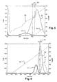
- the figure 5 shows the chromatogram obtained at the end of column 3.
- compound II is the compound of interest which it is desired to purify.
- Curve 51 corresponds to the concentration of compound I as a function of time.
- Curve 52 corresponds to the concentration of compound II as a function of time.
- Curve 53 corresponds to the concentration of compound III as a function of time.
- Curve 54 corresponds to the modifier concentration as a function of time.
- the interval 55 between the phantom lines delimits the time interval corresponding to the withdrawal.
- the purity is 96%, with a yield of 89%.
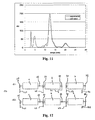
- the length and diameter of the column is 30 cm and 1 cm respectively.
- Compound II is the compound of interest which it is desired to purify.
- Curve 51 corresponds to the concentration of compound I as a function of time.
- Curve 52 corresponds to the concentration of compound II as a function of time.
- Curve 53 corresponds to the concentration of compound III as a function of time.
- Curve 54 corresponds to the modifier concentration as a function of time.
- the dot-dot lines 55 show the fraction drawn off with a purity of 94% and a yield of 20%.
- This example uses the conditions of Example 1 applied on two columns according to the figure 2 .
- the length and diameter of the columns are 10 cm and 1 cm respectively.
- the output of column 1 is connected to the input of column 2.
- eluents A and B are injected in columns 1 and 2 respectively.
- the eluents A and C are injected into the columns 1 and 2 respectively.
- the output of column 2 is connected to the input of column 1.
- eluents A and B are injected into columns 2 and 1 respectively.
- the eluents A and C are injected into the columns 2 and 1 respectively.
- the sequence S1 lasts 7.5 minutes, the sequence S2 lasts 17 minutes.
- the duration of a period is 24.5 minutes, the total duration of the cycle of 49 minutes.
- composition of eluent A is equal to 190 g / L of modifier 0 to 7.5 minutes and then varies linearly until reaching 200 g / L at the end of the period.
- composition of eluents B and C is constant and equal to 215 g / l and 127 g / l.
- the flow rates of eluents A, B and C are 2, 1.33 and 0.25 ml / min respectively.
- the injection of the mixture to be separated is carried out in column 1 between 38.5 and 39.5 min, with a flow rate of 2 ml / min.
- the product of interest is collected at the outlet of column 2 between 38.5 and 40.5 min.
- the purity obtained as the product of interest is 93% with a yield of 76%.
- the retention times of the peaks are reproduced from an equilibrium law of adsorption, the latter being the same as that used in the preceding examples.
- the parameters of the equilibrium law were calculated from experimental data.
- the elution rate is 0.5 ml / min.
- the leu-enkephalin retention times that were obtained are, respectively, 23.0 min, 12.4 min and 7.8 min.
- the retention times obtained made it possible to deduce the parameters of the equilibrium laws.
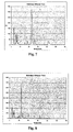
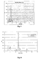
- This model reproduced representative behaviors of the leu-enkephalin peak as well as the nearest impurities.
- the figures 10 and 11 present the chromatogram obtained by using this model (dashed line), as well as the chromatogram obtained experimentally (solid line). This model is therefore usable for carrying out representative process calculations.
- a complete cycle (9.15 min) consists of three periods T1, T2 and T3.
- a period is defined by two sequences S1 and S2 of respective durations 0.775 and 2.275 min.
- the figure 12 schematizes the input and output lines during the first period T1.
- the duration of the T1, T2 and T3 periods is 3.05 min.
- the periods T2 and T3 are deduced from the first period T1 by switching the positions of the input and output lines of one and two columns respectively (cf. figure 13 ).
- the period T1 comprises 2 sequences S1 and S2.
- the first sequence S1 comprises the injection of three eluents A, B and D by the injection points 41, 42 and 43 in columns 1, 2 and 3 respectively, at points 11, 21 and 31.
- Outputs 51 and 52 are connected to the outputs 22 and 32 of the columns 2 and 3, respectively.
- the second sequence S2 comprises the injection of three eluents A, B and C by the injection points 41, 42 and 43 in columns 1, 2 and 3 respectively, at points 11, 21 and 31.
- An output 52 is connected. at the exit 32 of column 3.
- the output of column 2 is connected to the input of column 3 during this second sequence.
- the period T2 also includes two sequences S 1 and S 2.
- the injection points of the eluents are moved in such a way that the eluents A, B and D are respectively injected into the columns 2, 3 and 1 (injection points 41, 42 and 43) and that the outlets 51 and 52 are connected to the outputs 32 and 12 of the columns 3 and 1 during the sequence S 1 and that the eluants A, B and C are respectively injected in the columns 2, 3 and 1
- injection points 41, 42 and 43 injection points 41, 42 and 43 and that the output 52 is connected to the output 12 of the column 1 during the sequence S2.
- the output of column 3 is connected to the input of column 1 during this second sequence S2.
- the period T3 also comprises two sequences S1 and S2.
- the injection points of the eluents are moved in such a way that the eluents A, B and D are respectively injected into the columns 3, 1 and 2 (injection points 41, 42 and 43) and that the outlets 51 and 52 are connected to the outputs 12 and 22 of the columns 1 and 2 during the sequence S1 and that the eluents A, B and C are respectively injected in the columns 3, 1 and 2 (injection points 41, 42 and 43) and that the output 52 is connected to the output 22 of the column 2 during the sequence S2.
- the output of column 1 is connected to the input of column 2 during this second sequence S2.
- a sequence S0 (represented on the Figure 14 ) of the mixture to be separated and withdrawn from the product of interest takes place once during the cycle, at the beginning of the period T3.
- the collection of the product of interest and the injection of the mixture to be treated take place simultaneously for 0.5 min.
- the collection takes place at the outlet 32 of column 3 through the outlet 53 and the injection at the inlet 11 of column 1 by the injection point 42.
- the purities and yields thus obtained are then greater than 99%.
- a period is also defined by two sequences S1 and S2 (cf. figures 12 and 13 ) of respective durations 0.72 and 3.5 min.
- the duration of the period is 4.22 min.
- a sequence S0 (represented on the Figure 15 ) of injection of the mixture to be separated and withdrawn from the product of interest takes place once during the cycle, at the beginning of the period T2.
- the previous examples show that the process adapts to different raw charge profiles to be purified.
- the impurity profile of the M2 mixture has an impurity closer to the product of interest which explains slight differences in settings.
Landscapes
- Chemical & Material Sciences (AREA)
- Analytical Chemistry (AREA)
- Chemical Kinetics & Catalysis (AREA)
- Treatment Of Liquids With Adsorbents In General (AREA)
Claims (15)
- Verfahren zur Trennung von Fraktionen eines zu trennenden Gemischs, wobei das Verfahren die folgenden Schritte umfasst:- Bereitstellung einer Vorrichtung, die mindestens zwei Chromatographiesäulen umfasst, die in Reihe montiert sind,- diskontinuierliche Injektion des zu trennenden Gemischs in eine einzige Stelle der Vorrichtung,- diskontinuierliche Entnahme der mit einem Produkt von Interesse angereicherten Fraktion in eine einzige Stelle der Vorrichtung,- Injektion von Elutionsmitteln in jede Säule und Versetzung der Stellen der Injektion der Elutionsmittel, wobei die Elutionsmittel unterschiedliche Elutionskräfte aufweisen.
- Verfahren nach Anspruch 1, wobei die Injektion des zu trennenden Gemischs zyklisch ist.
- Verfahren nach einem der Ansprüche 1 oder 2, wobei die Entnahme der angereicherten Fraktion zyklisch ist.
- Verfahren nach Anspruch 3, wobei die Versetzung der Stellen der Injektion der Elutionsmittel periodisch ist.
- Verfahren nach einem der Ansprüche 1 bis 4, wobei die Elutionsmittel kontinuierlich oder diskontinuierlich injiziert werden.
- Verfahren nach einem der Ansprüche 1 bis 5, wobei mindestens ein Elutionsmittel diskontinuierlich injiziert wird.
- Verfahren nach einem der Ansprüche 1 bis 6, wobei die Zusammensetzung jedes Elutionsmittels konstant ist.
- Verfahren nach einem der Ansprüche 1 bis 7, wobei die Zusammensetzung mindestens eines Elutionsmittels unabhängig voneinander variabel ist.
- Verfahren nach einem der Ansprüche 1 bis 8, wobei mindestens ein Elutionsmittel asynchron versetzt wird.
- Verfahren nach einem der Ansprüche 1 bis 9, wobei mindestens zwei Säulen die Stelle der Injektion der zu behandelnden Beladung von der Stelle der Entnahme des Produkts von Interesse in Fließrichtung der mobilen Phase trennen.
- Verfahren nach einem der Ansprüche 1 bis 10, wobei alle Säulen des Systems die Stelle der Injektion der zu behandelnden Beladung von der Stelle der Entnahme des Produkts von Interesse in Fließrichtung der mobilen Phase trennen.
- Verfahren nach einem der Ansprüche 1 bis 11, wobei das zu trennende Gemisch mithilfe von Elementen injiziert wird, die aus der Gruppe ausgewählt ist, die eine Injektionsschleife, eine Injektionspumpe und einen Druckbehälter umfasst.
- Verfahren nach einem der Ansprüche 1 bis 12, wobei das zu trennende Gemisch vor der Injektion in die Vorrichtung in einer zusätzlichen Chromatographiesäule zirkuliert wird.
- Verfahren nach einem der Ansprüche 1 bis 13, wobei die zusätzliche Chromatographiesäule zwischen dem Element zur Injektion des Gemischs und der einzigen Stelle der Injektion des Gemischs in der Vorrichtung eingeschoben ist oder sich zwischen zwei Säulen der Vorrichtung befindet.
- Verwendung eines Verfahrens nach einem der Ansprüche 1 bis 14 zur Trennung von Synthesemolekülen, natürlichen Extrakten, durch Fermentation erhaltenen Proteinen, durch Synthese oder Semisynthese erhaltenen Proteinen, Immunglobulinen, monoklonalen Antikörpern, durch Fermentation erhaltenen Peptiden und durch Synthese oder Semisynthese erhaltenen Peptiden.
Applications Claiming Priority (2)
| Application Number | Priority Date | Filing Date | Title |
|---|---|---|---|
| FR0801844A FR2929533B1 (fr) | 2008-04-03 | 2008-04-03 | Procede de separation multicolonnes a gradient. |
| PCT/IB2009/005191 WO2009122281A1 (fr) | 2008-04-03 | 2009-04-03 | Procédé de séparation multicolonnes à gradient |
Publications (2)
| Publication Number | Publication Date |
|---|---|
| EP2276548A1 EP2276548A1 (de) | 2011-01-26 |
| EP2276548B1 true EP2276548B1 (de) | 2013-03-27 |
Family
ID=39874149
Family Applications (1)
| Application Number | Title | Priority Date | Filing Date |
|---|---|---|---|
| EP09728317A Active EP2276548B1 (de) | 2008-04-03 | 2009-04-03 | Gradientenelutionsmehrsäulentrennverfahren |
Country Status (6)
| Country | Link |
|---|---|
| US (1) | US8752417B2 (de) |
| EP (1) | EP2276548B1 (de) |
| JP (1) | JP5330499B2 (de) |
| CN (1) | CN102026695B (de) |
| FR (1) | FR2929533B1 (de) |
| WO (1) | WO2009122281A1 (de) |
Families Citing this family (52)
| Publication number | Priority date | Publication date | Assignee | Title |
|---|---|---|---|---|
| US8257948B1 (en) * | 2011-02-17 | 2012-09-04 | Purecircle Usa | Method of preparing alpha-glucosyl Stevia composition |
| US9386797B2 (en) | 2011-02-17 | 2016-07-12 | Purecircle Sdn Bhd | Glucosyl stevia composition |
| US9392799B2 (en) | 2011-02-17 | 2016-07-19 | Purecircle Sdn Bhd | Glucosyl stevia composition |
| US8790730B2 (en) | 2005-10-11 | 2014-07-29 | Purecircle Usa | Process for manufacturing a sweetener and use thereof |
| US8318459B2 (en) | 2011-02-17 | 2012-11-27 | Purecircle Usa | Glucosyl stevia composition |
| US9107436B2 (en) | 2011-02-17 | 2015-08-18 | Purecircle Sdn Bhd | Glucosylated steviol glycoside as a flavor modifier |
| WO2008150763A1 (en) * | 2007-05-29 | 2008-12-11 | Waters Investments Limited | Apparatus and methods for multidimensional analysis |
| BR112012011382B1 (pt) | 2009-11-12 | 2018-02-06 | Purecircle Usa Inc. | Método para produzir um adoçante e adoçante de stevia granulado |
| PT2519332E (pt) | 2009-12-30 | 2014-05-26 | Basf Pharma Callanish Ltd | Processo de separação cromatográfica em leito móvel simulado para a purificação de ácidos gordos poli-insaturados |
| US10696706B2 (en) | 2010-03-12 | 2020-06-30 | Purecircle Usa Inc. | Methods of preparing steviol glycosides and uses of the same |
| EP4108668A1 (de) | 2010-03-12 | 2022-12-28 | PureCircle USA Inc. | Hochreine steviol-glycoside |
| US9510611B2 (en) | 2010-12-13 | 2016-12-06 | Purecircle Sdn Bhd | Stevia composition to improve sweetness and flavor profile |
| BR112013014589B1 (pt) | 2010-12-13 | 2019-04-02 | Purecircle Usa Inc. | Método para preparar uma composição de rebaudiosídeo d altamente solúvel |
| BR112013020511B1 (pt) | 2011-02-10 | 2018-05-22 | Purecircle Usa Inc. | Composição de rebaudiosida b e seu processo de produção, bem como composições de adoçante e de sabor, ingrediente alimentício, bebida e produto cosmético ou farmacêutico compreendendo a dita composição de rebaudiosida b |
| US11690391B2 (en) | 2011-02-17 | 2023-07-04 | Purecircle Sdn Bhd | Glucosylated steviol glycoside as a flavor modifier |
| US9603373B2 (en) | 2011-02-17 | 2017-03-28 | Purecircle Sdn Bhd | Glucosyl stevia composition |
| US9474296B2 (en) | 2011-02-17 | 2016-10-25 | Purecircle Sdn Bhd | Glucosyl stevia composition |
| US9894922B2 (en) | 2011-05-18 | 2018-02-20 | Purecircle Sdn Bhd | Glucosyl rebaudioside C |
| PL2713763T3 (pl) | 2011-05-31 | 2019-10-31 | Purecircle Usa Inc | Kompozycja stewiowa |
| US9877501B2 (en) | 2011-06-03 | 2018-01-30 | Purecircle Sdn Bhd | Stevia composition |
| US9771434B2 (en) | 2011-06-23 | 2017-09-26 | Purecircle Sdn Bhd | Products from stevia rebaudiana |
| GB201111594D0 (en) | 2011-07-06 | 2011-08-24 | Equateq Ltd | New improved process |
| GB201111595D0 (en) | 2011-07-06 | 2011-08-24 | Equateq Ltd | Improved process |
| GB201111591D0 (en) | 2011-07-06 | 2011-08-24 | Equateq Ltd | Further new process |
| GB201111589D0 (en) | 2011-07-06 | 2011-08-24 | Equateq Ltd | New modified process |
| GB201111601D0 (en) | 2011-07-06 | 2011-08-24 | Equateq Ltd | New process |
| US10480019B2 (en) | 2011-08-10 | 2019-11-19 | Purecircle Sdn Bhd | Process for producing high-purity rubusoside |
| MX2014002462A (es) | 2011-09-07 | 2014-05-07 | Purecircle Usa Inc | Edulcorante de estevia altamente soluble. |
| EP2852296B1 (de) | 2012-05-22 | 2021-12-15 | PureCircle SDN BHD | Prozess zur produktion eines hochreinen stevio-glycosides |
| US9752174B2 (en) | 2013-05-28 | 2017-09-05 | Purecircle Sdn Bhd | High-purity steviol glycosides |
| GB201300354D0 (en) | 2013-01-09 | 2013-02-20 | Basf Pharma Callanish Ltd | Multi-step separation process |
| US8802880B1 (en) | 2013-05-07 | 2014-08-12 | Group Novasep | Chromatographic process for the production of highly purified polyunsaturated fatty acids |
| US9428711B2 (en) | 2013-05-07 | 2016-08-30 | Groupe Novasep | Chromatographic process for the production of highly purified polyunsaturated fatty acids |
| ES2817049T5 (es) | 2013-06-07 | 2023-11-10 | Purecircle Usa Inc | Extracto de estevia que contiene glucósidos de esteviol seleccionados como modificador del perfil de gusto, sabor y dulzor |
| US10952458B2 (en) | 2013-06-07 | 2021-03-23 | Purecircle Usa Inc | Stevia extract containing selected steviol glycosides as flavor, salty and sweetness profile modifier |
| EP2883860B1 (de) | 2013-12-11 | 2016-08-24 | Novasep Process | Chromatografisches Verfahren zur Herstellung von mehrfach ungesättigten Fettsäuren |
| JP6303017B2 (ja) | 2014-01-07 | 2018-03-28 | ノヴァセプ プロセスNovasep Process | 芳香族アミノ酸を精製する方法 |
| FR3018450B1 (fr) | 2014-03-11 | 2016-04-15 | Lab Francais Du Fractionnement | Procede de preparation de proteines plasmatiques humaines |
| WO2015140928A1 (ja) * | 2014-03-18 | 2015-09-24 | 三菱電機株式会社 | タッチパネル、入力装置、リモコン装置及びタッチパネルの製造方法 |
| CN107105686B (zh) | 2014-09-02 | 2021-12-24 | 谱赛科美国股份有限公司 | 富含莱鲍迪苷d、e、n和/或o的甜菊提取物及其制备方法 |
| US11216131B2 (en) | 2014-11-20 | 2022-01-04 | Dongwoo Fine-Chem Co., Ltd. | Film touch sensor and manufacturing method therefor |
| KR20160071735A (ko) | 2014-12-12 | 2016-06-22 | 동우 화인켐 주식회사 | 필름 터치 센서 및 그의 제조 방법 |
| RU2731068C2 (ru) | 2015-10-26 | 2020-08-28 | ПЬЮРСЁРКЛ ЮЭсЭй ИНК. | Стевиолгликозидные композиции |
| MX2018007241A (es) | 2015-12-15 | 2018-11-09 | Purecircle Usa Inc | Composiciones de glicosido de esteviol. |
| CN105597371B (zh) * | 2016-01-14 | 2017-10-20 | 中国科学院过程工程研究所 | 一种基于模拟移动床的连续梯度洗脱系统及其处理方法 |
| CN105892551B (zh) * | 2016-03-31 | 2018-03-16 | 华为技术有限公司 | 全局最大输出功率确定方法与装置 |
| WO2018007530A1 (en) | 2016-07-06 | 2018-01-11 | Laboratoire Francais Du Fractionnement Et Des Biotechnologies | Anti-fibrinogen aptamers and uses thereof |
| EP3491136A1 (de) | 2016-07-28 | 2019-06-05 | Laboratoire Francais du Fractionnement et des Biotechnologies Societe Anonyme | Aptamere gegen immunoglobulin g und verwendungen davon |
| GB201710130D0 (en) * | 2017-06-26 | 2017-08-09 | Ge Healthcare Bioprocess R & D Ab | A Method of seperation |
| FR3073424B1 (fr) * | 2017-11-16 | 2022-03-25 | Novasep Process | Procede regule de separation d’un melange |
| ES2943844T3 (es) * | 2018-11-16 | 2023-06-16 | Organo Corp | Método de separación cromatográfica usando una técnica de tipo lecho móvil simulado y sistema de separación cromatográfica usando una técnica de tipo lecho móvil simulado |
| GB201906279D0 (en) * | 2019-05-03 | 2019-06-19 | Nicoventures Trading Ltd | Electronic aerosol provision system |
Family Cites Families (10)
| Publication number | Priority date | Publication date | Assignee | Title |
|---|---|---|---|---|
| JPH02238358A (ja) * | 1989-03-13 | 1990-09-20 | Shimadzu Corp | 液体クロマトグラフの溶媒組成制御方法 |
| JPH07106281B2 (ja) * | 1991-01-16 | 1995-11-15 | 綜研化学株式会社 | 多成分混合物の分離精製方法及び装置 |
| US5630943A (en) * | 1995-11-30 | 1997-05-20 | Merck Patent Gesellschaft Mit Beschrankter Haftung | Discontinuous countercurrent chromatographic process and apparatus |
| US5762947A (en) * | 1997-05-09 | 1998-06-09 | Elizabeth Arden Co., Division Of Conopco, Inc. | Cosmetic skin conditioning compositions containing a salicyloxy α-carboxy acid |
| JP3675681B2 (ja) * | 1999-09-02 | 2005-07-27 | 株式会社サクション瓦斯機関製作所 | 容器移動装置およびクロマトグラフ装置 |
| JP4627841B2 (ja) * | 2000-06-08 | 2011-02-09 | 国立大学法人 香川大学 | プシコースの分離方法 |
| JP4652895B2 (ja) * | 2004-08-20 | 2011-03-16 | ダイセル化学工業株式会社 | クロマトグラフィー装置及び溶剤組成調整装置 |
| EP1716900A1 (de) * | 2005-04-29 | 2006-11-02 | Eidgenössische Technische Hochschule Zürich | Verfahren und Vorrichtung zur chromatographischen Reinigung |
| DE102005026486A1 (de) * | 2005-06-09 | 2006-12-14 | Bayer Technology Services Gmbh | Ein chromatographisches quasi-kontinuierliches Verfahren und entsprechende Vorrichtung zur Trennung von binären und Mehrstoffgemischen |
| FR2889077B1 (fr) * | 2005-07-26 | 2007-10-12 | Novasep Soc Par Actions Simpli | Procede et dispositif de separation chromatographique de fractions d'un melange |
-
2008
- 2008-04-03 FR FR0801844A patent/FR2929533B1/fr active Active
-
2009
- 2009-04-03 WO PCT/IB2009/005191 patent/WO2009122281A1/fr active Application Filing
- 2009-04-03 US US12/936,319 patent/US8752417B2/en active Active
- 2009-04-03 CN CN2009801175710A patent/CN102026695B/zh active Active
- 2009-04-03 JP JP2011502453A patent/JP5330499B2/ja active Active
- 2009-04-03 EP EP09728317A patent/EP2276548B1/de active Active
Also Published As
| Publication number | Publication date |
|---|---|
| WO2009122281A1 (fr) | 2009-10-08 |
| JP2011517489A (ja) | 2011-06-09 |
| US20110030457A1 (en) | 2011-02-10 |
| FR2929533B1 (fr) | 2010-04-30 |
| FR2929533A1 (fr) | 2009-10-09 |
| EP2276548A1 (de) | 2011-01-26 |
| US8752417B2 (en) | 2014-06-17 |
| JP5330499B2 (ja) | 2013-10-30 |
| CN102026695A (zh) | 2011-04-20 |
| CN102026695B (zh) | 2013-11-13 |
Similar Documents
| Publication | Publication Date | Title |
|---|---|---|
| EP2276548B1 (de) | Gradientenelutionsmehrsäulentrennverfahren | |
| EP1912716B1 (de) | Verfahren und vorrichtung zur trennung von fraktionen einer mischung | |
| EP0415822B1 (de) | Kontinuierliches Verfahren und Vorrichtung für eine chromatographische Trennung einer Mischung von mindestens drei Bestandteilen in drei gereinigte Ausflüsse mittels eines Lösungsmittels bei zwei verschiedenen Temperaturen und/oder Drucken | |
| EP1128881B1 (de) | Trennungsverfahren mit längenveränderlichen chromatographischen zonen | |
| EP0415821A1 (de) | Kontinuierliches Verfahren und Vorrichtung für eine chromatographische Trennung einer Mischung von mindestens drei Bestandteilen in drei gereinigte Ausflüsse mittels zwei Lösungsmitteln | |
| EP2024049B1 (de) | Verfahren zum trennen von fraktionen eines gemisches | |
| EP2040811A2 (de) | Verfahren zur sequentiellen mehrfachkolonnentrennung | |
| FR2656231A1 (fr) | Procede et equipement pour la separation fractionnaire chromatographique d'un fluide. | |
| FR2764822A1 (fr) | Methode pour optimiser le fonctionnement d'un systeme de separation des constituants d'un melange | |
| FR2925349A1 (fr) | Procede de separation sequence multicolonnes d'un derive metallique ionique | |
| EP2637760B1 (de) | Trennverfahren mittels kontinuierlicher chromatographie mit hohem durchfluss und entsprechende vorrichtung | |
| EP1101516A1 (de) | Verfahren zur Bestimmung optimaler Bedingungen der Stabilisierung eines Trennungssystems eines simulierten Wanderbettes durch Simulation | |
| FR2721527A1 (fr) | Procédé de séparation par chromatographie en lit mobile simulé avec correction de volume mort par augmentation de débit. | |
| FR2907686A1 (fr) | Dispositif et procede de chromatographie a contre courant vrai | |
| EP3583988B1 (de) | Abscheideverfahren und -vorrichtung im simulierten fliessbett mit einer geringen anzahl von fliessbetten mit ablenkungsflüssigkeitsdurchsatz | |
| CA3039158C (fr) | Utilisation de gaz comprime pour le deplacement d'eluant applique a la chromatographie | |
| EP3583989B1 (de) | Abscheideverfahren und -vorrichtung im simulierten fliessbett mit ablenkungsflüssigkeitsdurchsatz | |
| FR2690630A1 (fr) | Procédé et dispositif de fractionnement de mélanges de composants par voie chromatographique à l'aide d'un éluant à pression supercritique. | |
| WO2020099796A1 (fr) | Procédé et dispositif de transfert de matière en continu à contre-courant entre deux phases fluides | |
| EP1064065B1 (de) | Verfahren zur anreicherung optischer isomere in einem simulierten wanderbett | |
| FR2794379A1 (fr) | Dispositif de fractionnement de melanges a membrane operant a pression supercritique |
Legal Events
| Date | Code | Title | Description |
|---|---|---|---|
| PUAI | Public reference made under article 153(3) epc to a published international application that has entered the european phase |
Free format text: ORIGINAL CODE: 0009012 |
|
| 17P | Request for examination filed |
Effective date: 20101103 |
|
| AK | Designated contracting states |
Kind code of ref document: A1 Designated state(s): AT BE BG CH CY CZ DE DK EE ES FI FR GB GR HR HU IE IS IT LI LT LU LV MC MK MT NL NO PL PT RO SE SI SK TR |
|
| AX | Request for extension of the european patent |
Extension state: AL BA RS |
|
| DAX | Request for extension of the european patent (deleted) | ||
| GRAP | Despatch of communication of intention to grant a patent |
Free format text: ORIGINAL CODE: EPIDOSNIGR1 |
|
| GRAS | Grant fee paid |
Free format text: ORIGINAL CODE: EPIDOSNIGR3 |
|
| GRAA | (expected) grant |
Free format text: ORIGINAL CODE: 0009210 |
|
| AK | Designated contracting states |
Kind code of ref document: B1 Designated state(s): AT BE BG CH CY CZ DE DK EE ES FI FR GB GR HR HU IE IS IT LI LT LU LV MC MK MT NL NO PL PT RO SE SI SK TR |
|
| REG | Reference to a national code |
Ref country code: GB Ref legal event code: FG4D Free format text: NOT ENGLISH |
|
| REG | Reference to a national code |
Ref country code: CH Ref legal event code: EP |
|
| REG | Reference to a national code |
Ref country code: AT Ref legal event code: REF Ref document number: 602994 Country of ref document: AT Kind code of ref document: T Effective date: 20130415 |
|
| REG | Reference to a national code |
Ref country code: IE Ref legal event code: FG4D Free format text: LANGUAGE OF EP DOCUMENT: FRENCH |
|
| REG | Reference to a national code |
Ref country code: DE Ref legal event code: R096 Ref document number: 602009014382 Country of ref document: DE Effective date: 20130529 |
|
| REG | Reference to a national code |
Ref country code: CH Ref legal event code: NV Representative=s name: CABINET ROLAND NITHARDT CONSEILS EN PROPRIETE , CH |
|
| RAP2 | Party data changed (patent owner data changed or rights of a patent transferred) |
Owner name: NOVASEP PROCESS |
|
| PG25 | Lapsed in a contracting state [announced via postgrant information from national office to epo] |
Ref country code: SE Free format text: LAPSE BECAUSE OF FAILURE TO SUBMIT A TRANSLATION OF THE DESCRIPTION OR TO PAY THE FEE WITHIN THE PRESCRIBED TIME-LIMIT Effective date: 20130327 Ref country code: BG Free format text: LAPSE BECAUSE OF FAILURE TO SUBMIT A TRANSLATION OF THE DESCRIPTION OR TO PAY THE FEE WITHIN THE PRESCRIBED TIME-LIMIT Effective date: 20130627 Ref country code: LT Free format text: LAPSE BECAUSE OF FAILURE TO SUBMIT A TRANSLATION OF THE DESCRIPTION OR TO PAY THE FEE WITHIN THE PRESCRIBED TIME-LIMIT Effective date: 20130327 Ref country code: NO Free format text: LAPSE BECAUSE OF FAILURE TO SUBMIT A TRANSLATION OF THE DESCRIPTION OR TO PAY THE FEE WITHIN THE PRESCRIBED TIME-LIMIT Effective date: 20130627 |
|
| REG | Reference to a national code |
Ref country code: AT Ref legal event code: MK05 Ref document number: 602994 Country of ref document: AT Kind code of ref document: T Effective date: 20130327 |
|
| REG | Reference to a national code |
Ref country code: LT Ref legal event code: MG4D |
|
| PG25 | Lapsed in a contracting state [announced via postgrant information from national office to epo] |
Ref country code: FI Free format text: LAPSE BECAUSE OF FAILURE TO SUBMIT A TRANSLATION OF THE DESCRIPTION OR TO PAY THE FEE WITHIN THE PRESCRIBED TIME-LIMIT Effective date: 20130327 Ref country code: SI Free format text: LAPSE BECAUSE OF FAILURE TO SUBMIT A TRANSLATION OF THE DESCRIPTION OR TO PAY THE FEE WITHIN THE PRESCRIBED TIME-LIMIT Effective date: 20130327 Ref country code: GR Free format text: LAPSE BECAUSE OF FAILURE TO SUBMIT A TRANSLATION OF THE DESCRIPTION OR TO PAY THE FEE WITHIN THE PRESCRIBED TIME-LIMIT Effective date: 20130628 Ref country code: LV Free format text: LAPSE BECAUSE OF FAILURE TO SUBMIT A TRANSLATION OF THE DESCRIPTION OR TO PAY THE FEE WITHIN THE PRESCRIBED TIME-LIMIT Effective date: 20130327 |
|
| REG | Reference to a national code |
Ref country code: NL Ref legal event code: VDEP Effective date: 20130327 |
|
| PG25 | Lapsed in a contracting state [announced via postgrant information from national office to epo] |
Ref country code: HR Free format text: LAPSE BECAUSE OF FAILURE TO SUBMIT A TRANSLATION OF THE DESCRIPTION OR TO PAY THE FEE WITHIN THE PRESCRIBED TIME-LIMIT Effective date: 20130327 |
|
| BERE | Be: lapsed |
Owner name: NOVASEP Effective date: 20130430 |
|
| PG25 | Lapsed in a contracting state [announced via postgrant information from national office to epo] |
Ref country code: CZ Free format text: LAPSE BECAUSE OF FAILURE TO SUBMIT A TRANSLATION OF THE DESCRIPTION OR TO PAY THE FEE WITHIN THE PRESCRIBED TIME-LIMIT Effective date: 20130327 Ref country code: NL Free format text: LAPSE BECAUSE OF FAILURE TO SUBMIT A TRANSLATION OF THE DESCRIPTION OR TO PAY THE FEE WITHIN THE PRESCRIBED TIME-LIMIT Effective date: 20130327 Ref country code: AT Free format text: LAPSE BECAUSE OF FAILURE TO SUBMIT A TRANSLATION OF THE DESCRIPTION OR TO PAY THE FEE WITHIN THE PRESCRIBED TIME-LIMIT Effective date: 20130327 Ref country code: ES Free format text: LAPSE BECAUSE OF FAILURE TO SUBMIT A TRANSLATION OF THE DESCRIPTION OR TO PAY THE FEE WITHIN THE PRESCRIBED TIME-LIMIT Effective date: 20130708 Ref country code: SK Free format text: LAPSE BECAUSE OF FAILURE TO SUBMIT A TRANSLATION OF THE DESCRIPTION OR TO PAY THE FEE WITHIN THE PRESCRIBED TIME-LIMIT Effective date: 20130327 Ref country code: IS Free format text: LAPSE BECAUSE OF FAILURE TO SUBMIT A TRANSLATION OF THE DESCRIPTION OR TO PAY THE FEE WITHIN THE PRESCRIBED TIME-LIMIT Effective date: 20130727 Ref country code: EE Free format text: LAPSE BECAUSE OF FAILURE TO SUBMIT A TRANSLATION OF THE DESCRIPTION OR TO PAY THE FEE WITHIN THE PRESCRIBED TIME-LIMIT Effective date: 20130327 Ref country code: PT Free format text: LAPSE BECAUSE OF FAILURE TO SUBMIT A TRANSLATION OF THE DESCRIPTION OR TO PAY THE FEE WITHIN THE PRESCRIBED TIME-LIMIT Effective date: 20130729 Ref country code: RO Free format text: LAPSE BECAUSE OF FAILURE TO SUBMIT A TRANSLATION OF THE DESCRIPTION OR TO PAY THE FEE WITHIN THE PRESCRIBED TIME-LIMIT Effective date: 20130327 |
|
| PG25 | Lapsed in a contracting state [announced via postgrant information from national office to epo] |
Ref country code: CY Free format text: LAPSE BECAUSE OF FAILURE TO SUBMIT A TRANSLATION OF THE DESCRIPTION OR TO PAY THE FEE WITHIN THE PRESCRIBED TIME-LIMIT Effective date: 20130327 Ref country code: PL Free format text: LAPSE BECAUSE OF FAILURE TO SUBMIT A TRANSLATION OF THE DESCRIPTION OR TO PAY THE FEE WITHIN THE PRESCRIBED TIME-LIMIT Effective date: 20130327 |
|
| PG25 | Lapsed in a contracting state [announced via postgrant information from national office to epo] |
Ref country code: MC Free format text: LAPSE BECAUSE OF FAILURE TO SUBMIT A TRANSLATION OF THE DESCRIPTION OR TO PAY THE FEE WITHIN THE PRESCRIBED TIME-LIMIT Effective date: 20130327 |
|
| REG | Reference to a national code |
Ref country code: IE Ref legal event code: MM4A |
|
| PG25 | Lapsed in a contracting state [announced via postgrant information from national office to epo] |
Ref country code: BE Free format text: LAPSE BECAUSE OF NON-PAYMENT OF DUE FEES Effective date: 20130430 Ref country code: DK Free format text: LAPSE BECAUSE OF FAILURE TO SUBMIT A TRANSLATION OF THE DESCRIPTION OR TO PAY THE FEE WITHIN THE PRESCRIBED TIME-LIMIT Effective date: 20130327 |
|
| PLBE | No opposition filed within time limit |
Free format text: ORIGINAL CODE: 0009261 |
|
| STAA | Information on the status of an ep patent application or granted ep patent |
Free format text: STATUS: NO OPPOSITION FILED WITHIN TIME LIMIT |
|
| GBPC | Gb: european patent ceased through non-payment of renewal fee |
Effective date: 20130627 |
|
| PG25 | Lapsed in a contracting state [announced via postgrant information from national office to epo] |
Ref country code: IT Free format text: LAPSE BECAUSE OF FAILURE TO SUBMIT A TRANSLATION OF THE DESCRIPTION OR TO PAY THE FEE WITHIN THE PRESCRIBED TIME-LIMIT Effective date: 20130327 |
|
| 26N | No opposition filed |
Effective date: 20140103 |
|
| REG | Reference to a national code |
Ref country code: DE Ref legal event code: R097 Ref document number: 602009014382 Country of ref document: DE Effective date: 20140103 |
|
| PG25 | Lapsed in a contracting state [announced via postgrant information from national office to epo] |
Ref country code: IE Free format text: LAPSE BECAUSE OF NON-PAYMENT OF DUE FEES Effective date: 20130403 Ref country code: GB Free format text: LAPSE BECAUSE OF NON-PAYMENT OF DUE FEES Effective date: 20130627 |
|
| PG25 | Lapsed in a contracting state [announced via postgrant information from national office to epo] |
Ref country code: MT Free format text: LAPSE BECAUSE OF FAILURE TO SUBMIT A TRANSLATION OF THE DESCRIPTION OR TO PAY THE FEE WITHIN THE PRESCRIBED TIME-LIMIT Effective date: 20130327 |
|
| PG25 | Lapsed in a contracting state [announced via postgrant information from national office to epo] |
Ref country code: TR Free format text: LAPSE BECAUSE OF FAILURE TO SUBMIT A TRANSLATION OF THE DESCRIPTION OR TO PAY THE FEE WITHIN THE PRESCRIBED TIME-LIMIT Effective date: 20130327 |
|
| PG25 | Lapsed in a contracting state [announced via postgrant information from national office to epo] |
Ref country code: LU Free format text: LAPSE BECAUSE OF NON-PAYMENT OF DUE FEES Effective date: 20130403 Ref country code: MK Free format text: LAPSE BECAUSE OF FAILURE TO SUBMIT A TRANSLATION OF THE DESCRIPTION OR TO PAY THE FEE WITHIN THE PRESCRIBED TIME-LIMIT Effective date: 20130327 Ref country code: HU Free format text: LAPSE BECAUSE OF FAILURE TO SUBMIT A TRANSLATION OF THE DESCRIPTION OR TO PAY THE FEE WITHIN THE PRESCRIBED TIME-LIMIT; INVALID AB INITIO Effective date: 20090403 |
|
| REG | Reference to a national code |
Ref country code: FR Ref legal event code: PLFP Year of fee payment: 8 |
|
| REG | Reference to a national code |
Ref country code: FR Ref legal event code: PLFP Year of fee payment: 9 |
|
| REG | Reference to a national code |
Ref country code: FR Ref legal event code: PLFP Year of fee payment: 10 |
|
| REG | Reference to a national code |
Ref country code: DE Ref legal event code: R081 Ref document number: 602009014382 Country of ref document: DE Owner name: SARTORIUS CHROMATOGRAPHY EQUIPMENT, FR Free format text: FORMER OWNER: NOVASEP PROCESS, POMPEY, FR Ref country code: DE Ref legal event code: R081 Ref document number: 602009014382 Country of ref document: DE Owner name: SARTORIUS CHROMATOGRAPHY EQUIPMENT, FR Free format text: FORMER OWNER: NOVASEP, POMPEY, FR Ref country code: DE Ref legal event code: R081 Ref document number: 602009014382 Country of ref document: DE Owner name: NOVASEP EQUIPMENT SOLUTIONS, FR Free format text: FORMER OWNER: NOVASEP PROCESS, POMPEY, FR Ref country code: DE Ref legal event code: R081 Ref document number: 602009014382 Country of ref document: DE Owner name: NOVASEP EQUIPMENT SOLUTIONS, FR Free format text: FORMER OWNER: NOVASEP, POMPEY, FR Ref country code: DE Ref legal event code: R082 Ref document number: 602009014382 Country of ref document: DE Representative=s name: HORN KLEIMANN WAITZHOFER PATENTANWAELTE PARTG , DE Ref country code: DE Ref legal event code: R082 Ref document number: 602009014382 Country of ref document: DE Representative=s name: HORN KLEIMANN WAITZHOFER SCHMID-DREYER PATENT-, DE |
|
| REG | Reference to a national code |
Ref country code: DE Ref legal event code: R081 Ref document number: 602009014382 Country of ref document: DE Owner name: SARTORIUS CHROMATOGRAPHY EQUIPMENT, FR Free format text: FORMER OWNER: NOVASEP EQUIPMENT SOLUTIONS, POMPEY, FR |
|
| P01 | Opt-out of the competence of the unified patent court (upc) registered |
Effective date: 20230526 |
|
| PGFP | Annual fee paid to national office [announced via postgrant information from national office to epo] |
Ref country code: FR Payment date: 20230417 Year of fee payment: 15 Ref country code: DE Payment date: 20230418 Year of fee payment: 15 Ref country code: CH Payment date: 20230502 Year of fee payment: 15 |