EP0591663A1 - Ancre, spécialement pour l'emploie dans les rivières - Google Patents
Ancre, spécialement pour l'emploie dans les rivières Download PDFInfo
- Publication number
- EP0591663A1 EP0591663A1 EP93113320A EP93113320A EP0591663A1 EP 0591663 A1 EP0591663 A1 EP 0591663A1 EP 93113320 A EP93113320 A EP 93113320A EP 93113320 A EP93113320 A EP 93113320A EP 0591663 A1 EP0591663 A1 EP 0591663A1
- Authority
- EP
- European Patent Office
- Prior art keywords
- anchor
- side plates
- anchor according
- eyelet
- end plate
- Prior art date
- Legal status (The legal status is an assumption and is not a legal conclusion. Google has not performed a legal analysis and makes no representation as to the accuracy of the status listed.)
- Withdrawn
Links
Images

Classifications
-
- B—PERFORMING OPERATIONS; TRANSPORTING
- B63—SHIPS OR OTHER WATERBORNE VESSELS; RELATED EQUIPMENT
- B63B—SHIPS OR OTHER WATERBORNE VESSELS; EQUIPMENT FOR SHIPPING
- B63B21/00—Tying-up; Shifting, towing, or pushing equipment; Anchoring
- B63B21/24—Anchors
- B63B21/26—Anchors securing to bed
Definitions
- the invention relates to an anchor for securing ships, boats or the like.
- Water vehicles in a fastening base inside or outside a water bed which is particularly suitable for anchoring in river beds.
- the usual anchors for anchoring ships or other watercraft in river beds, canals, bays or the like are only extremely suitable due to their complex construction and the mostly small space requirement for anchoring in river beds, so that anchoring in such cases is usually done by means of tensioned ropes to the bank or to other attachment points in the bank area.
- the disadvantage here is that such tensioning ropes for anchoring watercraft hinder the route for other ships or the like.
- anchoring by means of ropes, chains or the like requires cumbersome and complex auxiliary work. The tension cables also take up unnecessary space and thus hinder other watercraft.
- the anchor has at least two side plates enclosing an angle ⁇ between 60 and 130 °, which taper towards the bottom, with an impact plate for driving the anchor into the fastening base and a holder for its connection in the upper region of the side plates the watercraft or the like are provided.
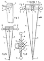
- the armature 1 is designed in the manner of a lance, in such a way that it has two flat side plates 1 ′, 1 ′′ standing at an angle to one another, which taper conically downwards towards a driving-in point 3.
- a plurality of flat side plates or curved side plates for example curved in part-circular fashion, are provided which taper downwards or run out into a tip and form the lance leaf.
- the two side plates 1 ', 1'' are of the same shape and size. They can be trapezoidal, triangular, preferably rectangular triangular, and can be arranged with respect to one another such that, in the case of a rectangular triangular or trapezoidal configuration, the right angles lie in the upper region of the anchor lance.
- the side plates 1 ', 1'' have the same plan shape results in a lance leaf which, seen in plan view (see FIG. 3), forms an isosceles triangle which is delimited by the upper edges 9, 9'.
- the side plates 1 ′, 1 ′′ accordingly collide in the apex 6 and are firmly welded to one another along this apex edge 6, for example, or, if they are made from one piece, bent toward one another in the region of this apex.
- the upper edges 9, 9 ' are covered by an end plate 10 which is welded onto these edges or in some other way Way associated with these.
- This end plate thus serves to drive the anchor in, for example by driving the anchor into the ground with a rubber hammer or with the interposition of an extension rod.
- the cover plate 10 being supported on the edges 9, 9 'of the side plates 1, 1', the compressive forces which occur during driving are introduced directly into the side plates 1 ', 1''and guided to the anchor tip 3 in a straight line.
- a holder 5 or a similar connection means is expediently attached.
- This can be an eyelet 5, as shown in the exemplary embodiment, or a hook or another suitable fastening part for a rope or chain leading, for example, to the boat.
- this holder 5 is provided approximately parallel to the end plate 10 and is attached to the underside of the end plate, for example by welding.
- On the top of the end plate 10 there is a plug-in part, which is also preferably firmly connected to this by welding. It can be a sleeve 11 which is intended for receiving the anchor shaft 2 (cf. FIG. 5) or a telescopic rod as shown in FIG. 4.
- connection between the receiving sleeve 11 and the optionally insertable anchor shaft 2 in a form-fitting manner, for example by means of a threaded connection, in order to prevent unintentional loosening.
- a screw-in piece 23 is provided at the base of the anchor rod 2, which has a suitable extension 23 'for insertion into the anchor base 2' and a pin 23 '' for screwing into the holder 11 of the end plate 10.
- a corresponding head piece 24 is provided, which can be screwed into the internal thread 2 ′′ of the anchor shaft 2 with a pin 24 ′.
- a transverse bore 25 for pushing through a transverse bolt and a thread receptacle 26 for screwing in a further connecting piece can be provided in the head piece 24 .
- a signal such as a boat flag, a lamp or the like. To be attached.
- the receiving sleeve 11 is, as already mentioned, welded onto the triangular top end plate 10 and has an internal thread which corresponds to the external thread at the upper end of the anchor shaft 2, so that a secure, permanent connection is produced by screwing in the anchor shaft 2. Instead of this screw connection, a positive locking can also occur. It is advantageous, however, that this connection and thus the position of the receiving sleeve 11 is in the vicinity of the apex 6 of the two side plates 1 ', 1' 'which are at an angle to one another, because in this way forces introduced directly via the rod 2 into the actual anchor 1 , that is, without major bending moments occurring, be introduced in the shortest possible way down into the side plates 1 ', 1' '.
- the receiving sleeve 11 has a left-hand thread.
- a corresponding left-hand thread is screwed into this at the lower end of the anchor shaft 2 if the connection between the anchor shaft 2 and the receiving sleeve 11 is to be established.
- a threaded connection is also preferably provided at the upper end of the anchor shaft 2 in order to be able to extend the anchor shaft 2 by screwing in further rods in the case of correspondingly deep water.
- This threaded connection consists of right-hand thread, as well as other connections that are required when screwing together three or four extension rods.
- a rod connection can also occur on the holder 8.
- a telescopic rod 21 in which the two telescoping tubes 13, 13 'cooperate with a spring 14 such that the telescopic rod 21 when appropriate forces occur, for example when the ship through waves is moved, can yield.
- This telescopic rod 21 can be set up so that it can be connected to the lance-shaped anchor 1 via the receiving sleeve 11 with a corresponding adaptation of the connecting pieces.
- the telescopic rod 21 has an adapter piece 15 which has a threaded attachment 15 'in a recess provided with an internal thread 16 can be screwed into the foot area of the telescopic rod 13.
- a screw-in opening 13a with a thread can also be arranged, into which, for example, a snap hook, an eyelet or the like 22 is screwed with a threaded connector.
- the telescopic rod 21 can thus be used as a cross connector or, with a corresponding inclined position, also as a shaft which is directly connected to the anchor in a form-fitting manner.
- corresponding receiving openings 17, 17 'on the side plates 1', 1 '' are provided in the upper region of the armature 1, preferably below the holder 5, through which, for example, a longer, displaceable transverse bolt 18 with spherical handles 18 'provided at both ends , 18 'engages.
- These spherical handles form end parts for the cross bolt and are screwed onto it, for example, so that they can be removed at any time when the cross bolt is removed.
- the cross bolt has a clearly protruding length over the side plates, such that it can be gripped safely with both hands, for example for pulling the anchor out of the ground.
- the bolt has sufficient play in the holes 17, 17 'such that it can be easily pushed to one of the two sides if this is necessary for handling, in which case the end parts 18' each have fixed stops as a safeguard against inadvertent falling out of the cross pin 18 form.
- a cable pulley 19 is rotatably seated on the cross pin 18.
- the legs of the eyelet 5 are advantageously parallel to one another, taking up the upper partial circumference of the pulley 19 between them, as shown in FIG is clearly drawn.
- the anchor design according to the invention has the advantage that it enables an optimally stable and secure attachment of the anchor in sandy, loamy subsoil covered with vegetation or the like, which is particularly advantageous for anchoring ships in canals, rivers, etc.
- the lance-like anchor is particularly suitable for creating an anchor point outside the river bed, i.e. on the banks or in the area of headlands, in bays or the like.
- the anchor can be easily driven into the ground near the boat, so that tensioning by means of long Ropes, as was customary up to now, or become unnecessary by means of chains in distant trees, rocky outcrops, etc.
- the anchor can be combined with one or more identical, but smaller-sized anchors (cf. FIG. 1a), with which the ship can also be anchored at several points if necessary.
- the arrangement of the eyelet 5 and the rollers 19 can be dispensed with, since it can suffice to simply anchor the anchoring rope for the additional anchoring by means of the smaller anchors via the cross bolt 18 or - as drawn in FIG. 1a - via a snap hook, to lead an eyelet or the like.
Landscapes
- Chemical & Material Sciences (AREA)
- Engineering & Computer Science (AREA)
- Combustion & Propulsion (AREA)
- Mechanical Engineering (AREA)
- Ocean & Marine Engineering (AREA)
- Piles And Underground Anchors (AREA)
- Revetment (AREA)
Applications Claiming Priority (2)
| Application Number | Priority Date | Filing Date | Title |
|---|---|---|---|
| DE19924228183 DE4228183C2 (de) | 1992-08-25 | 1992-08-25 | Von Hand einzutreibender Anker |
| DE4228183 | 1992-08-25 |
Publications (1)
| Publication Number | Publication Date |
|---|---|
| EP0591663A1 true EP0591663A1 (fr) | 1994-04-13 |
Family
ID=6466368
Family Applications (1)
| Application Number | Title | Priority Date | Filing Date |
|---|---|---|---|
| EP93113320A Withdrawn EP0591663A1 (fr) | 1992-08-25 | 1993-08-20 | Ancre, spécialement pour l'emploie dans les rivières |
Country Status (2)
| Country | Link |
|---|---|
| EP (1) | EP0591663A1 (fr) |
| DE (1) | DE4228183C2 (fr) |
Cited By (1)
| Publication number | Priority date | Publication date | Assignee | Title |
|---|---|---|---|---|
| GB2289609A (en) * | 1995-07-21 | 1995-11-29 | Maritime Mechanic Ltd | Anchoring structure for off shore beach net |
Citations (3)
| Publication number | Priority date | Publication date | Assignee | Title |
|---|---|---|---|---|
| CH334525A (de) * | 1955-02-21 | 1958-12-15 | Geschwister Huber Geraetebau | Verankerungsvorrichtung, beispielsweise für die Verankerung von Halteseilen am Boden |
| US4756128A (en) * | 1987-07-30 | 1988-07-12 | Danieli Edmund R | Beach anchor |
| US4960064A (en) * | 1989-10-17 | 1990-10-02 | Mestas Gilbert L | Land anchor for a boat |
Family Cites Families (3)
| Publication number | Priority date | Publication date | Assignee | Title |
|---|---|---|---|---|
| US3187705A (en) * | 1963-03-27 | 1965-06-08 | Gen Motors Corp | Dynamic anchor |
| DE7241166U (de) * | 1972-11-09 | 1973-02-01 | Schulte K | Zeltpflock |
| US3850128A (en) * | 1973-07-16 | 1974-11-26 | Ocean Science & Eng | Vibratory anchor |
-
1992
- 1992-08-25 DE DE19924228183 patent/DE4228183C2/de not_active Expired - Fee Related
-
1993
- 1993-08-20 EP EP93113320A patent/EP0591663A1/fr not_active Withdrawn
Patent Citations (3)
| Publication number | Priority date | Publication date | Assignee | Title |
|---|---|---|---|---|
| CH334525A (de) * | 1955-02-21 | 1958-12-15 | Geschwister Huber Geraetebau | Verankerungsvorrichtung, beispielsweise für die Verankerung von Halteseilen am Boden |
| US4756128A (en) * | 1987-07-30 | 1988-07-12 | Danieli Edmund R | Beach anchor |
| US4960064A (en) * | 1989-10-17 | 1990-10-02 | Mestas Gilbert L | Land anchor for a boat |
Cited By (2)
| Publication number | Priority date | Publication date | Assignee | Title |
|---|---|---|---|---|
| GB2289609A (en) * | 1995-07-21 | 1995-11-29 | Maritime Mechanic Ltd | Anchoring structure for off shore beach net |
| GB2289609B (en) * | 1995-07-21 | 1997-07-23 | Maritime Mechanic Ltd | Improvements for a beach net |
Also Published As
| Publication number | Publication date |
|---|---|
| DE4228183C2 (de) | 1995-12-21 |
| DE4228183A1 (de) | 1994-03-03 |
Similar Documents
| Publication | Publication Date | Title |
|---|---|---|
| DE2948230C2 (de) | Schnurgerüststütze mit Verankerungsvorrichtung | |
| DE2744774A1 (de) | Haltevorrichtung fuer einen segelmast | |
| DE2460867C3 (de) | Vorrichtung zum Verbinden von Schalungselementen | |
| DE102019122106B3 (de) | Zaunerweiterungsvorrichtung | |
| EP0591663A1 (fr) | Ancre, spécialement pour l'emploie dans les rivières | |
| DE694797C (de) | Anker fuer Zelte, Masten, Tarnungen o. dgl. | |
| DE2202131B2 (de) | Stütze zum Herstellen von Schnurgerüsten | |
| DE19604722C2 (de) | Erdschraubnagel mit Adapter | |
| DE8324791U1 (de) | Verankerungsvorrichtung fuer pfaehle oder dgl. | |
| DE2559229A1 (de) | Stuetzfuss fuer gerueste | |
| DE2447000A1 (de) | Anker | |
| DE102011120825A1 (de) | Vorrichtung zur Innenreinigung eines Silos | |
| DE102020134623B4 (de) | Befestigungsanordnung zur Bodenbefestigung | |
| DE4228182C2 (de) | Schiffs-, insbesondere Bootsanker mit annähernd flachem, plattenförmigem Ankerblatt | |
| DE3904499A1 (de) | Stuetzbein fuer einen geruestpfahl | |
| DE1459804C (de) | Schneezaun | |
| DE1258574B (de) | Vorrichtung zur Montage von zwei- oder mehrteiligen Masten | |
| DE1946274U (de) | Vorrichtung zum aufspannen von randschalungen auf stahlformboeden. | |
| DE7521860U (de) | Zaunpfosten | |
| DE10225955A1 (de) | Gitter, Zaun sowie Fenstergitter und Türgitter | |
| DE2248763A1 (de) | Zaunpfahl und damit ausgeruesteter zaun | |
| DE29717674U1 (de) | Halterung für Spanndrähte | |
| DE4121050A1 (de) | Vorrichtung zum sichern, insbesondere verzurren, eines gegenstandes, insbesondere eines containers | |
| DE7300050U (de) | Arbeitsgeruest fuer bauwerke | |
| DE9010140U1 (de) | Vorrichtung zum Verbinden zweier sich kreuzender Träger |
Legal Events
| Date | Code | Title | Description |
|---|---|---|---|
| PUAI | Public reference made under article 153(3) epc to a published international application that has entered the european phase |
Free format text: ORIGINAL CODE: 0009012 |
|
| AK | Designated contracting states |
Kind code of ref document: A1 Designated state(s): BE DE DK ES FR GB GR IT NL PT SE |
|
| 18D | Application deemed to be withdrawn |
Effective date: 19941014 |