EP0591663A1 - Anchor, especially for use in rivers - Google Patents
Anchor, especially for use in rivers Download PDFInfo
- Publication number
- EP0591663A1 EP0591663A1 EP93113320A EP93113320A EP0591663A1 EP 0591663 A1 EP0591663 A1 EP 0591663A1 EP 93113320 A EP93113320 A EP 93113320A EP 93113320 A EP93113320 A EP 93113320A EP 0591663 A1 EP0591663 A1 EP 0591663A1
- Authority
- EP
- European Patent Office
- Prior art keywords
- anchor
- side plates
- anchor according
- eyelet
- end plate
- Prior art date
- Legal status (The legal status is an assumption and is not a legal conclusion. Google has not performed a legal analysis and makes no representation as to the accuracy of the status listed.)
- Withdrawn
Links
Images

Classifications
-
- B—PERFORMING OPERATIONS; TRANSPORTING
- B63—SHIPS OR OTHER WATERBORNE VESSELS; RELATED EQUIPMENT
- B63B—SHIPS OR OTHER WATERBORNE VESSELS; EQUIPMENT FOR SHIPPING
- B63B21/00—Tying-up; Shifting, towing, or pushing equipment; Anchoring
- B63B21/24—Anchors
- B63B21/26—Anchors securing to bed
Definitions
- the invention relates to an anchor for securing ships, boats or the like.
- Water vehicles in a fastening base inside or outside a water bed which is particularly suitable for anchoring in river beds.
- the usual anchors for anchoring ships or other watercraft in river beds, canals, bays or the like are only extremely suitable due to their complex construction and the mostly small space requirement for anchoring in river beds, so that anchoring in such cases is usually done by means of tensioned ropes to the bank or to other attachment points in the bank area.
- the disadvantage here is that such tensioning ropes for anchoring watercraft hinder the route for other ships or the like.
- anchoring by means of ropes, chains or the like requires cumbersome and complex auxiliary work. The tension cables also take up unnecessary space and thus hinder other watercraft.
- the anchor has at least two side plates enclosing an angle ⁇ between 60 and 130 °, which taper towards the bottom, with an impact plate for driving the anchor into the fastening base and a holder for its connection in the upper region of the side plates the watercraft or the like are provided.
- the armature 1 is designed in the manner of a lance, in such a way that it has two flat side plates 1 ′, 1 ′′ standing at an angle to one another, which taper conically downwards towards a driving-in point 3.
- a plurality of flat side plates or curved side plates for example curved in part-circular fashion, are provided which taper downwards or run out into a tip and form the lance leaf.
- the two side plates 1 ', 1'' are of the same shape and size. They can be trapezoidal, triangular, preferably rectangular triangular, and can be arranged with respect to one another such that, in the case of a rectangular triangular or trapezoidal configuration, the right angles lie in the upper region of the anchor lance.
- the side plates 1 ', 1'' have the same plan shape results in a lance leaf which, seen in plan view (see FIG. 3), forms an isosceles triangle which is delimited by the upper edges 9, 9'.
- the side plates 1 ′, 1 ′′ accordingly collide in the apex 6 and are firmly welded to one another along this apex edge 6, for example, or, if they are made from one piece, bent toward one another in the region of this apex.
- the upper edges 9, 9 ' are covered by an end plate 10 which is welded onto these edges or in some other way Way associated with these.
- This end plate thus serves to drive the anchor in, for example by driving the anchor into the ground with a rubber hammer or with the interposition of an extension rod.
- the cover plate 10 being supported on the edges 9, 9 'of the side plates 1, 1', the compressive forces which occur during driving are introduced directly into the side plates 1 ', 1''and guided to the anchor tip 3 in a straight line.
- a holder 5 or a similar connection means is expediently attached.
- This can be an eyelet 5, as shown in the exemplary embodiment, or a hook or another suitable fastening part for a rope or chain leading, for example, to the boat.
- this holder 5 is provided approximately parallel to the end plate 10 and is attached to the underside of the end plate, for example by welding.
- On the top of the end plate 10 there is a plug-in part, which is also preferably firmly connected to this by welding. It can be a sleeve 11 which is intended for receiving the anchor shaft 2 (cf. FIG. 5) or a telescopic rod as shown in FIG. 4.
- connection between the receiving sleeve 11 and the optionally insertable anchor shaft 2 in a form-fitting manner, for example by means of a threaded connection, in order to prevent unintentional loosening.
- a screw-in piece 23 is provided at the base of the anchor rod 2, which has a suitable extension 23 'for insertion into the anchor base 2' and a pin 23 '' for screwing into the holder 11 of the end plate 10.
- a corresponding head piece 24 is provided, which can be screwed into the internal thread 2 ′′ of the anchor shaft 2 with a pin 24 ′.
- a transverse bore 25 for pushing through a transverse bolt and a thread receptacle 26 for screwing in a further connecting piece can be provided in the head piece 24 .
- a signal such as a boat flag, a lamp or the like. To be attached.
- the receiving sleeve 11 is, as already mentioned, welded onto the triangular top end plate 10 and has an internal thread which corresponds to the external thread at the upper end of the anchor shaft 2, so that a secure, permanent connection is produced by screwing in the anchor shaft 2. Instead of this screw connection, a positive locking can also occur. It is advantageous, however, that this connection and thus the position of the receiving sleeve 11 is in the vicinity of the apex 6 of the two side plates 1 ', 1' 'which are at an angle to one another, because in this way forces introduced directly via the rod 2 into the actual anchor 1 , that is, without major bending moments occurring, be introduced in the shortest possible way down into the side plates 1 ', 1' '.
- the receiving sleeve 11 has a left-hand thread.
- a corresponding left-hand thread is screwed into this at the lower end of the anchor shaft 2 if the connection between the anchor shaft 2 and the receiving sleeve 11 is to be established.
- a threaded connection is also preferably provided at the upper end of the anchor shaft 2 in order to be able to extend the anchor shaft 2 by screwing in further rods in the case of correspondingly deep water.
- This threaded connection consists of right-hand thread, as well as other connections that are required when screwing together three or four extension rods.
- a rod connection can also occur on the holder 8.
- a telescopic rod 21 in which the two telescoping tubes 13, 13 'cooperate with a spring 14 such that the telescopic rod 21 when appropriate forces occur, for example when the ship through waves is moved, can yield.
- This telescopic rod 21 can be set up so that it can be connected to the lance-shaped anchor 1 via the receiving sleeve 11 with a corresponding adaptation of the connecting pieces.
- the telescopic rod 21 has an adapter piece 15 which has a threaded attachment 15 'in a recess provided with an internal thread 16 can be screwed into the foot area of the telescopic rod 13.
- a screw-in opening 13a with a thread can also be arranged, into which, for example, a snap hook, an eyelet or the like 22 is screwed with a threaded connector.
- the telescopic rod 21 can thus be used as a cross connector or, with a corresponding inclined position, also as a shaft which is directly connected to the anchor in a form-fitting manner.
- corresponding receiving openings 17, 17 'on the side plates 1', 1 '' are provided in the upper region of the armature 1, preferably below the holder 5, through which, for example, a longer, displaceable transverse bolt 18 with spherical handles 18 'provided at both ends , 18 'engages.
- These spherical handles form end parts for the cross bolt and are screwed onto it, for example, so that they can be removed at any time when the cross bolt is removed.
- the cross bolt has a clearly protruding length over the side plates, such that it can be gripped safely with both hands, for example for pulling the anchor out of the ground.
- the bolt has sufficient play in the holes 17, 17 'such that it can be easily pushed to one of the two sides if this is necessary for handling, in which case the end parts 18' each have fixed stops as a safeguard against inadvertent falling out of the cross pin 18 form.
- a cable pulley 19 is rotatably seated on the cross pin 18.
- the legs of the eyelet 5 are advantageously parallel to one another, taking up the upper partial circumference of the pulley 19 between them, as shown in FIG is clearly drawn.
- the anchor design according to the invention has the advantage that it enables an optimally stable and secure attachment of the anchor in sandy, loamy subsoil covered with vegetation or the like, which is particularly advantageous for anchoring ships in canals, rivers, etc.
- the lance-like anchor is particularly suitable for creating an anchor point outside the river bed, i.e. on the banks or in the area of headlands, in bays or the like.
- the anchor can be easily driven into the ground near the boat, so that tensioning by means of long Ropes, as was customary up to now, or become unnecessary by means of chains in distant trees, rocky outcrops, etc.
- the anchor can be combined with one or more identical, but smaller-sized anchors (cf. FIG. 1a), with which the ship can also be anchored at several points if necessary.
- the arrangement of the eyelet 5 and the rollers 19 can be dispensed with, since it can suffice to simply anchor the anchoring rope for the additional anchoring by means of the smaller anchors via the cross bolt 18 or - as drawn in FIG. 1a - via a snap hook, to lead an eyelet or the like.
Landscapes
- Chemical & Material Sciences (AREA)
- Engineering & Computer Science (AREA)
- Combustion & Propulsion (AREA)
- Mechanical Engineering (AREA)
- Ocean & Marine Engineering (AREA)
- Piles And Underground Anchors (AREA)
- Revetment (AREA)
Abstract
Description
Die Erfindung bezieht sich auf einen Anker zur Sicherung von Schiffen, Booten oder dgl. Wasserfahrzeugen in einem Befestigungsgrund innerhalb oder außerhalb eines Wasserbettes, der insbesondere zur Verankerung in Flußbetten geeignet ist. Bekanntlich sind die üblichen Anker zur Verankerung von Schiffen oder anderen Wasserfahrzeugen in Flußbetten, Kanälen, Buchten oder dgl. wegen ihres aufwendigen konstruktiven Aufbaus und des bei Ankerungen in Flußbetten meist geringen Platzbedarfes nur äußerst beschränkt geeignet, so daß Verankerungen in solchen Fällen meist mittels gespannter Seile zum Ufer oder zu anderen Befestigungspunkten im Uferbereich gewählt werden. Nachteilig ist dabei, daß solche Spannseile zur Verankerung von Wasserfahrzeugen den Fahrweg für andere Schiffe oder dgl. behindern, wobei zudem die Verankerung mittels Seilen, Ketten oder dgl. umständliche und aufwendige Hilfsarbeiten erfordern. Die Spannseile nehmen zudem unnötigen Platz in Anspruch und behindern dadurch andere Wasserfahrzeuge.The invention relates to an anchor for securing ships, boats or the like. Water vehicles in a fastening base inside or outside a water bed, which is particularly suitable for anchoring in river beds. As is known, the usual anchors for anchoring ships or other watercraft in river beds, canals, bays or the like are only extremely suitable due to their complex construction and the mostly small space requirement for anchoring in river beds, so that anchoring in such cases is usually done by means of tensioned ropes to the bank or to other attachment points in the bank area. The disadvantage here is that such tensioning ropes for anchoring watercraft hinder the route for other ships or the like. In addition, anchoring by means of ropes, chains or the like requires cumbersome and complex auxiliary work. The tension cables also take up unnecessary space and thus hinder other watercraft.
Es ist daher Aufgabe der Erfindung, einen Anker der eingangs erwähnten Art zu schaffen, der eine stabile und sichere Verankerung von Schiffen, Booten oder dgl. in Niedriggewässern, insbesondere in Flußbetten, räumlich begrenzten Buchten ermöglicht und die bisherige umständliche Anwendung von Verspannungsseilen entbehrlich macht.It is therefore an object of the invention to provide an anchor of the type mentioned at the outset, which enables stable and secure anchoring of ships, boats or the like in low water, in particular in river beds, spatially limited bays and makes the previously cumbersome use of tension cables unnecessary.
Gemäß der Erfindung weist der Anker mindestens zwei einen Winkel α zwischen 60 und 130° miteinander einschließende Seitenplatten auf, die sich nach unten hin verjüngen, wobei im oberen Bereich der Seitenplatten eine Aufschlagplatte zum Eintreiben des Ankers in den Befestigungsgrund sowie eine Halterung zu seiner Verbindung mit dem Wasserfahrzeug oder dgl. vorgesehen sind.According to the invention, the anchor has at least two side plates enclosing an angle α between 60 and 130 °, which taper towards the bottom, with an impact plate for driving the anchor into the fastening base and a holder for its connection in the upper region of the side plates the watercraft or the like are provided.
Bei einer bevorzugten Ausführungsform besteht der Anker aus zwei Seitenplatten, die nach Form und Größe gleich ausgebildet sind. Die Platten sind vorteilhaft trapez- bzw. rechtwinklig dreieckförmig oder teilkreisförmig gebogen gestaltet und so zueinander angeordnet und miteinander verbunden, daß sie im oberen Bereich des Ankers einen rechten Winkel einschließen und sich nach unten zu zu einer Eintreibspitze verjüngen. In diesem oberen Bereich wird zur Erhöhung der Stabilität des Ankers und zu seiner leichteren Eintreibbarkeit in den Wassergrund die Abschlußplatte vorgesehen, die die beiden Seitenplatten vorzugsweise von oben her abdeckt und mit diesen derart fest verbunden ist, daß ein stabiler, unverwindbarer und biegesteifer Anker nach Art einer Lanze geschaffen ist. Weitere Merkmale des erfindungsgemäßen Ankers ergeben sich aus der nachstehenden Beschreibung eines Ausführungsbeispieles, das in der Zeichnung dargestellt ist. Es zeigen:
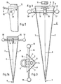
- Fig. 1
- den Anker in Ansicht auf seine geöffnete Frontseite,
- Fig. 1a
- zeigt den Anker in kleinerer Ausführung, der als Hilfsanker eingesetzt werden kann,
- Fig. 2
- eine Teilansicht des Ankers nach Fig. 1 von der Seite in Richtung des Pfeiles II,
- Fig. 3
- eine Draufsicht auf den oberen Teil des Ankers entsprechend Fig. 2,
- Fig. 4
- zeigt eine beispielsweise Ausführung einer Teleskopstange, die sowohl als Ankerschaft als auch als Querverbindung zum Schiff bzw. zu einer Uferbefestigung dienen kann,
- Fig. 5
- zeigt ein Beispiel eines Ankerschaftes, der mit dem erfindungsgemäß ausgebildeten Anker formschlüssig verbunden werden kann.
- Fig. 1
- the anchor in view of its open front,
- Fig. 1a
- shows the anchor in a smaller version, which can be used as an auxiliary anchor,
- Fig. 2
- 1 from the side in the direction of arrow II,
- Fig. 3
- 2 shows a top view of the upper part of the armature corresponding to FIG.
- Fig. 4
- shows an example of a design of a telescopic rod that can serve both as an anchor shaft and as a cross-connection to the ship or to a bank attachment,
- Fig. 5
- shows an example of an anchor shaft that can be positively connected to the anchor designed according to the invention.
Wie insbesondere aus Fig. 1 ersichtlich, ist der Anker 1 nach Art einer Lanze ausgebildet, derart, daß er zwei im Winkel zueinander stehende flache Seitenplatten 1', 1'' hat, die sich nach unten zu einer Eintreibspitze 3 hin konisch verjüngen. Es sind Ausführungsformen denkbar, bei denen anstelle von zwei winklig zueinander gestellten Seitenplatten mehrere flache oder auch im Querschnitt gekrümmte, beispielsweise teilkreisförmig gebogene Seitenplatten, vorgesehen sind, die sich nach unten verjüngen bzw. in eine Spitze auslaufen und das Lanzenblatt bilden. Bei der herstellungsmäßig einfachen Ausbildung mit zwei flachen Seitenplatten 1', 1'' beträgt der Winkel, den diese beiden Platten einschließen vorteilhaft 90°, um eine gute Standsicherheit bei optimalem Lanzenvolumen sowie ein kraftsparendes Eintreiben der Lanze zu erhalten. Diesem Zweck dient es auch, wenn nach einem weiteren Merkmal der Erfindung die beiden Seitenplatten 1', 1'' in ihrer Form und ihrer Größe gleich ausgebildet sind. Dabei können sie trapezförmig, dreieckförmig, vorzugsweise rechtwinklig dreieckförmig ausgebildet und so zueinander angeordnet sein, daß bei rechteckig dreieckförmiger oder trapezförmiger Ausbildung die rechten Winkel im oberen Bereich der Ankerlanze liegen. Dadurch daß die Seitenplatten 1', 1'' gleiche Grundrißform haben, ergibt sich ein Lanzenblatt, das in Draufsicht (vgl. Fig. 3) gesehen ein gleichschenkliges Dreieck bildet, das durch die oberen Ränder 9, 9' begrenzt ist. Die Seitenplatten 1', 1'' stoßen demgemäß im Scheitel 6 zusammen und sind längs dieser Scheitelkante 6 fest miteinander beispielsweise verschweißt oder, wenn sie aus einem Stück hergestellt sind, im Bereich dieses Scheitels zueinander abgebogen. Zur Bildung einer Aufschlagfläche für die Druck-, Stoß- oder Schlagkräfte beim Eintreiben des Ankers in den Ankergrund sowie zur Erhöhung der Stabilität dieses lanzenartigen Ankers sind die oberen Ränder 9, 9' durch eine Abschlußplatte 10 abgedeckt, die auf diese Ränder aufgeschweißt oder in sonstiger Weise mit diesen verbunden sein kann. Diese Abschlußplatte dient somit zum Einschlagen des Ankers, indem beispielsweise mit einem Gummihammer oder unter Zwischenschaltung einer Verlängerungsstange der Anker in den Untergrund eingetrieben wird. Durch die Auflagerung der Abdeckplatte 10 auf den Rändern 9, 9' der Seitenplatten 1, 1' werden die beim Eintreiben auftretenden Druckkräfte unmittelbar in die Seitenplatten 1', 1'' eingeleitet und zur Ankerspitze 3 hin auf geradlinigem Wege geführt.As can be seen in particular from FIG. 1, the
Im Bereich der oberen Abschlußplatte 10 ist zweckmäßig eine Halterung 5 oder ein ähnliches Anschlußmittel angebracht. Dies kann eine Öse 5, wie im Ausführungsbeispiel gezeigt, oder ein Haken oder ein anderes geeignetes Befestigungsteil für ein beispielsweise zum Boot führendes Seil oder eine Kette sein. Vorteilhaft ist es, wenn diese Halterung 5 etwa parallel zur Abschlußplatte 10 vorgesehen wird und an der Unterseite der Abschlußplatte beispielsweise durch Schweißen befestigt ist. Auf der Oberseite der Abschlußplatte 10 befindet sich ein Einsteckteil, das mit dieser ebenfalls vorzugsweise durch Schweißen fest verbunden ist. Es kann eine Muffe 11 sein, die zur Aufnahme des Ankerschaftes 2 (vgl. Fig. 5) bzw. einer Teleskopstange entsprechend der Darstellung nach Fig. 4 bestimmt ist. Dabei ist es zweckmäßig, die Verbindung zwischen Aufnahmemuffe 11 und dem wahlweisen einsteckbaren Ankerschaft 2 formschlüssig, beispielsweise durch eine Gewindeverbindung, auszubilden, um ein unbeabsichtigtes Lösen zu verhindern. Bei der Ankerstange nach Fig. 5 ist hierzu am Fuß der Ankerstange 2 ein Einschraubstück 23 vorgesehen, das einen passenden Ansatz 23' zum Einstecken in den Ankerfuß 2' hat und einen Zapfen 23'' zum Einschrauben in die Halterung 11 der Abschlußplatte 10. Am anderen Ende des Ankerschaftes 2 entsprechend Fig. 5 ist ein entsprechendes Kopfstück 24 vorgesehen, das mit einem Zapfen 24' in das Innengewinde 2'' des Ankerschaftes 2 einschraubbar ist. In dem Kopfstück 24 kann eine Querbohrung 25 zum Durchstecken eines Querbolzens und eine Gewindeaufnahme 26 zum Einschrauben eines weiteren Verbindungsstückes vorgesehen sein. Auf diese Weise kann eine beliebig lange vertikal vom eigentlichen Anker nach oben über den Wasserspiegel reichende Stangenverbindung hergestellt werden, wobei am obersten aus dem Wasser vorstehenden Ende mittels eines einschraubbaren Bolzens oder dgl. ein Signal, z.B. eine Bootsfahne, eine Lampe oder dgl., befestigt werden.In the area of the
Die Aufnahmemuffe 11 ist, wie schon erwähnt, auf die dreieckförmige obere Abschlußplatte 10 aufgeschweißt und hat ein Innengewinde, das mit dem Außengewinde am oberen Ende des Ankerschaftes 2 korrespondiert, so daß durch Einschrauben des Ankerschaftes 2 eine sichere, unlösbare Verbindung hergestellt wird. Anstelle dieser Schraubverbindung kann ebenfalls eine formschlüssige andere Verriegelung treten. Von Vorteil ist aber, daß diese Verbindung und damit die Lage der Aufnahmemuffe 11 in der Nähe des Scheitels 6 der beiden im Winkel zueinander liegenden Seitenplatten 1', 1'' liegt, weil dadurch über die Stange 2 in den eigentlichen Anker 1 eingeleitete Kräfte unmittelbar, also ohne daß größere Biegemomente auftreten, auf kürzestem Wege nach unten zu in die Seitenplatten 1', 1'' eingeleitet werden.The
Die Aufnahmemuffe 11 weist ein Linksgewinde auf. In dieses wird ein entsprechendes Linksgewinde am unteren Ende des Ankerschaftes 2 eingeschraubt, wenn die Verbindung zwischen Ankerschaft 2 und Aufnahmemuffe 11 hergestellt werden soll. Am oberen Ende des Ankerschaftes 2 ist ebenfalls bevorzugt eine Gewindeverbindung vorgesehen, um den Ankerschaft 2 durch Einschrauben weiterer Stangen bei entsprechend tiefem Wasser verlängern zu können. Diese Gewindeverbindung besteht aber aus Rechtsgewinde, ebenso weitere Verbindungen, die bei Zusammenschrauben von drei oder vier Verlängerungsstangen erforderlich werden. Dadurch, daß die unterste Verbindung zwischen dem unteren Ende des Ankerschaftes 2 und der Aufnahmemuffe 11 des Ankers 1 ein Linksgewinde hat und die übrigen Gewindeverbindungen zwischen den Verlängerungsstangen Rechtsgewinde aufweisen, ist sichergestellt, daß beim Herausdrehen des Ankerschaftes 2 samt Verlängerungsstangen der eingetriebene Anker 1 nicht aus seiner eingetriebenen Lage gelöst werden kann. Das Einschrauben des Ankerschaftes 2 ist jedenfalls dann notwendig, wenn der Wasserstand so hoch ist, daß er den Anker übersteigt, so daß das Eintreiben des Ankers nur bei eingeschraubtem Ankerschaft 2 oder bei noch höherem Wasserstand durch entsprechende Verlängerung des Ankerschaftes 2 mittels zusätzlicher Verlängerungsstangen möglich ist. Das Eintreiben des Ankers erfolgt dann durch Aufschlagen auf das oberste aus dem Wasser herausragende Ende der letzten Verlängerungsstange. Die eigentliche Sicherung zwischen Anker und Schiff erfolgt mittels eines Seiles einer Kette oder dgl., die in die Halterung 5, vorzugsweise eine Öse, eingefädelt wird.The receiving
Anstelle einer Seil- oder Kettenverbindung zu dem zu verankernden Boot, Schiff oder dgl. kann an die Halterung 8 auch eine Stangenverbindung treten. Als Beispiel für eine solche Verbindung ist in Fig. 4 eine Teleskopstange 21 gezeigt, bei der die beiden ineinander teleskopierbaren Rohre 13, 13' mit einer Feder 14 derart zusammenwirken, daß die Teleskopstange 21 bei Auftreten entsprechender Kräfte, beispielsweise, wenn das Schiff durch Wellen bewegt wird, nachgeben kann. Diese Teleskopstange 21 kann so eingerichtet sein, daß sie mit dem lanzenförmigen Anker 1 über die Aufnahmemuffe 11 bei entsprechender Anpassung der Verbindungsstücke verbunden werden kann. Um solche möglichst vielseitige Verbindungsmöglichkeiten zu schaffen, weist die Teleskopstange 21 ein Adapterstück 15 auf, das mit einem Gewindeansatz 15' in eine mit Innengewinde versehene Ausnehmung 16 im Fußbereich der Teleskopstange 13 einschraubbar ist. Am anderen Ende der Teleskopstange 21 kann, wie im Ausführungsbeispiel nach Fig. 4 gezeigt, ebenfalls eine Einschrauböffnung 13a mit Gewinde angeordnet sein, in die beispielsweise ein Karabinerhaken, eine Öse oder dgl. 22 mit Gewindestutzen eingeschraubt wird. Die teleskopierbare Stange 21 kann also als Querverbinder oder bei entsprechender Schräglage auch als Schaft, der unmittelbar mit dem Anker formschlüssig verbunden wird, verwendet werden.Instead of a cable or chain connection to the boat, ship or the like to be anchored, a rod connection can also occur on the holder 8. As an example of such a connection is shown in Fig. 4, a
Schließlich sind im oberen Bereich des Ankers 1, vorzugsweise unterhalb der Halterung 5, korrespondierende Aufnahmeöffnungen 17, 17' an den Seitenplatten 1', 1'' vorgesehen, durch die beispielsweise ein längerer, verschiebbarer Querbolzen 18 mit an beiden Enden vorgesehenen kugelförmigen Handhaben 18', 18' greift. Diese kugelförmigen Handhaben bilden Abschlußteile für den Querbolzen und sind auf diesen beispielsweise aufgeschraubt, so daß sie beim Herausnehmen des Querbolzens jederzeit abgenommen werden können. Dabei hat der Querbolzen eine über die Seitenplatten deutlich vorstehende Länge, derart, daß er mit beiden Händen, z.B. zum Herausziehen des Ankers aus dem Untergrund, sicher erfaßt werden kann. Zudem hat der Bolzen in den Löchern 17, 17' ausreichend Spiel, derart, daß er leicht nach einer der beiden Seiten hin geschoben werden kann, wenn das zum Hantieren erforderlich ist, wobei dann die Abschlußteile 18' jeweils feste Anschläge als Sicherung gegen unbeabsichtigtes Herausfallen des Querbolzens 18 bilden. Auf dem Querbolzen 18 sitz drehbar eine Seilrolle 19. Um diese und das Seil gegen unerwünschte seitliche Verschiebung zu sichern, sind vorteilhaft die Schenkel der Öse 5 parallel zueinander, wobei sie den oberen Teilumfang der Rolle 19 zwischen sich aufnehmen, wie dies in Fig. 1 deutlich gezeichnet ist.Finally, corresponding receiving
Die erfindungsgemäße Ankerausführung hat den Vorteil, daß sie eine optimal stabile und sichere Befestigung des Ankers in sandigem, lehmigem, mit Pflanzenbewuchs oder dgl. besetztem Untergrund ermöglicht, was insbesondere zur Verankerung von Schiffen in Kanälen, Flüssen usw. von großem Vorteil ist. Darüberhinaus eignet sich der lanzenartige Anker insbesondere auch zur Erstellung einer Ankerstelle außerhalb des Flußbettes, also an Ufern oder im Bereich von Landzungen, in Buchten oder dgl.. Der Anker kann unmittelbar in Bootsnähe leicht in den Boden eingetrieben werden, so daß eine Verspannung mittels langer Seile, wie bisher üblich, oder mittels Ketten in entfernt liegenden Bäumen, Felsvorsprüngen usw. entbehrlich wird. Infolge der Anordnung von Verbindungsmitteln, insbesondere des Ankerschaftes 2 und der Teleskopstange 21, läßt sich eine sichere Verankerung und Verbindung zum Schiff oder auch zum Land herstellen, wenn der Anker außerhalb des Gewässers am Uferbereich oder dgl. in den Boden eingetrieben wird. Auf diese Weise werden platzraubende und umständlich herstellbare Seilverspannungen überflüssig. Dem Bootsfahrer wird ferner eine zeitaufwendige Suche nach außerhalb des Flußbettes befindlichen geeigneten Ankermöglichkeiten, insbesondere nach ortsfesten Befestigungsstellen wie Bäume, Felsvorsprünge usw., erspart, weil es der erfindungsgemäße Anker erlaubt, diesen auch auf festem Grund außerhalb des Flußbettes einzutreiben und von dort aus mit einer geeigneten Querstange, insbesondere der beschriebenen Teleskopstange 21 oder dgl. mit dem Boot zu verbinden. Bei unmittelbarer Verankerung im Wassergrund ist es ein wesentlicher Vorteil, daß dem Bootsfahrer bei der Suche nach einer geeigneten Verankerungsmöglichkeit für sein Boot und bei der Herstellung der üblichen Seil- bzw. Kettenverankerung das Aussteigen aus dem Boot in unsicheren Gewässern und unbekannten Umgebungen erspart bleibt.The anchor design according to the invention has the advantage that it enables an optimally stable and secure attachment of the anchor in sandy, loamy subsoil covered with vegetation or the like, which is particularly advantageous for anchoring ships in canals, rivers, etc. In addition, the lance-like anchor is particularly suitable for creating an anchor point outside the river bed, i.e. on the banks or in the area of headlands, in bays or the like. The anchor can be easily driven into the ground near the boat, so that tensioning by means of long Ropes, as was customary up to now, or become unnecessary by means of chains in distant trees, rocky outcrops, etc. As a result of the arrangement of connecting means, in particular the
Zudem kann der Anker mit einem oder mehreren gleichen, jedoch kleiner dimensionierten Ankern (vgl. Fig. 1a) kombiniert werden, mit denen das Schiff im Bedarfsfall zusätzlich an mehreren Stellen verankert werden kann. Bei diesen kleineren Ankern kann die Anordnung der Öse 5 sowie der Rollen 19 entbehrlich sein, da es genügen kann, das Verankerungsseil für die zusätzliche Verankerung mittels der kleineren Anker lediglich über den Querbolzen 18 oder - wie in Fig. 1a gezeichnet - über einen Karabinerhaken, eine Öse oder dgl. zu führen.In addition, the anchor can be combined with one or more identical, but smaller-sized anchors (cf. FIG. 1a), with which the ship can also be anchored at several points if necessary. In the case of these smaller anchors, the arrangement of the
Claims (12)
dadurch gekennzeichnet, daß der Anker mindestens zwei einen Winkel (α) zwischen 60 und 130° miteinander einschließende Seitenplatten (1', 1'') aufweist, die sich nach unten verjüngen, daß im oberen Bereich der Seitenplatten (1', 1'') eine Aufschlagplatte (10) zum Eintreiben des Ankers in den Befestigungsgrund sowie eine Halterung (5) zur Verbindung mit dem Wasserfahrzeug vorgesehen sind.Anchor to be driven in by hand to secure ships, boats or similar watercraft in low water,
characterized in that the armature has at least two side plates (1 ', 1'') which enclose an angle (α) of between 60 and 130 ° and which taper downwards in that in the upper region of the side plates (1', 1 '' ) an impact plate (10) for driving the anchor into the fastening base and a holder (5) for connection to the watercraft are provided.
dadurch gekennzeichnet, daß er aus zwei im Winkel von 90° zueinander stehenden flachen Seitenplatten (1', 1'') besteht, die sich nach unten zu einer Eintreibspitze (3) hin verjüngen, wobei jede Seitenplatte die geometrische Form eines rechtschenkligen Dreiecks hat.Anchor according to claim 1,
characterized in that it consists of two flat side plates (1 ', 1'') which are at an angle of 90 ° to one another and taper downwards towards a driving-in tip (3), each side plate having the geometric shape of a right-angled triangle.
dadurch gekennzeichnet, daß die Seitenplatten (1', 1'') trapezförmig ausgebildet sind.Anchor according to claim 1,
characterized in that the side plates (1 ', 1'') are trapezoidal.
dadurch gekennzeichnet, daß die Aufschlagplatte (10) als senkrecht zu den Seitenplatten (1', 1'') liegende obere Abschlußplatte ausgebildet ist, welche die Seitenplatten überdeckt und diese starr miteinander verbindet.Anchor according to one of claims 1 to 3,
characterized in that the impact plate (10) is designed as an upper end plate lying perpendicular to the side plates (1 ', 1''), which covers the side plates and rigidly connects them to one another.
dadurch gekennzeichnet, daß die Abschlußplatte (10) auf den oberen Rändern (9, 9') der Seitenplatten (1', 1'') aufsitzt.Anchor according to one of claims 1 to 4,
characterized in that the end plate (10) sits on the upper edges (9, 9 ') of the side plates (1', 1 '').
dadurch gekennzeichnet, daß die Halterung (5) parallel zur Abschlußplatte (10) angeordnet und als Öse, Haken oder dgl., ausgebildet ist.Anchor according to one of claims 1 to 5,
characterized in that the holder (5) is arranged parallel to the end plate (10) and is designed as an eyelet, hook or the like.
dadurch gekennzeichnet, daß die Abschlußplatte (10) einen Einsteckteil (11), beispielsweise eine mit Gewinde versehene Aufnahmemuffe, zur wahlweisen formschlüssigen Verbindung mit einem Ankerschaft (2), einer Verlängerungsstange (21) oder dgl. trägt, wobei am freien Ende des Ankerschaftes (2) oder dgl. ein Anschluß (12), beispielsweise eine Schraubmuffe, ein Haken, Öse oder dgl., vorgesehen sind.Anchor according to one of claims 1 to 6,
characterized in that the end plate (10) carries an insertion part (11), for example a threaded receiving sleeve, for optional positive connection with an anchor shaft (2), an extension rod (21) or the like, with at the free end of the anchor shaft ( 2) or the like. A connection (12), for example a screw sleeve, a hook, eyelet or the like, are provided.
dadurch gekennzeichnet, daß im oberen Bereich des Ankers (1), vorzugsweise unterhalb der Öse (5), korrespondierende Aufnahmeöffnungen (17, 17') in den Seitenplatten (1', 1'') vorgesehen sind, die von einer Handhabe, vorzugsweise in Form eines herausnehmbaren Querbolzens (18), mit endseitigen Handhaben (18') durchgriffen sind.Anchor according to one of claims 1 to 7,
characterized in that in the upper area of the armature (1), preferably below the eyelet (5), corresponding receiving openings (17, 17 ') are provided in the side plates (1', 1 ''), which can be handled, preferably in Form of a removable cross bolt (18), with end handles (18 ') are penetrated.
dadurch gekennzeichnet, daß auf dem Querbolzen (18) unterhalb der Öse (5) eine Rolle (19) angeordnet ist, vorzugsweise derart, daß ein über die Rolle (19) geführtes Seil durch die Öse (5) hindurchführbar ist.Anchor according to claim 8,
characterized in that a roller (19) is arranged on the cross bolt (18) below the eyelet (5), preferably in such a way that a rope guided over the roller (19) can be passed through the eyelet (5).
dadurch gekennzeichnet, daß die Aufnahmemuffe (11) in Draufsicht gesehen exzentrisch in der Nähe der Mitte der Seitenplatten (1', 1'') angeordnet ist.Anchor according to claim 7,
characterized in that the receiving sleeve (11) is arranged eccentrically in the vicinity of the center of the side plates (1 ', 1'') seen in plan view.
dadurch gekennzeichnet, daß der Anker mit einer Teleskopstange (21) verbindbar ist, die aus zwei ineinanderschiebbaren Teleskoprohren (13, 13') und einer im Innern dieser Rohre befindlichen Schraubenfeder (14) besteht.Anchor according to one of claims 1 to 10,
characterized in that the anchor can be connected to a telescopic rod (21) which consists of two telescopic tubes (13, 13 ') which can be pushed into one another and a helical spring (14) located inside these tubes.
dadurch gekennzeichnet, daß am fußseitigen Ende der Teleskopstange (25) ein Adapterteil (15) vorgesehen ist, das in eine korrespondierende Aufnahme (16) im Fuß des Teleskoprohres (13) beispielsweise mittels Gewinde formschlüssig einpaßt und daß ferner am kopfseitigen Ende der Teleskopstange (21) ein formschlüssig beispielsweise durch Gewinde einschraubbares Verbindungselement wie eine Öse, Karabinerhaken oder dgl. (22) einschraubbar ist.Anchor according to claim 11,
characterized in that an adapter part (15) is provided at the foot end of the telescopic rod (25), which fits positively into a corresponding receptacle (16) in the foot of the telescopic tube (13), for example by means of a thread, and also at the head end of the telescopic rod (21 ) a form-fitting screw-in connecting element such as an eyelet, snap hook or the like (22) can be screwed in.
Applications Claiming Priority (2)
| Application Number | Priority Date | Filing Date | Title |
|---|---|---|---|
| DE19924228183 DE4228183C2 (en) | 1992-08-25 | 1992-08-25 | Anchor to be driven in by hand |
| DE4228183 | 1992-08-25 |
Publications (1)
| Publication Number | Publication Date |
|---|---|
| EP0591663A1 true EP0591663A1 (en) | 1994-04-13 |
Family
ID=6466368
Family Applications (1)
| Application Number | Title | Priority Date | Filing Date |
|---|---|---|---|
| EP93113320A Withdrawn EP0591663A1 (en) | 1992-08-25 | 1993-08-20 | Anchor, especially for use in rivers |
Country Status (2)
| Country | Link |
|---|---|
| EP (1) | EP0591663A1 (en) |
| DE (1) | DE4228183C2 (en) |
Cited By (1)
| Publication number | Priority date | Publication date | Assignee | Title |
|---|---|---|---|---|
| GB2289609A (en) * | 1995-07-21 | 1995-11-29 | Maritime Mechanic Ltd | Anchoring structure for off shore beach net |
Citations (3)
| Publication number | Priority date | Publication date | Assignee | Title |
|---|---|---|---|---|
| CH334525A (en) * | 1955-02-21 | 1958-12-15 | Geschwister Huber Geraetebau | Anchoring device, for example for anchoring tethers to the ground |
| US4756128A (en) * | 1987-07-30 | 1988-07-12 | Danieli Edmund R | Beach anchor |
| US4960064A (en) * | 1989-10-17 | 1990-10-02 | Mestas Gilbert L | Land anchor for a boat |
Family Cites Families (3)
| Publication number | Priority date | Publication date | Assignee | Title |
|---|---|---|---|---|
| US3187705A (en) * | 1963-03-27 | 1965-06-08 | Gen Motors Corp | Dynamic anchor |
| DE7241166U (en) * | 1972-11-09 | 1973-02-01 | Schulte K | TENT POST |
| US3850128A (en) * | 1973-07-16 | 1974-11-26 | Ocean Science & Eng | Vibratory anchor |
-
1992
- 1992-08-25 DE DE19924228183 patent/DE4228183C2/en not_active Expired - Fee Related
-
1993
- 1993-08-20 EP EP93113320A patent/EP0591663A1/en not_active Withdrawn
Patent Citations (3)
| Publication number | Priority date | Publication date | Assignee | Title |
|---|---|---|---|---|
| CH334525A (en) * | 1955-02-21 | 1958-12-15 | Geschwister Huber Geraetebau | Anchoring device, for example for anchoring tethers to the ground |
| US4756128A (en) * | 1987-07-30 | 1988-07-12 | Danieli Edmund R | Beach anchor |
| US4960064A (en) * | 1989-10-17 | 1990-10-02 | Mestas Gilbert L | Land anchor for a boat |
Cited By (2)
| Publication number | Priority date | Publication date | Assignee | Title |
|---|---|---|---|---|
| GB2289609A (en) * | 1995-07-21 | 1995-11-29 | Maritime Mechanic Ltd | Anchoring structure for off shore beach net |
| GB2289609B (en) * | 1995-07-21 | 1997-07-23 | Maritime Mechanic Ltd | Improvements for a beach net |
Also Published As
| Publication number | Publication date |
|---|---|
| DE4228183C2 (en) | 1995-12-21 |
| DE4228183A1 (en) | 1994-03-03 |
Similar Documents
| Publication | Publication Date | Title |
|---|---|---|
| DE2948230C2 (en) | Batter board support with anchoring device | |
| DE2744774A1 (en) | HOLDING DEVICE FOR A SAILMAST | |
| DE2460867C3 (en) | Device for connecting formwork elements | |
| DE102019122106B3 (en) | Fence extension device | |
| EP0591663A1 (en) | Anchor, especially for use in rivers | |
| DE694797C (en) | Anchors for tents, masts, camouflages or the like. | |
| DE2202131B2 (en) | Masonry-alignment cord frame support - with post with earth-penetrating end and holder for lengthways or transverse elements | |
| DE19604722C2 (en) | Earth screw with adapter | |
| DE8324791U1 (en) | ANCHORING DEVICE FOR PILLARS OR THE LIKE | |
| DE2559229A1 (en) | FOOT FOR SCAFFOLDING | |
| DE2447000A1 (en) | ANCHOR | |
| DE102011120825A1 (en) | Device for internal cleaning of e.g. grain silo, has guide rail whose secondary end is provided with pulling device so as to exert tensile force on guide rail along longitudinal axis of guide rail | |
| DE102020134623B4 (en) | Mounting arrangement for floor mounting | |
| DE4228182C2 (en) | Ship, especially boat anchors with an approximately flat, plate-shaped anchor sheet | |
| DE3904499A1 (en) | Supporting leg for a scaffolding pole | |
| DE1459804C (en) | Snow fence | |
| DE1258574B (en) | Device for the assembly of two-part or multi-part masts | |
| DE1946274U (en) | DEVICE FOR STRETCHING EDGE FORMWORK ON STEEL SHAPED FLOORS | |
| DE7521860U (en) | Fence post | |
| DE10225955A1 (en) | Grille for fence, window or door has clamping element with means of clamping connected to holding element at least in installed state of grille via plug-in connection and preferably form locking plug-in connection | |
| DE2248763A1 (en) | FENCE POST AND FENCE EQUIPPED WITH IT | |
| DE29717674U1 (en) | Bracket for tension wires | |
| DE4121050A1 (en) | Cargo lashing for securing containers to deck - two part coupling of adjustable length and tensionable using fastener with guide | |
| DE7300050U (en) | WORKING SCAFFOLDING FOR BUILDINGS | |
| DE9010140U1 (en) | Device for connecting two crossing beams |
Legal Events
| Date | Code | Title | Description |
|---|---|---|---|
| PUAI | Public reference made under article 153(3) epc to a published international application that has entered the european phase |
Free format text: ORIGINAL CODE: 0009012 |
|
| AK | Designated contracting states |
Kind code of ref document: A1 Designated state(s): BE DE DK ES FR GB GR IT NL PT SE |
|
| 18D | Application deemed to be withdrawn |
Effective date: 19941014 |