EP0591354B1 - Machine a ecorcher et a decouenner - Google Patents
Machine a ecorcher et a decouenner Download PDFInfo
- Publication number
- EP0591354B1 EP0591354B1 EP92913678A EP92913678A EP0591354B1 EP 0591354 B1 EP0591354 B1 EP 0591354B1 EP 92913678 A EP92913678 A EP 92913678A EP 92913678 A EP92913678 A EP 92913678A EP 0591354 B1 EP0591354 B1 EP 0591354B1
- Authority
- EP
- European Patent Office
- Prior art keywords
- roller
- cleaning
- flaying
- skinning machine
- machine according
- Prior art date
- Legal status (The legal status is an assumption and is not a legal conclusion. Google has not performed a legal analysis and makes no representation as to the accuracy of the status listed.)
- Expired - Lifetime
Links
- 238000004140 cleaning Methods 0.000 claims abstract description 53
- 235000013372 meat Nutrition 0.000 claims description 8
- 238000009966 trimming Methods 0.000 abstract 1
- 239000011324 bead Substances 0.000 description 8
- 239000004519 grease Substances 0.000 description 3
- 239000000463 material Substances 0.000 description 3
- 239000011888 foil Substances 0.000 description 2
- 210000002435 tendon Anatomy 0.000 description 2
- 241000283690 Bos taurus Species 0.000 description 1
- 230000001427 coherent effect Effects 0.000 description 1
- 230000007547 defect Effects 0.000 description 1
- 230000006866 deterioration Effects 0.000 description 1
- 230000000694 effects Effects 0.000 description 1
- 239000010419 fine particle Substances 0.000 description 1
- 230000003993 interaction Effects 0.000 description 1
- 239000002245 particle Substances 0.000 description 1
- 230000007704 transition Effects 0.000 description 1
Images

Classifications
-
- A—HUMAN NECESSITIES
- A22—BUTCHERING; MEAT TREATMENT; PROCESSING POULTRY OR FISH
- A22C—PROCESSING MEAT, POULTRY, OR FISH
- A22C17/00—Other devices for processing meat or bones
- A22C17/12—Apparatus for cutting-off rind
Definitions
- the invention relates to a skinning and chilling machine according to the preamble of the main claim.
- a device corresponding to the preamble of claim 1 is known from FR-A-24 27 789.
- a further known generic skinning and shedding machine (DE-OS 38 37 181), good skinning is achieved by the interaction of the surface teeth of the traction roller, the cutting blade but also the blade bar arranged at a certain distance from its hollow surface.
- annular grooves are arranged on the pulling roller, which engage the teeth of a cleaning comb for cleaning the pulling roller surface.
- the toothing surface is reduced by the surface stressed by the ring grooves.
- the skinning efficiency is correspondingly reduced, since the traction roller essentially takes on the feed function when skinning.
- a cleaning roller is used for cleaning grease and less connected parts, the teeth of which correspond to those of the pulling roller and the two teeth mesh with one another, so that the longitudinal teeth of the surface of the pulling roller existing particles similar to a defect, especially squeezed out into the ring grooves.
- the cleaning roller is arranged downstream of the cleaning comb in the direction of rotation of the pull roller.
- the cleaning comb removes the essential parts of the skin, the meshing of the teeth of the pulling roller and cleaning roller forms grease and tissue foils in some types of meat, which are pressed onto the surface of the cleaning roller and impair its cleaning function on the pulling roller.
- a stripping roller interacts with the pulling roller, the surface of which is also toothed without this toothing engaging in that of the pulling roller and wherein the pulling roller and stripping roller have the same direction of rotation, so that they are close to one another opposite surfaces of the pulling roller and stripping roller, a high relative speed arises.
- the stripping roller takes over the separated skin and tissue parts to a sufficient extent.
- fat and fine materials cannot be removed by this, so that in addition, a blower is used to blow such parts away from the surface of the draw roller with all the disadvantages.
- the skinning and skimming machine according to the invention with the characterizing features of the main claim has the advantage that the pulling roller has the entire surface available for the skinning task, since ring grooves are no longer required.
- the stripping roller known per se in the arrangement the coherent pieces such as skin and tissue parts are removed from the surface of the pull roller.
- the toothing of the downstream cleaning roller then engages in that of the surface of the pull roller and presses out any grease and fine particles there.
- the cleaning comb engaging on this surface removes foils from the surface of the cleaning roller, so that it engages with largely cleaned teeth in the dirty pull roller.
- the ring grooves cause only an insignificant deterioration in the cleaning effect.
- the overall efficiency of the inventive skinning and skimming machine is significantly improved compared to the known machines.
- the sharp-edged beads run helically on the surface of the stripping roller.
- a helical arrangement is known per se from the above-mentioned machine (FR-PS 70 12 414).
- the slightly helical course makes it easier to peel off the skins from the pull roller, since peeling begins on one side of the roller and then spreads to the length of the roller.
- the sharp-edged beads on the stripper roller have a sawtooth-shaped cross section with a steep front flank pointing in the direction of rotation, a short tangential radial flank and a flatter running rear flank that ends radially on the inside on the subsequent front flank.
- This sawtooth-shaped design and in connection with the only slight distance of the tangential radial flank section of these beads from the surface, or the toothing of the pulling roller prevents the skin and tissue parts to be peeled off from the pulling roller from getting between the two rollers.
- the stripping roller can run in a manner known per se (FR-PS 70 12 414) at a higher speed than the pull roller.
- the cleaning roller and / or the cleaning comb can be displaced and / or swung out in order to be able to clean the machine better as a result.
- the cleaning roller and / or the cleaning comb are arranged on a table support device which can be pivoted with the table top, whereby the cleaning roller is separated from the pull roller in the pivoting position of the table support device.
- the table support device is mounted on the machine housing with its swivel arrangement in a manner known per se (DE-OS 38 37 181).
- the table top can be retracted or pulled out against the direction of meat transport in order to easily reach the rollers from above.
- the blade bar with cutting blade can be arranged on a swiveling device which is also mounted on the machine housing or, correspondingly, the pull roller or the stripping roller.
- the cleaning comb can be pivoted relative to the cleaning roller for its engagement and disengagement in a manner known per se, the pivot bearing being arranged on the table support device.
- the cleaning comb can also be pivoted out independently of the pivoting of the table top. Because the cleaning comb can be arranged on the side of the cleaning roller facing away from the pulling roller due to the direction of rotation of the cleaning roller (opposite to that of the pulling roller), there is good accessibility; in any case much better than in the known skinning machine (DE-OS 38 37 181).
- a pull roller 2 is mounted in a housing 1, which is driven in the direction of rotation I by means not shown and which cooperates with a cutting blade 3 to meat Skin or wait, which is fed manually via a table top 4 in the direction of the cutting blade 3.
- the cutting blade 3 is clamped to a blade bar 5 by a holding bar 6.
- the blade bar 5 has a barrel-shaped hollow surface 7 towards the pulling roller 2, this distance between the hollow surface 7 and the surface of the pulling roller 2 being important for the transport of the skins removed from the meat.
- toothing 8 arranged on the surface of the pulling roller 2 by means of the skins or, due to the direction of rotation I of the pulling roller, the skins or Tendons and rinds are pulled past the cutting blade 3.
- the tooth flanks of this toothing 8, which extend over the length of the pulling roller 2, are straight and relatively steep.
- this toothing 8 of the pull roller 2 meshes a toothing 9 on the surface of a cleaning roller 11, this toothing also extends to the length of the cleaning roller 11, but is interrupted by annular grooves 12 into which the prongs 13 of a cleaning comb 14 engage. In this way, material transferred from the pull roller 2 to the cleaning roller 11 and compressed there is combed out, since such material is largely displaced into the annular grooves when the teeth 8 and 9 mesh.
- the cleaning comb 14 is mounted on an axis 15 and can be pivoted out as shown in FIG. 3.
- the axis 15 is in turn arranged on a table support device 16 mounted in the housing 1, on which the table top 4 is arranged and the cleaning roller 11 is mounted and which can be pivoted about an axis 17 mounted in the housing 1, for example in the dash-dotted line in FIG. 1 Swivel position. In this swiveling position there is good access to the pull roller 2 and cleaning roller 11, for example in order to be able to clean the machine.
- the table support device 16 is held in the respective pivot position by a latch 18.
- a stripper roller 19 is also mounted, which is driven in the same direction of rotation I as the pull roller 2, preferably at a higher speed.
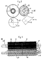
- This stripping roller 19 has on its surface a sharp-edged beads 21 with a sawtooth-shaped cross-section, as shown in FIG. 2 on an enlarged scale corresponding to section II from FIG. 1.
- these sawtooth-shaped beads 21 extend helically over the length of the stripping roller 19, as can be seen in FIG. 4.
- the sawtooth-shaped beads 21 each have a steep, almost radial front flank 22, a short tangential radial flank 23 and a flatter rear flank 24. Between the radial flank 23 and the rear flank 24 there is a soft rounded transition.
- the distance VI between the teeth 8 of the pulling roller 2 and the sawtooth beads 21 of the stripping roller 19 is only very small in order to peel off the skins and tendons from the pulling roller 2 by means of the stripping roller 19 in connection with its steep front flank 22.
- FIG. 3 the three-roll system with draw roller 2, cleaning roller 11 and stripping roller 19 compared to Fig. 1 is shown on an enlarged scale and on its own. This view corresponds to that view III in FIG. 4.
- the cleaning comb 14 with prongs 13 is shown here in the pivoted-out state.
- Fig. 4 the roller system is shown in side view, according to view IV in Fig. 3.
- the pull roller 2 is largely covered by the cleaning roller 11, so that only the upper area is visible.
- the ring grooves 12, which are distributed over the entire length of the cleaning roller 11 and into which the cleaning comb 14 engages with its prongs 13, can be clearly seen here.
- the tines 13 are shown as thicker lines for better visibility.
- the scraper roller 19 is also partially covered, namely here by the axis 15 of the cleaning comb 14.
- the helical sawtooth-shaped beads 21 can be seen on the scraper roller 19.
Landscapes
- Life Sciences & Earth Sciences (AREA)
- Engineering & Computer Science (AREA)
- Wood Science & Technology (AREA)
- Zoology (AREA)
- Food Science & Technology (AREA)
- Apparatuses For Bulk Treatment Of Fruits And Vegetables And Apparatuses For Preparing Feeds (AREA)
- Processing Of Meat And Fish (AREA)
- Bridges Or Land Bridges (AREA)
- Control And Other Processes For Unpacking Of Materials (AREA)
- Massaging Devices (AREA)
Claims (8)
- Machine à écorcher et à découenner- avec un plateau de table (4) porté par un bâti de machine (1), pour l'acheminement de la chair devant être écorchée,- avec un rouleau de traction (2) associé au plateau de table (4), dont la surface a une denture longitudinale (8), transversale par rapport au sens de rotation (I) des rouleaux, pour le transport de la chair,- avec une lame de coupe (3) tangente au rouleau de traction (2) et opposée à la direction de transport de la chair,- avec une barre porte-lame (5) portant la lame de coupe (3) et ayant une surface creuse (7) qui se trouve à une certaine distance de la surface du rouleau de traction et sert à guider le transport de la peau,- avec un rouleau de nettoyage (11) dont la surface présente une denture longitudinale (9) qui correspond à la denture (8) du rouleau de traction et peigne la denture du rouleau de traction (2),- avec des rainures annulaires (2) disposées sur la surface du rouleau de nettoyage (11), dans lesquelles un peigne de nettoyage (14) enfonce ses dents (13) pour nettoyer la surface du rouleau,
caractérisée par le fait- que seul le rouleau de traction est conçu sans rainures annulaires sur la surface,- qu'un rouleau racleur (19) a été prévu parallèlement au rouleau de traction (2), le rouleau racleur agissant ensemble avec ce dernier et ayant le même sens de rotation (I),- que le rouleau racleur, vu dans le sens de rotation du rouleau de traction (2), est placé en amont du rouleau de nettoyage (11) et près du rouleau de traction (2),- et qu'il y a sur la surface du rouleau racleur (19) des renflements (21) à arêtes vives. - Machine à écorcher et à découenner selon la revendication 1, caractérisée par le fait que les renflements à arêtes vives (21) ont sur la surface du rouleau racleur (19) un parcours légèrement hélicoïdal.
- Machine à écorcher et à découenner selon la revendication 1 ou 2, caractérisée par le fait que les renflements à arêtes vives (21) sur la surface du rouleau racleur (19) ont une coupe transversale en dents de scie, avec un flanc frontal raide dans le sens de la rotation (I), un flanc radial tangentiel court et un flanc arrière d'un tracé plus plat.
- Machine à écorcher et à découenner selon une des revendication précédentes, caractérisée par le fait que le rouleau de nettoyage (11) peut être déplacé ou pivoté à l'aide d'un dispositif et qu'il peut donc être séparé du rouleau de traction (2).
- Machine à écorcher et à découenner selon une des revendication précédentes, caractérisée par le fait que le peigne de nettoyage (14) peut être déplacé ou pivoté par rapport au rouleau de nettoyage (11) pour le faire rentrer ou sortir.
- Machine à écorcher et à découenner selon une des revendication précédentes, caractérisée par le fait que le rouleau de nettoyage (11) et le peigne de nettoyage (14) sont disposés sur un dispositif de support de la table (16), pouvant être pivoté avec le plateau de table (4), permettant ainsi en position pivotée de séparer le rouleau de nettoyage (11) du rouleau de traction (2).
- Machine à écorcher et à découenner selon la revendication 6, caractérisée par le fait que le palier de pivotement (15) est disposé sur le dispositif de support de la table (16).
- Machine à écorcher et à découenner selon une des revendication précédentes, caractérisée par le fait que le plateau de table (4) peut être retiré ou enlevé dans le sens opposé à la direction de transport de la chair.
Applications Claiming Priority (3)
| Application Number | Priority Date | Filing Date | Title |
|---|---|---|---|
| DE4121282 | 1991-06-27 | ||
| DE4121282A DE4121282C2 (de) | 1991-06-27 | 1991-06-27 | Enthäutungs- und Abschwartmaschine |
| PCT/DE1992/000532 WO1993000014A1 (fr) | 1991-06-27 | 1992-06-26 | Machine a ecorcher et a decouenner |
Publications (2)
| Publication Number | Publication Date |
|---|---|
| EP0591354A1 EP0591354A1 (fr) | 1994-04-13 |
| EP0591354B1 true EP0591354B1 (fr) | 1997-09-03 |
Family
ID=6434898
Family Applications (1)
| Application Number | Title | Priority Date | Filing Date |
|---|---|---|---|
| EP92913678A Expired - Lifetime EP0591354B1 (fr) | 1991-06-27 | 1992-06-26 | Machine a ecorcher et a decouenner |
Country Status (7)
| Country | Link |
|---|---|
| US (1) | US5533927A (fr) |
| EP (1) | EP0591354B1 (fr) |
| AT (1) | ATE157506T1 (fr) |
| DE (2) | DE4121282C2 (fr) |
| DK (1) | DK0591354T3 (fr) |
| ES (1) | ES2108755T3 (fr) |
| WO (1) | WO1993000014A1 (fr) |
Families Citing this family (6)
| Publication number | Priority date | Publication date | Assignee | Title |
|---|---|---|---|---|
| DE4227233A1 (de) * | 1992-08-18 | 1994-02-24 | Schill Maja Masch | Enthäutungs- und Abschwartmaschine |
| US6264542B1 (en) * | 1999-10-12 | 2001-07-24 | Geno N. Gasbarro | Apparatus for skinning pieces of poultry product |
| US6699116B1 (en) * | 2002-11-13 | 2004-03-02 | Remington Holdings Ltd | Automated poultry thigh skinning and deboning apparatus |
| US8087978B2 (en) * | 2004-11-12 | 2012-01-03 | Stork Townsend Inc. | Method and apparatus for removing skin and fat from meat parts |
| US7241213B2 (en) | 2005-03-30 | 2007-07-10 | Stork Townsend, Inc. | Open top meat skinning device |
| US8187060B1 (en) * | 2011-05-17 | 2012-05-29 | Remington Holdings, Llc | Apparatus for skinning poultry products |
Family Cites Families (11)
| Publication number | Priority date | Publication date | Assignee | Title |
|---|---|---|---|---|
| DE1267133B (de) * | 1959-02-28 | 1968-04-25 | Schill Maja Masch | Abschwartmaschine mit einem mit einer Verstelleinrichtung versehenen Messerhalter |
| FR2086688A5 (en) * | 1970-04-06 | 1971-12-31 | Townsend Engineering Co | Meat skinning machine |
| FR2427789A1 (fr) * | 1978-06-08 | 1980-01-04 | Wittig Jacques | Machine eplucheuse de viande |
| DE2844241C2 (de) * | 1978-10-11 | 1980-03-06 | Nordischer Maschinenbau Rud. Baader Gmbh + Co Kg, 2400 Luebeck | Vorrichtung zum Enthäuten von Fischfilets |
| FR2451253A1 (fr) * | 1979-03-13 | 1980-10-10 | Fourmentin Pollet Sa Armement | Procede de nettoyage du cylindre d'appel d'une machine a trancher et machine mettant en oeuvre ce procede |
| US4338704A (en) * | 1979-10-11 | 1982-07-13 | Iowa Beef Processors, Inc. | Method for processing beef tongues |
| DE3126009C1 (de) * | 1981-07-01 | 1982-10-28 | Townsend Engineering Co., 50317 Des Moines, Ia. | Greifrolle für eine Enthäutungsmaschine |
| DE3409933A1 (de) * | 1984-03-17 | 1985-09-26 | Maja-Maschinenfabrik Hermann Schill Gmbh, 7640 Kehl | Schneidmaschine fuer fleisch od. dgl. behandlungsgut |
| FR2618367B1 (fr) * | 1987-07-21 | 1994-11-18 | Cresson Christian | Moyens en vue du decollement d'une tranche de produit d'un rouleau d'entrainement et machine a couper les aliments pourvue de ces moyens |
| DE3837181C2 (de) * | 1988-11-02 | 1999-08-12 | Maja Maschinenfabrik Herrmann | Enthäutungs- oder Abschwartmaschine |
| DE3910984C1 (fr) * | 1989-04-05 | 1990-08-02 | Nordischer Maschinenbau Rud. Baader Gmbh + Co Kg, 2400 Luebeck, De |
-
1991
- 1991-06-27 DE DE4121282A patent/DE4121282C2/de not_active Expired - Fee Related
-
1992
- 1992-06-26 DK DK92913678.6T patent/DK0591354T3/da active
- 1992-06-26 DE DE59208864T patent/DE59208864D1/de not_active Expired - Lifetime
- 1992-06-26 AT AT92913678T patent/ATE157506T1/de not_active IP Right Cessation
- 1992-06-26 WO PCT/DE1992/000532 patent/WO1993000014A1/fr active IP Right Grant
- 1992-06-26 US US08/167,972 patent/US5533927A/en not_active Expired - Lifetime
- 1992-06-26 ES ES92913678T patent/ES2108755T3/es not_active Expired - Lifetime
- 1992-06-26 EP EP92913678A patent/EP0591354B1/fr not_active Expired - Lifetime
Also Published As
| Publication number | Publication date |
|---|---|
| DK0591354T3 (da) | 1998-04-20 |
| WO1993000014A1 (fr) | 1993-01-07 |
| DE59208864D1 (de) | 1997-10-09 |
| US5533927A (en) | 1996-07-09 |
| DE4121282C2 (de) | 2000-12-21 |
| DE4121282A1 (de) | 1993-01-07 |
| EP0591354A1 (fr) | 1994-04-13 |
| ES2108755T3 (es) | 1998-01-01 |
| ATE157506T1 (de) | 1997-09-15 |
Similar Documents
| Publication | Publication Date | Title |
|---|---|---|
| DE3311331C2 (de) | Abstreifersystem für die Schneid- oder Reißwalzen von Aktenvernichtern | |
| DE4024060C2 (fr) | ||
| DE3516623C2 (fr) | ||
| EP0591354B1 (fr) | Machine a ecorcher et a decouenner | |
| EP1066430B1 (fr) | Grille de criblage rotative | |
| WO2004048654A1 (fr) | Garniture integralement en acier destinee a des cylindres et/ou des tambours de cardes ou de cardeuses | |
| DE20301354U1 (de) | Zerkleinerungsvorrichtung | |
| DE69612708T2 (de) | Filtervorrichtung für eine Zitronensaftextraktionsmaschine und Konfiguration eines Perforator-Filterrohres für die Extraktion von Früchtensäften | |
| DE2412461C3 (de) | Feldhäcksler | |
| DE2927334A1 (de) | Schneidvorrichtung fuer landwirtschaftliche erntemaschinen | |
| DE1432502A1 (de) | Vorrichtung zum Raffen von Wursthuellen | |
| DE930855C (de) | Maschine zum Enthaeuten von Fleisch | |
| DE2250087A1 (de) | Sicherheitsvorrichtung fuer enthaeutungs- oder entschwartungsmaschinen | |
| DE2439235C3 (de) | Waschvorrichtung für Fahrzeuge | |
| DE3323659A1 (de) | Fuellmaschine fuer teigige medien, insbesondere fuer wurtstbraet | |
| DE3518341A1 (de) | Maschine zum entschwarten oder enthaeuten von fleisch oder fisch | |
| DE2811738A1 (de) | Haushalt-schneidmaschine | |
| DE3238255C2 (de) | Dermatom | |
| DE3409933A1 (de) | Schneidmaschine fuer fleisch od. dgl. behandlungsgut | |
| DE10241334B4 (de) | Luftreinigungsvorrichtung für Abschwartungs-, Enthäutungs- und/oder Entvliesmaschinen | |
| AT392872B (de) | Maishaecksler | |
| DE4203125A1 (de) | Haecksler und seine verwendung | |
| DE3805300A1 (de) | Verfahren und vorrichtung zum abtragen von wenigstens unter lagerdruck zusammengepresstem futtergut | |
| DE4227233A1 (de) | Enthäutungs- und Abschwartmaschine | |
| DE1756399A1 (de) | Vorrichtung zum Entnehmen von Silagegut |
Legal Events
| Date | Code | Title | Description |
|---|---|---|---|
| PUAI | Public reference made under article 153(3) epc to a published international application that has entered the european phase |
Free format text: ORIGINAL CODE: 0009012 |
|
| AK | Designated contracting states |
Kind code of ref document: A1 Designated state(s): AT BE CH DE DK ES FR GB GR IT LI MC NL SE |
|
| 17P | Request for examination filed |
Effective date: 19940125 |
|
| RBV | Designated contracting states (corrected) |
Designated state(s): AT BE CH DE DK ES FR GB IT LI NL SE |
|
| 17Q | First examination report despatched |
Effective date: 19950926 |
|
| GRAG | Despatch of communication of intention to grant |
Free format text: ORIGINAL CODE: EPIDOS AGRA |
|
| GRAH | Despatch of communication of intention to grant a patent |
Free format text: ORIGINAL CODE: EPIDOS IGRA |
|
| GRAH | Despatch of communication of intention to grant a patent |
Free format text: ORIGINAL CODE: EPIDOS IGRA |
|
| GRAA | (expected) grant |
Free format text: ORIGINAL CODE: 0009210 |
|
| STAA | Information on the status of an ep patent application or granted ep patent |
Free format text: STATUS: THE PATENT HAS BEEN GRANTED |
|
| AK | Designated contracting states |
Kind code of ref document: B1 Designated state(s): AT BE CH DE DK ES FR GB IT LI NL SE |
|
| REF | Corresponds to: |
Ref document number: 157506 Country of ref document: AT Date of ref document: 19970915 Kind code of ref document: T |
|
| REG | Reference to a national code |
Ref country code: CH Ref legal event code: EP |
|
| REF | Corresponds to: |
Ref document number: 59208864 Country of ref document: DE Date of ref document: 19971009 |
|
| ITF | It: translation for a ep patent filed | ||
| REG | Reference to a national code |
Ref country code: CH Ref legal event code: NV Representative=s name: PATENTANWALTSBUREAU R. A. MASPOLI |
|
| GBT | Gb: translation of ep patent filed (gb section 77(6)(a)/1977) |
Effective date: 19971201 |
|
| REG | Reference to a national code |
Ref country code: ES Ref legal event code: FG2A Ref document number: 2108755 Country of ref document: ES Kind code of ref document: T3 |
|
| ET | Fr: translation filed | ||
| REG | Reference to a national code |
Ref country code: DK Ref legal event code: T3 |
|
| PGFP | Annual fee paid to national office [announced via postgrant information from national office to epo] |
Ref country code: AT Payment date: 19980623 Year of fee payment: 7 |
|
| PLBE | No opposition filed within time limit |
Free format text: ORIGINAL CODE: 0009261 |
|
| 26N | No opposition filed | ||
| PG25 | Lapsed in a contracting state [announced via postgrant information from national office to epo] |
Ref country code: AT Free format text: LAPSE BECAUSE OF NON-PAYMENT OF DUE FEES Effective date: 19990626 |
|
| REG | Reference to a national code |
Ref country code: GB Ref legal event code: IF02 |
|
| PGFP | Annual fee paid to national office [announced via postgrant information from national office to epo] |
Ref country code: DK Payment date: 20020620 Year of fee payment: 11 |
|
| PGFP | Annual fee paid to national office [announced via postgrant information from national office to epo] |
Ref country code: CH Payment date: 20020621 Year of fee payment: 11 |
|
| PGFP | Annual fee paid to national office [announced via postgrant information from national office to epo] |
Ref country code: SE Payment date: 20020624 Year of fee payment: 11 |
|
| PGFP | Annual fee paid to national office [announced via postgrant information from national office to epo] |
Ref country code: ES Payment date: 20020625 Year of fee payment: 11 |
|
| PG25 | Lapsed in a contracting state [announced via postgrant information from national office to epo] |
Ref country code: SE Free format text: LAPSE BECAUSE OF NON-PAYMENT OF DUE FEES Effective date: 20030627 Ref country code: ES Free format text: LAPSE BECAUSE OF NON-PAYMENT OF DUE FEES Effective date: 20030627 |
|
| PG25 | Lapsed in a contracting state [announced via postgrant information from national office to epo] |
Ref country code: LI Free format text: LAPSE BECAUSE OF NON-PAYMENT OF DUE FEES Effective date: 20030630 Ref country code: DK Free format text: LAPSE BECAUSE OF NON-PAYMENT OF DUE FEES Effective date: 20030630 Ref country code: CH Free format text: LAPSE BECAUSE OF NON-PAYMENT OF DUE FEES Effective date: 20030630 |
|
| EUG | Se: european patent has lapsed | ||
| REG | Reference to a national code |
Ref country code: DK Ref legal event code: EBP |
|
| REG | Reference to a national code |
Ref country code: CH Ref legal event code: PL |
|
| REG | Reference to a national code |
Ref country code: ES Ref legal event code: FD2A Effective date: 20030627 |
|
| PGFP | Annual fee paid to national office [announced via postgrant information from national office to epo] |
Ref country code: GB Payment date: 20080606 Year of fee payment: 17 |
|
| GBPC | Gb: european patent ceased through non-payment of renewal fee |
Effective date: 20090626 |
|
| PG25 | Lapsed in a contracting state [announced via postgrant information from national office to epo] |
Ref country code: GB Free format text: LAPSE BECAUSE OF NON-PAYMENT OF DUE FEES Effective date: 20090626 |
|
| PGFP | Annual fee paid to national office [announced via postgrant information from national office to epo] |
Ref country code: NL Payment date: 20100629 Year of fee payment: 19 |
|
| PGFP | Annual fee paid to national office [announced via postgrant information from national office to epo] |
Ref country code: IT Payment date: 20100630 Year of fee payment: 19 Ref country code: FR Payment date: 20100720 Year of fee payment: 19 Ref country code: DE Payment date: 20100713 Year of fee payment: 19 |
|
| PGFP | Annual fee paid to national office [announced via postgrant information from national office to epo] |
Ref country code: BE Payment date: 20100727 Year of fee payment: 19 |
|
| BERE | Be: lapsed |
Owner name: MAJA-MASCHINENFABRIK HERMANN *SCHILL G.M.B.H. Effective date: 20110630 |
|
| REG | Reference to a national code |
Ref country code: NL Ref legal event code: V1 Effective date: 20120101 |
|
| PG25 | Lapsed in a contracting state [announced via postgrant information from national office to epo] |
Ref country code: IT Free format text: LAPSE BECAUSE OF NON-PAYMENT OF DUE FEES Effective date: 20110626 |
|
| REG | Reference to a national code |
Ref country code: FR Ref legal event code: ST Effective date: 20120229 |
|
| PG25 | Lapsed in a contracting state [announced via postgrant information from national office to epo] |
Ref country code: BE Free format text: LAPSE BECAUSE OF NON-PAYMENT OF DUE FEES Effective date: 20110630 |
|
| REG | Reference to a national code |
Ref country code: DE Ref legal event code: R119 Ref document number: 59208864 Country of ref document: DE Effective date: 20120103 |
|
| PG25 | Lapsed in a contracting state [announced via postgrant information from national office to epo] |
Ref country code: FR Free format text: LAPSE BECAUSE OF NON-PAYMENT OF DUE FEES Effective date: 20110630 Ref country code: DE Free format text: LAPSE BECAUSE OF NON-PAYMENT OF DUE FEES Effective date: 20120103 |
|
| PG25 | Lapsed in a contracting state [announced via postgrant information from national office to epo] |
Ref country code: NL Free format text: LAPSE BECAUSE OF NON-PAYMENT OF DUE FEES Effective date: 20120101 |