EP0591354B1 - Flaying and skinning machine - Google Patents
Flaying and skinning machine Download PDFInfo
- Publication number
- EP0591354B1 EP0591354B1 EP92913678A EP92913678A EP0591354B1 EP 0591354 B1 EP0591354 B1 EP 0591354B1 EP 92913678 A EP92913678 A EP 92913678A EP 92913678 A EP92913678 A EP 92913678A EP 0591354 B1 EP0591354 B1 EP 0591354B1
- Authority
- EP
- European Patent Office
- Prior art keywords
- roller
- cleaning
- flaying
- skinning machine
- machine according
- Prior art date
- Legal status (The legal status is an assumption and is not a legal conclusion. Google has not performed a legal analysis and makes no representation as to the accuracy of the status listed.)
- Expired - Lifetime
Links
- 238000004140 cleaning Methods 0.000 claims abstract description 53
- 235000013372 meat Nutrition 0.000 claims description 8
- 238000009966 trimming Methods 0.000 abstract 1
- 239000011324 bead Substances 0.000 description 8
- 239000004519 grease Substances 0.000 description 3
- 239000000463 material Substances 0.000 description 3
- 239000011888 foil Substances 0.000 description 2
- 210000002435 tendon Anatomy 0.000 description 2
- 241000283690 Bos taurus Species 0.000 description 1
- 230000001427 coherent effect Effects 0.000 description 1
- 230000007547 defect Effects 0.000 description 1
- 230000006866 deterioration Effects 0.000 description 1
- 230000000694 effects Effects 0.000 description 1
- 239000010419 fine particle Substances 0.000 description 1
- 230000003993 interaction Effects 0.000 description 1
- 239000002245 particle Substances 0.000 description 1
- 230000007704 transition Effects 0.000 description 1
Images

Classifications
-
- A—HUMAN NECESSITIES
- A22—BUTCHERING; MEAT TREATMENT; PROCESSING POULTRY OR FISH
- A22C—PROCESSING MEAT, POULTRY, OR FISH
- A22C17/00—Other devices for processing meat or bones
- A22C17/12—Apparatus for cutting-off rind
Definitions
- the invention relates to a skinning and chilling machine according to the preamble of the main claim.
- a device corresponding to the preamble of claim 1 is known from FR-A-24 27 789.
- a further known generic skinning and shedding machine (DE-OS 38 37 181), good skinning is achieved by the interaction of the surface teeth of the traction roller, the cutting blade but also the blade bar arranged at a certain distance from its hollow surface.
- annular grooves are arranged on the pulling roller, which engage the teeth of a cleaning comb for cleaning the pulling roller surface.
- the toothing surface is reduced by the surface stressed by the ring grooves.
- the skinning efficiency is correspondingly reduced, since the traction roller essentially takes on the feed function when skinning.
- a cleaning roller is used for cleaning grease and less connected parts, the teeth of which correspond to those of the pulling roller and the two teeth mesh with one another, so that the longitudinal teeth of the surface of the pulling roller existing particles similar to a defect, especially squeezed out into the ring grooves.
- the cleaning roller is arranged downstream of the cleaning comb in the direction of rotation of the pull roller.
- the cleaning comb removes the essential parts of the skin, the meshing of the teeth of the pulling roller and cleaning roller forms grease and tissue foils in some types of meat, which are pressed onto the surface of the cleaning roller and impair its cleaning function on the pulling roller.
- a stripping roller interacts with the pulling roller, the surface of which is also toothed without this toothing engaging in that of the pulling roller and wherein the pulling roller and stripping roller have the same direction of rotation, so that they are close to one another opposite surfaces of the pulling roller and stripping roller, a high relative speed arises.
- the stripping roller takes over the separated skin and tissue parts to a sufficient extent.
- fat and fine materials cannot be removed by this, so that in addition, a blower is used to blow such parts away from the surface of the draw roller with all the disadvantages.
- the skinning and skimming machine according to the invention with the characterizing features of the main claim has the advantage that the pulling roller has the entire surface available for the skinning task, since ring grooves are no longer required.
- the stripping roller known per se in the arrangement the coherent pieces such as skin and tissue parts are removed from the surface of the pull roller.
- the toothing of the downstream cleaning roller then engages in that of the surface of the pull roller and presses out any grease and fine particles there.
- the cleaning comb engaging on this surface removes foils from the surface of the cleaning roller, so that it engages with largely cleaned teeth in the dirty pull roller.
- the ring grooves cause only an insignificant deterioration in the cleaning effect.
- the overall efficiency of the inventive skinning and skimming machine is significantly improved compared to the known machines.
- the sharp-edged beads run helically on the surface of the stripping roller.
- a helical arrangement is known per se from the above-mentioned machine (FR-PS 70 12 414).
- the slightly helical course makes it easier to peel off the skins from the pull roller, since peeling begins on one side of the roller and then spreads to the length of the roller.
- the sharp-edged beads on the stripper roller have a sawtooth-shaped cross section with a steep front flank pointing in the direction of rotation, a short tangential radial flank and a flatter running rear flank that ends radially on the inside on the subsequent front flank.
- This sawtooth-shaped design and in connection with the only slight distance of the tangential radial flank section of these beads from the surface, or the toothing of the pulling roller prevents the skin and tissue parts to be peeled off from the pulling roller from getting between the two rollers.
- the stripping roller can run in a manner known per se (FR-PS 70 12 414) at a higher speed than the pull roller.
- the cleaning roller and / or the cleaning comb can be displaced and / or swung out in order to be able to clean the machine better as a result.
- the cleaning roller and / or the cleaning comb are arranged on a table support device which can be pivoted with the table top, whereby the cleaning roller is separated from the pull roller in the pivoting position of the table support device.
- the table support device is mounted on the machine housing with its swivel arrangement in a manner known per se (DE-OS 38 37 181).
- the table top can be retracted or pulled out against the direction of meat transport in order to easily reach the rollers from above.
- the blade bar with cutting blade can be arranged on a swiveling device which is also mounted on the machine housing or, correspondingly, the pull roller or the stripping roller.
- the cleaning comb can be pivoted relative to the cleaning roller for its engagement and disengagement in a manner known per se, the pivot bearing being arranged on the table support device.
- the cleaning comb can also be pivoted out independently of the pivoting of the table top. Because the cleaning comb can be arranged on the side of the cleaning roller facing away from the pulling roller due to the direction of rotation of the cleaning roller (opposite to that of the pulling roller), there is good accessibility; in any case much better than in the known skinning machine (DE-OS 38 37 181).
- a pull roller 2 is mounted in a housing 1, which is driven in the direction of rotation I by means not shown and which cooperates with a cutting blade 3 to meat Skin or wait, which is fed manually via a table top 4 in the direction of the cutting blade 3.
- the cutting blade 3 is clamped to a blade bar 5 by a holding bar 6.
- the blade bar 5 has a barrel-shaped hollow surface 7 towards the pulling roller 2, this distance between the hollow surface 7 and the surface of the pulling roller 2 being important for the transport of the skins removed from the meat.
- toothing 8 arranged on the surface of the pulling roller 2 by means of the skins or, due to the direction of rotation I of the pulling roller, the skins or Tendons and rinds are pulled past the cutting blade 3.
- the tooth flanks of this toothing 8, which extend over the length of the pulling roller 2, are straight and relatively steep.
- this toothing 8 of the pull roller 2 meshes a toothing 9 on the surface of a cleaning roller 11, this toothing also extends to the length of the cleaning roller 11, but is interrupted by annular grooves 12 into which the prongs 13 of a cleaning comb 14 engage. In this way, material transferred from the pull roller 2 to the cleaning roller 11 and compressed there is combed out, since such material is largely displaced into the annular grooves when the teeth 8 and 9 mesh.
- the cleaning comb 14 is mounted on an axis 15 and can be pivoted out as shown in FIG. 3.
- the axis 15 is in turn arranged on a table support device 16 mounted in the housing 1, on which the table top 4 is arranged and the cleaning roller 11 is mounted and which can be pivoted about an axis 17 mounted in the housing 1, for example in the dash-dotted line in FIG. 1 Swivel position. In this swiveling position there is good access to the pull roller 2 and cleaning roller 11, for example in order to be able to clean the machine.
- the table support device 16 is held in the respective pivot position by a latch 18.
- a stripper roller 19 is also mounted, which is driven in the same direction of rotation I as the pull roller 2, preferably at a higher speed.
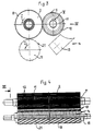
- This stripping roller 19 has on its surface a sharp-edged beads 21 with a sawtooth-shaped cross-section, as shown in FIG. 2 on an enlarged scale corresponding to section II from FIG. 1.
- these sawtooth-shaped beads 21 extend helically over the length of the stripping roller 19, as can be seen in FIG. 4.
- the sawtooth-shaped beads 21 each have a steep, almost radial front flank 22, a short tangential radial flank 23 and a flatter rear flank 24. Between the radial flank 23 and the rear flank 24 there is a soft rounded transition.
- the distance VI between the teeth 8 of the pulling roller 2 and the sawtooth beads 21 of the stripping roller 19 is only very small in order to peel off the skins and tendons from the pulling roller 2 by means of the stripping roller 19 in connection with its steep front flank 22.
- FIG. 3 the three-roll system with draw roller 2, cleaning roller 11 and stripping roller 19 compared to Fig. 1 is shown on an enlarged scale and on its own. This view corresponds to that view III in FIG. 4.
- the cleaning comb 14 with prongs 13 is shown here in the pivoted-out state.
- Fig. 4 the roller system is shown in side view, according to view IV in Fig. 3.
- the pull roller 2 is largely covered by the cleaning roller 11, so that only the upper area is visible.
- the ring grooves 12, which are distributed over the entire length of the cleaning roller 11 and into which the cleaning comb 14 engages with its prongs 13, can be clearly seen here.
- the tines 13 are shown as thicker lines for better visibility.
- the scraper roller 19 is also partially covered, namely here by the axis 15 of the cleaning comb 14.
- the helical sawtooth-shaped beads 21 can be seen on the scraper roller 19.
Landscapes
- Life Sciences & Earth Sciences (AREA)
- Engineering & Computer Science (AREA)
- Wood Science & Technology (AREA)
- Zoology (AREA)
- Food Science & Technology (AREA)
- Apparatuses For Bulk Treatment Of Fruits And Vegetables And Apparatuses For Preparing Feeds (AREA)
- Processing Of Meat And Fish (AREA)
- Bridges Or Land Bridges (AREA)
- Control And Other Processes For Unpacking Of Materials (AREA)
- Massaging Devices (AREA)
Abstract
Description
Die Erfindung geht aus von einer Enthäutungs- und Abschwartmaschine nach der Gattung des Hauptanspruchs. Eine dem Oberbegriff von Anspruch 1 entsprechende Vorrichtung ist aus FR-A-24 27 789 bekannt. Bei einer weiteren bekannten gattungsgemäßen Enthäutungs- und Abschwartmaschine (DE-OS 38 37 181) wird durch das Zusammenwirken von der Oberflächenverzahnung der Zugwalze, der Schneidklinge aber auch dem mit bestimmtem Abstand seiner Hohlfläche angeordneten Klingenbalken eine gute Enthäutung erzielt. Bei dieser bekannten Maschine sind auf der Zugwalze jedoch Ringnuten angeordnet in die zur Reinigung der Zugwalzenoberfläche Zinken eines Reinigungskammes greifen. Konstruktionsbedingt ist dadurch die Verzahnungsoberfläche um die durch die Ringnuten beanspruchte Oberfläche verringert.The invention relates to a skinning and chilling machine according to the preamble of the main claim. A device corresponding to the preamble of
Entsprechend ist auch der Wirkungsgrad beim Enthäuten verringert, da die Zugwalze im wesentlichen die Vorschubfunktion beim Enthäuten übernimmt. Während der Reinigungskamm bei dieser bekannten Maschine im wesentlichen Haut- und Gewebeteile von der Zugwalzenoberfläche entfernt, dient zur Reiniung von Fett und weniger zusammenhängenden Teilen eine Reinigungswalze, deren Verzahnung jener der Zugwalze entspricht und wobei beide Verzahnungen ineinander greifen, so daß in der Längsverzahnung der Zugwalzenoberfläche vorhandene Teilchen ähnlich wie bei einer Mangel, insbesondere in die Ringnuten herausgequetscht werden. Die Reinigungswalze ist in Drehrichtung der Zugwalze dem Reiniungskamm nachgeschaltet. Obwohl der Reinigungskamm die wesentlichen Hautteile entfernt, werden durch das Kämmen der Verzahnungen von Zugwalze und Reinigungswalze bei manchen Fleischarten Fett- und Gewebefolien gebildet, die auf der Oberfläche der Reinigungswalze festgepreßt sind und deren Reinigungsfunktion an der Zugwalze beeinträchtigen.The skinning efficiency is correspondingly reduced, since the traction roller essentially takes on the feed function when skinning. While the cleaning comb in this known machine essentially removes skin and tissue parts from the surface of the pulling roller, a cleaning roller is used for cleaning grease and less connected parts, the teeth of which correspond to those of the pulling roller and the two teeth mesh with one another, so that the longitudinal teeth of the surface of the pulling roller existing particles similar to a defect, especially squeezed out into the ring grooves. The cleaning roller is arranged downstream of the cleaning comb in the direction of rotation of the pull roller. Although the cleaning comb removes the essential parts of the skin, the meshing of the teeth of the pulling roller and cleaning roller forms grease and tissue foils in some types of meat, which are pressed onto the surface of the cleaning roller and impair its cleaning function on the pulling roller.
Bei einer anderen bekannten Enthäutungsmaschine (FR 70 12 414) wirkt mit der Zugwalze eine Abstreifwalze zusammen, deren Oberfläche ebenfalls verzahnt ist, ohne daß diese Verzahnung in jene der Zugwalze greift und wobei Zugwalze und Abstreifwalze die gleiche Drehrichtung aufweisen, so daß an den nahe einander gegenüberliegenden Oberflächen von Zugwalze und Abstreifwalze eine hohe Relativgeschwindigkeit entsteht. Die Abstreifwalze übernimmt die abgetrennten Haut- und Gewebeteile in ausreichendem Maße. Nicht jedoch können Fett- und Feinmaterialien hierdurch entfernt werden, so daß zusätzlich ein Gebläse eingesetzt wird, um solche Teile von der Oberfläche der Zugwalze wegzublasen mit all den dabei gegebenen Nachteilen.In another known skinning machine (FR 70 12 414), a stripping roller interacts with the pulling roller, the surface of which is also toothed without this toothing engaging in that of the pulling roller and wherein the pulling roller and stripping roller have the same direction of rotation, so that they are close to one another opposite surfaces of the pulling roller and stripping roller, a high relative speed arises. The stripping roller takes over the separated skin and tissue parts to a sufficient extent. However, fat and fine materials cannot be removed by this, so that in addition, a blower is used to blow such parts away from the surface of the draw roller with all the disadvantages.
Die erfindungsgemäße Enthäutungs- und Abschwartmaschine mit den kennzeichnenden Merkmalen des Hauptanspruchs hat demgegenüber den Vorteil, daß die Zugwalze für die Enthäutungsaufgabe die gesamte Oberfläche zur Verfügung hat, da keine Ringnuten mehr erforderlich sind. Durch die in der Anordnung ansich bekannte Abstreifwalze werden die zusammenhängenden Stücke wie Haut- und Gewebeteile von der Zugwalzenoberfläche entfernt. Die nachgeschaltete Reinigungswalze greift sodann mit ihrer Verzahnung in jene der Zugwalzenoberfläche ein und preßt dort vorhandene Fett- und Feinteile heraus. Durch den an dieser Oberfläche eingreifenden Reinigungskamm werden sich dort bildende Folien von der Oberfläche der Reinigungswalze entfernt, so daß diese mit weitgehend gereinigten Zähnen in die verschmutzte Zugwalze eingreift. Auf der Reinigungswalze bewirken die Ringnuten nur eine unerhebliche Verschlechterung der Reinigungswirkung. Der Gesamtwirkungsgrad der erfinderischen Enthäutungs- und Abschwartmaschine ist jedoch gegenüber den bekannten Maschinen wesentlich verbessert.The skinning and skimming machine according to the invention with the characterizing features of the main claim has the advantage that the pulling roller has the entire surface available for the skinning task, since ring grooves are no longer required. By means of the stripping roller known per se in the arrangement, the coherent pieces such as skin and tissue parts are removed from the surface of the pull roller. The toothing of the downstream cleaning roller then engages in that of the surface of the pull roller and presses out any grease and fine particles there. The cleaning comb engaging on this surface removes foils from the surface of the cleaning roller, so that it engages with largely cleaned teeth in the dirty pull roller. On the cleaning roller, the ring grooves cause only an insignificant deterioration in the cleaning effect. However, the overall efficiency of the inventive skinning and skimming machine is significantly improved compared to the known machines.
Nach einer vorteilhaften Ausgestaltung der Erfindung verlaufen die scharfkantigen Wülste auf der Oberfläche der Abstreifwalze schraubenförmig. Eine solche schraubenförmige Anordnung ist ansich bekannt durch die oben genannte Maschine (FR-PS 70 12 414). Durch den leicht schraubenförmigen Verlauf wird das Abpellen der Häute von der Zugwalze erleichtert, da daß Abpellen einseitig an der Walze beginnt, um sich dann auf die Länge der Walze auszubreiten.According to an advantageous embodiment of the invention, the sharp-edged beads run helically on the surface of the stripping roller. Such a helical arrangement is known per se from the above-mentioned machine (FR-PS 70 12 414). The slightly helical course makes it easier to peel off the skins from the pull roller, since peeling begins on one side of the roller and then spreads to the length of the roller.
Nach einer weiteren vorteilhaften Ausgestaltung der Erfindung weisen die scharfkantigen Wülste auf der Abstreifwalze einen sägezahnförmigen Querschnitt auf mit einer in Drehrichtung weisenden steilen Frontflanke, einer kurzen tangentialen Radialflanke und einer flacher verlaufenden Rückseitenflanke, die radial innen an der nachfolgenden Frontflanke endet. Durch diese sägezahnförmige Gestaltung und in Verbindung mit dem nur geringen Abstand des tangentialen Radialflankenabschnitts dieser Wülste zur Oberfläche, bzw. zur Verzahnung der Zugwalze hin wird vermieden, daß die von der Zugwalze abzupellenden Haut- und Gewebeteile zwischen die beiden Walzen gelangen. Vorzugsweise kann die Abstreifwalze in ansich bekannter Weise (FR-PS 70 12 414) mit einer höheren Drehzahl laufen als die Zugwalze.According to a further advantageous embodiment of the invention, the sharp-edged beads on the stripper roller have a sawtooth-shaped cross section with a steep front flank pointing in the direction of rotation, a short tangential radial flank and a flatter running rear flank that ends radially on the inside on the subsequent front flank. This sawtooth-shaped design and in connection with the only slight distance of the tangential radial flank section of these beads from the surface, or the toothing of the pulling roller, prevents the skin and tissue parts to be peeled off from the pulling roller from getting between the two rollers. Preferably, the stripping roller can run in a manner known per se (FR-PS 70 12 414) at a higher speed than the pull roller.
Nach einer weiteren vorteilhaften Ausgestaltung der Erfindung können die Reinigungswalze und/oder der Reinigungskamm verschiebbar und/oder ausschwenkbar sein, um dadurch die Maschine besser reinigen zu können. So ist es gemäß der Erfindung möglich, daß die Reinigungswalze und/oder der Reinigungskamm auf einer mit der Tischplatte verschwenkbaren Tischtragevorrichtung angeordnet, wodurch in Ausschwenkstellung der Tischtragevorrichtung die Reinigungswalze von der Zugwalze getrennt ist. Die Tischtragevorrichtung ist mit ihrer Schwenkanordnung in ansich bekannter Weise (DE-OS 38 37 181) an dem Maschinengehäuse gelagert.According to a further advantageous embodiment of the invention, the cleaning roller and / or the cleaning comb can be displaced and / or swung out in order to be able to clean the machine better as a result. Thus, it is possible according to the invention that the cleaning roller and / or the cleaning comb are arranged on a table support device which can be pivoted with the table top, whereby the cleaning roller is separated from the pull roller in the pivoting position of the table support device. The table support device is mounted on the machine housing with its swivel arrangement in a manner known per se (DE-OS 38 37 181).
Nach einer vorteilhaften Ausgestaltung der Erfindung ist die Tischplatte entgegen der Fleischtransportrichtung zurück- bzw. herausziehbar um in einfacher Weise von oben an die Walzen heranzukommen. Ebenfalls kann in ansich bekannter Weise der Klingenbalken mit Schneidklinge an einer Schwenkvorrichtung angeordnet sein, die ebenfalls am Maschinengehäuse gelagert ist oder auch entsprechend die Zugwalze oder die Abstreifwalze.According to an advantageous embodiment of the invention, the table top can be retracted or pulled out against the direction of meat transport in order to easily reach the rollers from above. Likewise, in a manner known per se, the blade bar with cutting blade can be arranged on a swiveling device which is also mounted on the machine housing or, correspondingly, the pull roller or the stripping roller.
Nach einer weiteren vorteilhaften Ausgestaltung der Erfindung ist der Reinigungskamm relativ zur Reinigungswalze für seinen Ein- und Ausgriff in ansich bekannter Weise verschwenkbar, wobei das Schwenklager an der Tischtragevorrichtung angeordnet ist. Die Ausschwenkung des Reinigungskamms kann erfindungsgemäß auch unabhängig von der Verschwenkung der Tischplatte erfolgen. Dadurch daß der Reinigungskamm aufgrund der Drehrichtung der Reinigungswalze (entgegengesetzt jener der Zugwalze) auf der der Zugwalze abgewandten Seite der Reinigungswalze angeordnet sein kann, besteht eine gute Zugänglichkeit; jedenfalls wesentlich besser als bei der bekannten Enthäutungsmaschine (DE-OS 38 37 181).According to a further advantageous embodiment of the invention, the cleaning comb can be pivoted relative to the cleaning roller for its engagement and disengagement in a manner known per se, the pivot bearing being arranged on the table support device. The cleaning comb can also be pivoted out independently of the pivoting of the table top. Because the cleaning comb can be arranged on the side of the cleaning roller facing away from the pulling roller due to the direction of rotation of the cleaning roller (opposite to that of the pulling roller), there is good accessibility; in any case much better than in the known skinning machine (DE-OS 38 37 181).
Weitere Vorteile und vorteilhafte Ausgestaltungen der Erfindung sind der nachfolgenden Beschreibung der Zeichnung und den Ansprüchen entnehmbar.Further advantages and advantageous embodiments of the invention can be found in the following description of the drawing and the claims.
Ein Ausführungsbeispiel des Gegenstandes der Erfindung ist in der Zeichnung dargestellt und im folgenden näher beschrieben. Es zeigen:
- Fig. 1
- eine vereinfachte Seitenansicht der wesentlichen Maschinenteile unter Weglassung der Seitenwand,
- Fig. 2
- eine Vergrößerung des Ausschnitts II aus Fig. 1,
- Fig. 3
- das Walzenwerk gemäß Ansicht III in Fig. IV und
- Fig. 4
- das Walzenwerk gemäß Ansicht IV in Fig. 3
- Fig. 1
- a simplified side view of the essential machine parts, omitting the side wall,
- Fig. 2
- an enlargement of section II from FIG. 1,
- Fig. 3
- the roller mill according to view III in Fig. IV and
- Fig. 4
- the roller mill according to view IV in Fig. 3rd
Bei der in Fig. 1 sehr vereinfacht und nur mit den wesentlichen Teilen gezeigten Enthäutungs- und Abschwartmaschine ist in einem Gehäuse 1 eine Zugwalze 2 gelagert, die in Drehrichtung I durch nicht dargestellte Mittel angetrieben wird und die mit einer Schneidklinge 3 zusammenwirkt, um Fleisch zu enthäuten oder abzuschwarten, welches über eine Tischplatte 4 manuell in Richtung Schneidklinge 3 zugeführt wird. Die Schneidklinge 3 ist an einem Klingenbalken 5 durch eine Halteleiste 6 festgespannt. Der Klingenbalken 5 weist zur Zugwalze 2 hin eine tonnenförmige Hohlfläche 7 auf, wobei dieser Abstand zwischen Hohlfläche 7 und Oberfläche der Zugwalze 2 für den Transport der vom Fleisch abgezogenen Häute von Bedeutung ist. Entscheidend jedoch ist für die Enthäutung die auf der Oberfläche der Zugwalze 2 angeordnete Verzahnung 8 mittels der, und aufgrund der Drehrichtung I der Zugwalze, die abzuziehenden Häute bzw. Sehnen und Schwarten an der Schneidklinge 3 vorbeigezogen werden. Die Zahnflanken dieser sich über die Länge der Zugwalze 2 erstreckenden Verzahnung 8 sind gradflächig und verhältnismäßig steil.In the very simplified in FIG. 1 and only with the essential parts skinning and skimming machine, a
Mit dieser Verzahnung 8 der Zugwalze 2 kämmt eine Verzahnung 9 auf der Oberfläche einer Reinigungswalze 11, wobei sich diese Verzahnung ebenfalls auf die Länge der Reinigungswalze 11 erstreckt, jedoch durch Ringnuten 12 unterbrochen ist in welche die Zinken 13 eines Reinigungskammes 14 greifen. Auf diese Weise wird sich von der Zugwalze 2 auf die Reinigungswalze 11 übertragenes und dort verdichtetes Material herausgekämmt, da bei dem Ineinandergreifen der Verzahnungen 8 und 9 solches Material weitgehend in die Ringnuten verdrängt wird. Der Reinigungskamm 14 ist auf einer Achse 15 gelagert und kann wie in Fig. 3 dargestellt ausgeschwenkt werden. Die Achse 15 ist wiederum auf einer im Gehäuse 1 gelagerten Tischtragevorrichtung 16 angeordnet, auf der die Tischplatte 4 angeordnet ist und die Reinigungswalze 11 gelagert ist und welche um eine im Gehäuse 1 gelagerte Achse 17 schwenkbar ist, beispielsweise in die in Fig. 1 strichpunktiert dargestellte Ausschwenklage. In dieser Ausschwenklage besteht ein guter Zugang zu Zugwalze 2 und Reinigungswalze 11, beispielsweise um die Maschine reinigen zu können. Die Tischtragevorrichtung 16 wird durch einen Riegel 18 in der jeweiligen Schwenkstellung gehalten.With this toothing 8 of the
Im Gehäuse 1 ist als weiteres eine Abstreifwalze 19 gelagert, die in gleicher Drehrichtung I wie die Zugwalze 2 angetrieben ist, und zwar vorzugsweise mit einer höheren Drehzahl. Diese Abstreifwalze 19 weist auf ihrer Oberfläche eine scharfkantige Wülste 21 mit sägezahnförmigem Querschnitt auf, wie sie in Fig. 2 in vergrößerten Maßstab entsprechend dem Ausschnitt II aus Fig. 1 gezeigt ist. Zudem verlaufen diese sägezahnförmigen Wülste 21 schraubenförmig über die Länge der Abstreifwalze 19 so wie es Fig. 4 entnehmbar ist.In the
Die sägezahnförmigen Wülste 21 weisen jeweils eine steile, fast radial verlaufende Frontflanke 22 eine kurze tangentiale Radialflanke 23 und eine flacher verlaufende Rückseitenflanke 24 auf. Zwischen der Radialflanke 23 und der Rückseitenflanke 24 ist ein weicher abgerundeter Übergang. Der Abstand VI zwischen der Verzahnung 8 der Zugwalze 2 und den Sägezahnwülsten 21 der Abstreifwalze 19 ist nur sehr gering, um durch die Abstreifwalze 19 in Verbindung mit deren steilen Frontflanke 22 die Häute und Sehnen von der Zugwalze 2 abzupellen.The sawtooth-shaped
In Fig. 3 ist das Dreiwalzensystem mit Zugwalze 2, Reinigungswalze 11 und Abstreifwalze 19 gegenüber Fig. 1 in vergrößertem Maßstab und für sich allein dargestellt. Diese Ansicht entspricht jener Ansicht III in Fig. 4. Außerdem ist hier der Reinigungskamm 14 mit Zinken 13 in ausgeschwenktem Zustand dargestellt.In Fig. 3, the three-roll system with
In Fig. 4 ist das Walzensystem in der Seitenansicht dargestellt, gemäß Ansicht IV in Fig. 3. Die Zugwalze 2 ist weitgehend durch die Reinigungswalze 11 verdeckt, so daß nur der obere Bereich erkennbar ist. In der Reinigungswalze 11 sind hier deutlich erkennbar, und zwar auf die ganze Länge der Reinigungswalze 11 verteilt, die Ringnuten 12 angeordnet, in die der Reinigungskamm 14 mit seinen Zinken 13 greift. Zur besseren Erkennbarkeit sind die Zinken 13 als dickere Linien dargestellt. Auch die Abstreifwalze 19 ist teilweise verdeckt, und zwar hier durch die Achse 15 des Reinigungskamms 14. Auf der Abstreifwalze 19 sind die schraubenförmig verlaufenden sägezahnförmigen Wülste 21 erkennbar.In Fig. 4 the roller system is shown in side view, according to view IV in Fig. 3. The
Claims (8)
- Flaying and skinning machine- with a table plate (4), supported by a machine casing (1), for the supply of a piece of meat to be skinned,- with a feed roller (2), related to the table plate (4), whose surface is splined (8) transverse to the roller's diection of rotation (I) in order to feed the meat,- with a cutting blade (3) running tangentially to the feed roller (2) facing against the meat supply direction,- with a blade beam (5) bearing the cutting blade (3) and featuring a hollow surface (7) related to the feed roller surface by a certain distance, to guide the main supply,- with annular tee-slots (12) postitioned on the surface of the cleaning roller (11) into which a cleaning comb (14) engages with its teeth (13) to clean the roller surface,
characterized in that- only the feed roller is designed without annular tee-slots on ints surface- and that a stripping roller (19) is provided working in conjunction with and positioned parallel to the feed roller (2), turning with the same sense of rotation,- and that - seen in the sense of rotation of the feed roller (2) - the stripping roller is positioned before the cleaning roller (11) and near the feed roller (2)- and that sharp-edged elevations (21) are positioned on the surface of the stripping roller (19). - Flaying and skinning machine according to claim 1, characterized in that the sharp-edged elevations (21) on the stripping roller (19) run along the surface in light spirals.
- Flaying and skinning machine according to claim 1 or 2, characterized in that the sharp-edged elevations (21) on the surface of the stripping roller (19) are of saw-toothed cross-section with a steep front flank pointing in the direction of rotation (I), a short tangential radial flank, and a somewhat flatter back flank.
- Flaying and skinning machine according to one of the above claims, characterized in that the cleaning roller (11) can be shifted and tilted by an attachment, and thus separated from the feed foller (2).
- Flaying and skinning machine according to one of the above claims, characterized in that the cleaning comb (14) can be tilted and shifted relative to the cleaning roller (11) for engagement and disengagement.
- Flaying and skinning machine according to one of the above claims, characterized in that the cleaning roller (11) and the cleaning comb (14) are positioned on a table supporting device (16) that can be tilted relative to the table, thus allowing to separate the cleaning roller (11) from the feed roller (2) in tilted position.
- Flaying and skinning machine according to claim 6, characterized in that the tilting pivot (15) is attached to the table supporting device (16).
- Flaying and skinning machine according to one of the above claims, characterized in that the table plate (4) can be drawn back or out against the direction of meat supply.
Applications Claiming Priority (3)
| Application Number | Priority Date | Filing Date | Title |
|---|---|---|---|
| DE4121282 | 1991-06-27 | ||
| DE4121282A DE4121282C2 (en) | 1991-06-27 | 1991-06-27 | Skinning and decoating machine |
| PCT/DE1992/000532 WO1993000014A1 (en) | 1991-06-27 | 1992-06-26 | Flaying and skinning machine |
Publications (2)
| Publication Number | Publication Date |
|---|---|
| EP0591354A1 EP0591354A1 (en) | 1994-04-13 |
| EP0591354B1 true EP0591354B1 (en) | 1997-09-03 |
Family
ID=6434898
Family Applications (1)
| Application Number | Title | Priority Date | Filing Date |
|---|---|---|---|
| EP92913678A Expired - Lifetime EP0591354B1 (en) | 1991-06-27 | 1992-06-26 | Flaying and skinning machine |
Country Status (7)
| Country | Link |
|---|---|
| US (1) | US5533927A (en) |
| EP (1) | EP0591354B1 (en) |
| AT (1) | ATE157506T1 (en) |
| DE (2) | DE4121282C2 (en) |
| DK (1) | DK0591354T3 (en) |
| ES (1) | ES2108755T3 (en) |
| WO (1) | WO1993000014A1 (en) |
Families Citing this family (6)
| Publication number | Priority date | Publication date | Assignee | Title |
|---|---|---|---|---|
| DE4227233A1 (en) * | 1992-08-18 | 1994-02-24 | Schill Maja Masch | Device for removal of skin and rind from meat - has knife holder curved at centre to follow shape of meat more closely and imparting curved shape to knife |
| US6264542B1 (en) * | 1999-10-12 | 2001-07-24 | Geno N. Gasbarro | Apparatus for skinning pieces of poultry product |
| US6699116B1 (en) * | 2002-11-13 | 2004-03-02 | Remington Holdings Ltd | Automated poultry thigh skinning and deboning apparatus |
| US8087978B2 (en) * | 2004-11-12 | 2012-01-03 | Stork Townsend Inc. | Method and apparatus for removing skin and fat from meat parts |
| US7241213B2 (en) | 2005-03-30 | 2007-07-10 | Stork Townsend, Inc. | Open top meat skinning device |
| US8187060B1 (en) * | 2011-05-17 | 2012-05-29 | Remington Holdings, Llc | Apparatus for skinning poultry products |
Family Cites Families (11)
| Publication number | Priority date | Publication date | Assignee | Title |
|---|---|---|---|---|
| DE1267133B (en) * | 1959-02-28 | 1968-04-25 | Schill Maja Masch | Skimming machine with a knife holder provided with an adjusting device |
| FR2086688A5 (en) * | 1970-04-06 | 1971-12-31 | Townsend Engineering Co | Meat skinning machine |
| FR2427789A1 (en) * | 1978-06-08 | 1980-01-04 | Wittig Jacques | Meat cleaning machine to strip skin, rind etc. - has reciprocating toothed roller to clean teeth of meat feed roller |
| DE2844241C2 (en) * | 1978-10-11 | 1980-03-06 | Nordischer Maschinenbau Rud. Baader Gmbh + Co Kg, 2400 Luebeck | Device for skinning fish fillets |
| FR2451253A1 (en) * | 1979-03-13 | 1980-10-10 | Fourmentin Pollet Sa Armement | Toothed rollers for cleaning feed roll teeth on food skinning machine - to squeeze residual scraps from the feed roll without excessive wear |
| US4338704A (en) * | 1979-10-11 | 1982-07-13 | Iowa Beef Processors, Inc. | Method for processing beef tongues |
| DE3126009C1 (en) * | 1981-07-01 | 1982-10-28 | Townsend Engineering Co., 50317 Des Moines, Ia. | Gripping roller for a skinning machine |
| DE3409933A1 (en) * | 1984-03-17 | 1985-09-26 | Maja-Maschinenfabrik Hermann Schill Gmbh, 7640 Kehl | Cutting machine for meat or like material to be processed |
| FR2618367B1 (en) * | 1987-07-21 | 1994-11-18 | Cresson Christian | MEANS FOR TAKING OFF A WAFER OF A PRODUCT FROM A DRIVE ROLL AND MACHINE FOR CUTTING FOOD PROVIDED WITH SUCH MEANS |
| DE3837181C2 (en) * | 1988-11-02 | 1999-08-12 | Maja Maschinenfabrik Herrmann | Skinning or decoating machine |
| DE3910984C1 (en) * | 1989-04-05 | 1990-08-02 | Nordischer Maschinenbau Rud. Baader Gmbh + Co Kg, 2400 Luebeck, De |
-
1991
- 1991-06-27 DE DE4121282A patent/DE4121282C2/en not_active Expired - Fee Related
-
1992
- 1992-06-26 DK DK92913678.6T patent/DK0591354T3/en active
- 1992-06-26 DE DE59208864T patent/DE59208864D1/en not_active Expired - Lifetime
- 1992-06-26 AT AT92913678T patent/ATE157506T1/en not_active IP Right Cessation
- 1992-06-26 WO PCT/DE1992/000532 patent/WO1993000014A1/en active IP Right Grant
- 1992-06-26 US US08/167,972 patent/US5533927A/en not_active Expired - Lifetime
- 1992-06-26 ES ES92913678T patent/ES2108755T3/en not_active Expired - Lifetime
- 1992-06-26 EP EP92913678A patent/EP0591354B1/en not_active Expired - Lifetime
Also Published As
| Publication number | Publication date |
|---|---|
| DK0591354T3 (en) | 1998-04-20 |
| WO1993000014A1 (en) | 1993-01-07 |
| DE59208864D1 (en) | 1997-10-09 |
| US5533927A (en) | 1996-07-09 |
| DE4121282C2 (en) | 2000-12-21 |
| DE4121282A1 (en) | 1993-01-07 |
| EP0591354A1 (en) | 1994-04-13 |
| ES2108755T3 (en) | 1998-01-01 |
| ATE157506T1 (en) | 1997-09-15 |
Similar Documents
| Publication | Publication Date | Title |
|---|---|---|
| DE3311331C2 (en) | Scraper system for the cutting or tearing rollers of document shredders | |
| DE4024060C2 (en) | ||
| DE3516623C2 (en) | ||
| EP0591354B1 (en) | Flaying and skinning machine | |
| EP1066430B1 (en) | Revolving screening rack | |
| WO2004048654A1 (en) | All-steel card clothing for rollers and/or drums of carders or carding machines | |
| DE20301354U1 (en) | comminution device | |
| DE69612708T2 (en) | Filter device for a lemon juice extraction machine and configuration of a perforator filter tube for the extraction of fruit juices | |
| DE2412461C3 (en) | Forage harvester | |
| DE2927334A1 (en) | CUTTING DEVICE FOR AGRICULTURAL HARVESTING MACHINES | |
| DE1432502A1 (en) | Device for gathering sausage casings | |
| DE930855C (en) | Machine for skinning meat | |
| DE2250087A1 (en) | SAFETY DEVICE FOR SKINNING OR DESINDING MACHINES | |
| DE2439235C3 (en) | Washing device for vehicles | |
| DE3323659A1 (en) | FILLING MACHINE FOR DUGGED MEDIA, ESPECIALLY FOR WURTSTBRAET | |
| DE3518341A1 (en) | Machine for removing the rind or skin from meat or fish | |
| DE2811738A1 (en) | Safety electric kitchen knife - has steel band forming blade which can be folded into slot in base when not in use | |
| DE3238255C2 (en) | Dermatome | |
| DE3409933A1 (en) | Cutting machine for meat or like material to be processed | |
| DE10241334B4 (en) | Air cleaning device for skinning, skinning and / or skinning machines | |
| AT392872B (en) | MAISHAECKSLER | |
| DE4203125A1 (en) | Cutting up garden refuse using two feed rotors and cutter rotor - with one feed rotor externally driven and used to drive other rotors | |
| DE3805300A1 (en) | METHOD AND DEVICE FOR REMOVING AT LEAST PRESSURE OF FEED MATERIALS | |
| DE4227233A1 (en) | Device for removal of skin and rind from meat - has knife holder curved at centre to follow shape of meat more closely and imparting curved shape to knife | |
| DE1756399A1 (en) | Device for removing silage |
Legal Events
| Date | Code | Title | Description |
|---|---|---|---|
| PUAI | Public reference made under article 153(3) epc to a published international application that has entered the european phase |
Free format text: ORIGINAL CODE: 0009012 |
|
| AK | Designated contracting states |
Kind code of ref document: A1 Designated state(s): AT BE CH DE DK ES FR GB GR IT LI MC NL SE |
|
| 17P | Request for examination filed |
Effective date: 19940125 |
|
| RBV | Designated contracting states (corrected) |
Designated state(s): AT BE CH DE DK ES FR GB IT LI NL SE |
|
| 17Q | First examination report despatched |
Effective date: 19950926 |
|
| GRAG | Despatch of communication of intention to grant |
Free format text: ORIGINAL CODE: EPIDOS AGRA |
|
| GRAH | Despatch of communication of intention to grant a patent |
Free format text: ORIGINAL CODE: EPIDOS IGRA |
|
| GRAH | Despatch of communication of intention to grant a patent |
Free format text: ORIGINAL CODE: EPIDOS IGRA |
|
| GRAA | (expected) grant |
Free format text: ORIGINAL CODE: 0009210 |
|
| STAA | Information on the status of an ep patent application or granted ep patent |
Free format text: STATUS: THE PATENT HAS BEEN GRANTED |
|
| AK | Designated contracting states |
Kind code of ref document: B1 Designated state(s): AT BE CH DE DK ES FR GB IT LI NL SE |
|
| REF | Corresponds to: |
Ref document number: 157506 Country of ref document: AT Date of ref document: 19970915 Kind code of ref document: T |
|
| REG | Reference to a national code |
Ref country code: CH Ref legal event code: EP |
|
| REF | Corresponds to: |
Ref document number: 59208864 Country of ref document: DE Date of ref document: 19971009 |
|
| ITF | It: translation for a ep patent filed | ||
| REG | Reference to a national code |
Ref country code: CH Ref legal event code: NV Representative=s name: PATENTANWALTSBUREAU R. A. MASPOLI |
|
| GBT | Gb: translation of ep patent filed (gb section 77(6)(a)/1977) |
Effective date: 19971201 |
|
| REG | Reference to a national code |
Ref country code: ES Ref legal event code: FG2A Ref document number: 2108755 Country of ref document: ES Kind code of ref document: T3 |
|
| ET | Fr: translation filed | ||
| REG | Reference to a national code |
Ref country code: DK Ref legal event code: T3 |
|
| PGFP | Annual fee paid to national office [announced via postgrant information from national office to epo] |
Ref country code: AT Payment date: 19980623 Year of fee payment: 7 |
|
| PLBE | No opposition filed within time limit |
Free format text: ORIGINAL CODE: 0009261 |
|
| 26N | No opposition filed | ||
| PG25 | Lapsed in a contracting state [announced via postgrant information from national office to epo] |
Ref country code: AT Free format text: LAPSE BECAUSE OF NON-PAYMENT OF DUE FEES Effective date: 19990626 |
|
| REG | Reference to a national code |
Ref country code: GB Ref legal event code: IF02 |
|
| PGFP | Annual fee paid to national office [announced via postgrant information from national office to epo] |
Ref country code: DK Payment date: 20020620 Year of fee payment: 11 |
|
| PGFP | Annual fee paid to national office [announced via postgrant information from national office to epo] |
Ref country code: CH Payment date: 20020621 Year of fee payment: 11 |
|
| PGFP | Annual fee paid to national office [announced via postgrant information from national office to epo] |
Ref country code: SE Payment date: 20020624 Year of fee payment: 11 |
|
| PGFP | Annual fee paid to national office [announced via postgrant information from national office to epo] |
Ref country code: ES Payment date: 20020625 Year of fee payment: 11 |
|
| PG25 | Lapsed in a contracting state [announced via postgrant information from national office to epo] |
Ref country code: SE Free format text: LAPSE BECAUSE OF NON-PAYMENT OF DUE FEES Effective date: 20030627 Ref country code: ES Free format text: LAPSE BECAUSE OF NON-PAYMENT OF DUE FEES Effective date: 20030627 |
|
| PG25 | Lapsed in a contracting state [announced via postgrant information from national office to epo] |
Ref country code: LI Free format text: LAPSE BECAUSE OF NON-PAYMENT OF DUE FEES Effective date: 20030630 Ref country code: DK Free format text: LAPSE BECAUSE OF NON-PAYMENT OF DUE FEES Effective date: 20030630 Ref country code: CH Free format text: LAPSE BECAUSE OF NON-PAYMENT OF DUE FEES Effective date: 20030630 |
|
| EUG | Se: european patent has lapsed | ||
| REG | Reference to a national code |
Ref country code: DK Ref legal event code: EBP |
|
| REG | Reference to a national code |
Ref country code: CH Ref legal event code: PL |
|
| REG | Reference to a national code |
Ref country code: ES Ref legal event code: FD2A Effective date: 20030627 |
|
| PGFP | Annual fee paid to national office [announced via postgrant information from national office to epo] |
Ref country code: GB Payment date: 20080606 Year of fee payment: 17 |
|
| GBPC | Gb: european patent ceased through non-payment of renewal fee |
Effective date: 20090626 |
|
| PG25 | Lapsed in a contracting state [announced via postgrant information from national office to epo] |
Ref country code: GB Free format text: LAPSE BECAUSE OF NON-PAYMENT OF DUE FEES Effective date: 20090626 |
|
| PGFP | Annual fee paid to national office [announced via postgrant information from national office to epo] |
Ref country code: NL Payment date: 20100629 Year of fee payment: 19 |
|
| PGFP | Annual fee paid to national office [announced via postgrant information from national office to epo] |
Ref country code: IT Payment date: 20100630 Year of fee payment: 19 Ref country code: FR Payment date: 20100720 Year of fee payment: 19 Ref country code: DE Payment date: 20100713 Year of fee payment: 19 |
|
| PGFP | Annual fee paid to national office [announced via postgrant information from national office to epo] |
Ref country code: BE Payment date: 20100727 Year of fee payment: 19 |
|
| BERE | Be: lapsed |
Owner name: MAJA-MASCHINENFABRIK HERMANN *SCHILL G.M.B.H. Effective date: 20110630 |
|
| REG | Reference to a national code |
Ref country code: NL Ref legal event code: V1 Effective date: 20120101 |
|
| PG25 | Lapsed in a contracting state [announced via postgrant information from national office to epo] |
Ref country code: IT Free format text: LAPSE BECAUSE OF NON-PAYMENT OF DUE FEES Effective date: 20110626 |
|
| REG | Reference to a national code |
Ref country code: FR Ref legal event code: ST Effective date: 20120229 |
|
| PG25 | Lapsed in a contracting state [announced via postgrant information from national office to epo] |
Ref country code: BE Free format text: LAPSE BECAUSE OF NON-PAYMENT OF DUE FEES Effective date: 20110630 |
|
| REG | Reference to a national code |
Ref country code: DE Ref legal event code: R119 Ref document number: 59208864 Country of ref document: DE Effective date: 20120103 |
|
| PG25 | Lapsed in a contracting state [announced via postgrant information from national office to epo] |
Ref country code: FR Free format text: LAPSE BECAUSE OF NON-PAYMENT OF DUE FEES Effective date: 20110630 Ref country code: DE Free format text: LAPSE BECAUSE OF NON-PAYMENT OF DUE FEES Effective date: 20120103 |
|
| PG25 | Lapsed in a contracting state [announced via postgrant information from national office to epo] |
Ref country code: NL Free format text: LAPSE BECAUSE OF NON-PAYMENT OF DUE FEES Effective date: 20120101 |