EP0580137B1 - Medium-Verarbeitungsvorrichtung zur kollektiven Ausgabe eines Vielzahl von Medien - Google Patents
Medium-Verarbeitungsvorrichtung zur kollektiven Ausgabe eines Vielzahl von Medien Download PDFInfo
- Publication number
- EP0580137B1 EP0580137B1 EP19930111666 EP93111666A EP0580137B1 EP 0580137 B1 EP0580137 B1 EP 0580137B1 EP 19930111666 EP19930111666 EP 19930111666 EP 93111666 A EP93111666 A EP 93111666A EP 0580137 B1 EP0580137 B1 EP 0580137B1
- Authority
- EP
- European Patent Office
- Prior art keywords
- medium
- mediums
- transporting
- accumulated
- information
- Prior art date
- Legal status (The legal status is an assumption and is not a legal conclusion. Google has not performed a legal analysis and makes no representation as to the accuracy of the status listed.)
- Expired - Lifetime
Links
Images


Classifications
-
- G—PHYSICS
- G07—CHECKING-DEVICES
- G07B—TICKET-ISSUING APPARATUS; FARE-REGISTERING APPARATUS; FRANKING APPARATUS
- G07B11/00—Apparatus for validating or cancelling issued tickets
- G07B11/02—Apparatus for validating or cancelling issued tickets for validating inserted tickets
-
- G—PHYSICS
- G07—CHECKING-DEVICES
- G07B—TICKET-ISSUING APPARATUS; FARE-REGISTERING APPARATUS; FRANKING APPARATUS
- G07B1/00—Machines for printing and issuing tickets
-
- G—PHYSICS
- G07—CHECKING-DEVICES
- G07F—COIN-FREED OR LIKE APPARATUS
- G07F17/00—Coin-freed apparatus for hiring articles; Coin-freed facilities or services
- G07F17/42—Coin-freed apparatus for hiring articles; Coin-freed facilities or services for ticket printing or like apparatus, e.g. apparatus for dispensing of printed paper tickets or payment cards
Definitions
- the present invention relates to an improved card processing device and an automatic fare adjustment device incorporated in an automatic fare adjustment machine or an automatic ticket vending machine for efficiently processing card-like tickets.
- season ticket printing and issuing machines automatic ticket vending machines, and automatic fare adjustment machines have been developed to save labor in stations of traffic facilities.
- operating of various devices is performed by means of a normal passenger-ticket, a season ticket, or a money card such as a prepaid card, on which relevant data are magnetically recorded, thereby decreasing the work load of station employees, or resulting in a reduction or elimination of labor.
- EP-A-335229 discloses a medium processing apparatus which comprises means for reading first information on a first medium transported by a transporting means.
- a control device calculates a value level in response to the first information and reduces the balance level in response to the calculated value level wherein a recording means records the balance level reduced by the control device on a second medium. Further, means for simultaneously returning the first medium and the second medium and means for accumulating the first medium and the second medium recorded by the recording means are provided.
- An object of the present invention is to provide a medium processing machine which can issue a plurality of card-like tickets simultaneously, thereby reducing the ticket-discharge time and thus reducing the possibility of customers forgetting to take all tickets discharged.
- the processing apparatus of the present invention processes a predetermined number of mediums as following. When inserting mediums, this apparatus receives them one by one. However, at discharging, the apparatus accumulates the mediums, and discharges them collectively, not one by one. As a result, the time required to discharge the mediums is greatly reduced, thereby avoiding inconvenience to customers.
- Fig. 1 schematically shows the external appearance of a card processing apparatus, e.g., an automatic fare adjustment machine 10.
- the automatic fare adjustment machine 10 comprises a cash processing mechanism 10a for processing coins and banknotes and a card processing mechanism 10b for processing a card 17 such as a season ticket 17a and a prepaid card 17b, i.e. a money card.
- the automatic fare adjustment apparatus 10 has, in its front surface portion, a service section 13 including a display section 11 for displaying information of an amount of shortage and operational instructions, and an operation section 12 having operation keys 12a for inputting a route or a junction and instructions to issue a new prepaid card.
- the apparatus 10 has, under the operation section 12, a coin inserting port 14, a banknote inserting port 16, and an opening 18 for receiving and discharging a normal passenger-ticket (not shown) and a card 17 such as a season ticket 17a or a prepaid card 17b.
- Relevant data or a picture is printed on the front surface of the card 17.
- the card 17 is a normal passenger-ticket
- the issue station, the issue date, the fare, and the like are recorded on the rear surface of the card which is coated with magnetic film.
- the designated section, the available period, the sex, the age, and the like are recorded.
- the balance converted to a binary code is magnetically recorded.
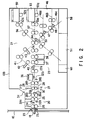
- the card processing mechanism 10b includes transfer means 22 for transferring cards 17 inserted through the opening 18 to card processing means 21 via gate means 20 and returning it to the opening 18.
- the gate means 20 is provided at a portion of a transfer path 22a, adjacent to the opening 18. It receives the cards 17 inserted through the opening 18 and transfers them to the card processing means 21 or discharges the cards 17 supplied from the card processing means 21 to the opening 18.
- the gate means 20 includes a fetch sensor 23 arranged in proximity to the opening 18 to detect insertion of a card.
- the gate means 20 also includes a lever 24 serving as restricting means, which is arranged on the transfer path 22a with a gap corresponding to the thickness of a piece of card.
- the lever 24 is rotatable in a direction indicated by an arrow s, although prevented from rotating in a direction indicated by an arrow t.
- First and second pinch roller pairs 25 and 26, rotatable forward and backward, are respectively arranged in front and rear of the lever 24.
- Upper rollers 25a and 26a of the first and second rollers 25 and 26 are normally pressed against lower rollers 25c and 26c by first and second springs 25b and 26b.
- the upper rollers 25a and 26a can be moved up by the springs 25b and 26b in accordance with the number of the cards 17 which pass through the transfer path 22a.
- first and second pinch rollers 25 and 26 are rotated in the forward direction, i.e., when cards 17 are taken into the machine through the opening 18, only the lower rollers 25c and 26c are driven, while the upper rollers 25a and 25b are maintained in a neutral state.
- the pinch rollers 25 and 26 are rotated in the backward direction, i.e., when cards are discharged through the opening 18, the upper and lower rollers 25a, 25c, 26a, and 26c are rotated so as to pinch the cards until they are discharged.
- An accumulating section 27 wherein the cards 17 are accumulated is formed between the second pinch rollers 26 and the card processing means 21.
- the accumulating section 27 includes first and second pulleys 28a and 28b and a pair of transfer belts 28 which are put on the pulleys 28a and 28b. It also includes a stopper 30 which is moved up and down by a driver means 30a so as to project in the transfer path 22a in order to temporarily stop the cards 17. It further includes a pair of third pinch rollers 31 rotatable forward and backward. An upper roller 31a of the third pinch rollers 31 is normally pressed against a lower roller 31c by a third spring 31b, but can be moved up by the spring 31b in accordance with the number of the cards 17 accumulated in the accumulating section 27. A sensor 32b counts the number of cards which are being accumulated.
- a sensor 32a detects the front and the rear ends of the cards 17. The detection result is input to an calculating section 70a of a control device 70 (to be described later), in which the length of the cards 17 is detected and the number of cards passed by is counted.
- the card processing means 21 includes, along the transfer path 22a, a punch device 36 for punching a hole in a card to indicate rough balance and first and second read/write magnetic heads 37 and 38 for reading data recorded on the cards 17 and writing an amount of money thereon.
- First and second thermal print heads 42 and 43 for printing balance on a prepaid card are arranged along a branch transfer path 41 branching from the transfer path 22a at a first branching gate 40.
- a second branching gate 44 guides the cards 17 to a card reservation section 46.
- Third and fourth gates 47 and 48 guide the cards 17 supplied through the transfer path 22a to one of first to third card reservation portions 46a to 46c. All rollers 49 in the transfer path 22a and the branch transfer path 41 extending from the punch device 36 to the third card reservation portion 46c are rotatable forward and backward.
- a fifth gate 50 guides a normal passenger-ticket (not shown) to a card collecting portion 51.
- First and second card hoppers 52 and 53 store unused cards 54 to be issued as new prepaid cards.
- First and second take-out rollers 52b and 53b take out cards 54 from bottom portions 52a and 53a of the first and second card hoppers 52 and 53, and supply them to first and second supply paths 56 and 57.
- a card collecting portion 58 collects invalid cards such as a season ticket which has passed the time limit, a prepaid card which has been used up, or a new prepaid card 54 on which incorrect data is written or printed. Punch chips produced in the punch device 36 are collected in a chip collecting portion 60.
- the cash processing mechanism 10a includes a sensor 62 for judging whether a coin or a banknote is counterfeit and a discriminator 63 for discriminating the type of a coin or banknote, which are arranged in coin and banknote transfer paths (not shown).
- the automatic fare adjustment machine 10 comprises a control device 70 which controls the entire operation of the machine and which has a calculating section (not shown).
- the calculating section calculates an amount to be adjusted on the basis of data read by the first and second read/write magnetic heads 37 and 38 from the normal passenger-ticket or the season ticket 17a. Subsequently, it calculates a balance on the prepaid card 17b or an adjusted amount from data on an amount of money inserted through the coin inserting port 14 or the banknote inserting port 16, judged by the sensor 62 of the cash processing mechanism 10a and discriminated by the discriminator 63.
- Fig. 3 is a block diagram showing the control system of the automatic fare adjustment machine 10.
- the control device 70 of the automatic fare adjustment machine 10 is connected through an input interface 71 to operation keys 12a, a fetch sensor 23, discriminating sensors 32a and 32b, and the sensor 62 and the discriminator 63 of the cash processing mechanism 10a.
- the control device 70 is also connected through an input/output interface 72 to first and second read/write magnetic heads 37 and 38 which are controlled by first and second magnetic controllers 73a and 73b and first and second amplifiers 73c and 73d.
- control device 70 is connected through an output interface 74 to a mechanical controller 76 and a mechanical driver 76a which is connected to the card transfer means 22 including the pinch rollers 25, 26, and 31, the pulleys 28a and 28b, the driver means 30a, and the branching gates.
- the mechanical driver 76a is also connected to cash transfer means 80 and the punch device 36.
- the control device 70 is further connected to first and second thermal print heads 42 and 43 which are controlled by first and second print controllers 77a and 77b and first and second print amplifiers 77c and 77d.
- the control device 70 is also connected to a display section 11 which is controlled by an operation controller 78 and an operation amplifier 78a.
- the season ticket 17a is pinched by the first lower roller 25c and the upper roller 25a, which is rotated in accordance with the rotation of the first lower roller 25c.
- the ticket 17a is transferred through the transfer path 22a to the lever 24.
- the lever 24 which is prevented from rotating in the direction indicated by the arrow t by means of a stopper pin 24a and arranged above the transfer path 22a with a gap corresponding to the thickness of a piece of card. Therefore, if a plurality of cards 17 are inserted, the lever 24 prevents a second or subsequent cards from being further transferred and only the lower-most card 17 is allowed to be transferred by the first lower roller 25c. Thus, only one card can pass under the lever at a time.
- the first upper roller 25a is moved up in accordance with the number of the inserted cards 17 as indicated by the dot line.
- the season ticket 17a separated by the lever 24 is pinched by the second pinch roller 26 and transferred by the transfer belt 28.
- the length of the ticket 17a is detected by the discriminating sensor 32 which detects the front and rear ends of the ticket, to judge whether the ticket is valid. If the discriminating sensor 32 judges the ticket not to be any one of a normal passenger-ticket, a season ticket 17a, and a prepaid card 17b, the ticket is immediately discharged through the opening 18, not transferred to the card processing means 21.
- the stopper 30 When the ticket 17a is inserted, the stopper 30 is located below the transfer path 22a. Hence, the ticket 17a is not stopped by the stopper 30 and transferred to the ticket processing means 21.
- the ticket 17a is transferred to the first read/write magnetic head 37 through the punch device 36.
- the recorded data such as the designated section, the available period, or the sex is read by the magnetic head 37 and the ticket 17a is reserved in the first card reservation portion 46a.
- the data read by the first read/write head 37 is input to the calculating section of the control device 70.
- An amount to be adjusted is calculated by the calculating section and displayed on the display section 11. If there is a plurality of routes to the station, instructions to input the route which the user has used are displayed on the display section 11. In this case, the amount to be adjusted is calculated after the user inputs the route through the operation keys 12a.
- the user When the amount to be adjusted is displayed on the display section 11, the user inserts one or two prepaid cards 17b through the opening 18.
- the inserted prepaid card 17b is transferred in the same manner as the season ticket 17a to the first read/write head 37 which reads the remainder on the card.
- the second read/write head 38 magnetically writes a balance after the fare adjustment. If the remainder on a first prepaid card is less than the amount to be paid, the first prepaid card is reserved in the second card reservation portion 46b.
- the first read/write head 37 reads the remainder on the second prepaid card and the second read/write head 38 writes a balance after the fare adjustment on the second prepaid card.
- the user inserts an amount of money corresponding to the shortage through the coin inserting port 14 or the banknote inserting port 16. In this case, if the amount of inserted money is greater than the shortage to be paid, the change is not given back to the user but a new prepaid card on which a balance corresponding to the change is recorded is issued.
- an unused prepaid card is taken out of the first or second card hoppers 52 and 53 by the first or second take-out rollers 52b and 53b, and the balance is magnetically written thereon by the second read/write head 38.
- the first and second prepaid cards 17b are reserved in the second and third card reservation portion 46b and 46c.
- the prepaid card 17b If necessary, after the prepaid card 17b is punched, it can be transferred to the blanch transfer path 41, in which the balance is printed on the rear surface of the card by means of the second thermal print head 43, before transferred to the accumulating section 27.
- the driver means 30a is driven so that the stopper 30 projects in the transfer path 22a. Hence, the new prepaid card 17b is brought into contact with the stopper 30 and stopped.
- the transfer rollers 49 in the first card reservation portion 46a are rotated backward to transfer the season ticket 17a to the second read/write head 38, which magnetically records completion of the fare adjustment on the season ticket 17a.
- the recorded data is checked by the first read/write head 37 and the season ticket 17a is transferred to the accumulating section 27.
- the season ticket 17a is transferred by the transfer belt 28 to a position on or under the new prepaid card 17b which has been stored in the accumulating section 27. Thus, the season ticket 17a and the prepaid card 17b are accumulated.
- the used-up prepaid cards 17b are taken out from the second and third card reservation portions 46b and 46c and transferred to the punch device 36.
- the punch device 36 forms a hole in each of the used-up card at a position indicating that the card is used up.
- the used-up prepaid cards are transferred to the accumulating section 27 and accumulated together with the new prepaid card 17b and the season ticket 17a.
- the upper roller 31a of the third pinch rollers 31 are sequentially moved up in accordance with the thickness (number) of the accumulated cards 17 against the spring 31b.
- the stopper 30 When all the cards 17 to be discharged to the user are accumulated in the accumulating section 27, the stopper 30 is moved down below the transfer path 22a. The accumulated cards 17 moves up the upper roller 26a, against the spring 26b, from the position indicated by the dot line to the position indicated by the solid line, as shown in Fig. 5. In the meantime, they are pinched by the second pinch rollers 26 and transferred to the lever 24. Since the lever 24 is freely rotated in the direction of the arrow s, the accumulated cards 17 are not stopped by the lever 24. The cards 17 moves up the upper roller 25a, against the spring 25b, from the position indicated by the dot line to the position indicated by the solid line, as shown in Fig. 5.
- the accumulated cards are pinched by the first pinch rollers 25.
- the cards are pinched by the first and second pinch rollers 25 and 26, they are kept accumulated and collectively discharged through the opening 18. In this manner, all the fare adjustment operation is completed.
- the user takes collectively all the cards 17 discharged through the opening 18, such as the season ticket 17a and the used-up and new prepaid cards 17b. Thereafter, he or she goes out of the station through an automatic ticket examination gate using the season ticket 17a on which the completion of the fare adjustment is recorded.
- an adjustment ticket is issued by a ticket issuing device (not shown) and discharged through the opening 18 together with a card-like ticket 17 used to adjust the fare.
- Fig. 6 is a diagram depicting a card accumulating operation of the gate mechanism according to the embodiment.
- the cards 17 are consecutively inserted aslant to the accumulating section 27 under the lower most card, without abutting against the edges of the already-accumulated cards, by means of pinch rollers 81 and 82 arranged between the accumulating section 27 and the transfer path 22a.
- pinch rollers 81 and 82 arranged between the accumulating section 27 and the transfer path 22a.
- the number of cards are counted by the sensor 32b and an appropriate number of cards are accumulated by an operation of the stopper 30. These operations are controlled by the control device 70 shown in Fig. 3.
- Fig. 7 is a flowchart showing an accumulating operation of the above embodiment.
- input cards are processed in a predetermined manner (S11).
- the stopper 30 is moved up so that the cards can be accumulated (S12).
- the control device 70 calculates the number of cards to be discharged (S13).
- the control device counts the number of cards to be accumulated (S14) by means of the sensor 32b and judges whether all the cards to be discharged are accumulated (S15). If all the cards are accumulated, the stopper 30 is moved down and the cards are discharged collectively (S16).
Landscapes
- Physics & Mathematics (AREA)
- General Physics & Mathematics (AREA)
- Devices For Checking Fares Or Tickets At Control Points (AREA)
- Ticket-Dispensing Machines (AREA)
- Control Of Vending Devices And Auxiliary Devices For Vending Devices (AREA)
Claims (8)
- Mediumverarbeitungsgerät zum Lesen einer ersten Information auf einem ersten Medium und einer zweiten, für einen Saldenpegel repräsentativen Information auf einem zweiten Medium, wobei das Gerät aufweist:eine erste Transporteinrichtung (22) zum Transportieren des ersten Mediums,eine erste Leseeinrichtung (37) zum Lesen der ersten Information auf dem ersten Medium, das durch die erste Transporteinrichtung (22) transportiert wird,eine Einrichtung (18) zum gleichzeitigen Aufnehmen des ersten Mediums und des zweiten Mediums.eine zweite Transporteinrichtung (22) zum Transportieren des zweiten Mediums, das durch die Aufnahmeeinrichtung (18) aufgenommen ist,eine zweite Leseeinrichtung (37) zum Lesen der zweiten Information auf dem zweiten Medium, das durch die zweite Transporteinrichtung (27) transportiert wird,eine Steuereinrichtung (70) zum Berechnen eines Wertpegels in Abhängigkeit von der ersten Information und zum Verringern des Saldenpegels in Abhängigkeit von dem Wertpegel, der durch die Steuereinrichtung (70) berechnet wird,eine Einrichtung (38) zum Aufzeichnen des verringerten, durch die Steuereinrichtung (70) reduzierten Saldenpegels auf dem zweiten Medium,eine Einrichtung (28) zum Sammeln des ersten Mediums und des zweiten Mediums, auf dem durch die Aufzeichnungseinrichtung (38) aufgezeichnet ist,eine Einrichtung (24) zum Regeln der ersten und der zweiten Transporteinrichtung zum separaten Transportieren des ersten Mediums und des zweiten Mediums zu der ersten und der zweiten Leseeinrichtung (37) und zum Ermöglichen eines Transports des ersten Mediums und des zweiten Mediums, die durch die Sammeleinrichtung (20) gesammelt wurden, durch die erste und die zweite Transporteinrichtung, undeine Einrichtung (18) zum gleichzeitigen Zurückführen des ersten Mediums und des zweiten Mediums. bezüglich derer dies durch die Regel- und Ermöglichungseinrichtung (24) ermöglicht ist.
- Mediumverarbeitungsgerät nach Anspruch 1, dadurch gekennzeichnet, daß die erste und die zweiten Transporteinrichtung (27) die Medien jeweils einzeln zu einem Zeitpunkt mit Hilfe eines Hebels (24) ergreifen.
- Mediumverarbeitungsgerät nach Anspruch 1 oder 2, dadurch gekennzeichnet, daß die Medien ein normales Passagierticket oder eine bereits vorausbezahlte Karte enthalten.
- Mediumverarbeitungsgerät nach Anspruch 1, 2 oder 3, dadurch gekennzeichnet, daß es weiterhin aufweist:eine Einrichtung (32b) zum Erfassen der Anzahl von gesammelten Medien,eine Einrichtung (70) zum Berechnen der Anzahl von Medien, die gleichzeitig abgegeben werden sollten, undeine Einrichtung (70) für die Beurteilung, ob die Medien, die abzugeben sind, gesammelt worden sind, so daß die Ausgabeeinrichtung die gesammelten Medien gleichzeitig ausgibt.
- Mediumverarbeitungsgerät nach einem der Ansprüche 1 bis 4, dadurch gekennzeichnet, daß die erste und die zweite Transporteinrichtung (27) einen Anschlag (30) enthalten.
- Mediumverarbeitungsgerät nach einem der Ansprüche 1 bis 5, dadurch gekennzeichnet, daß die Medien jeweils einzeln von der Seite zu der Sammeleinrichtung (20) unterhalb des untersten Mediums aus den Medien, die bereits gesammelt worden sind, eingeführt werden.
- Verfahren zum Ausgeben von Medien aus einem Mediumverarbeitungsgerät zum Lesen einer ersten Information auf einem ersten Medium und einer zweiten, einen Saldenpegel repräsentierenden Information auf einem zweiten Medium, wobei das Verfahren aufweist:ein erstes Transportieren (S11) des ersten Mediums,ein erstes Lesen (S11) der ersten Information auf dem ersten Medium, das bei dem ersten Transportschritt transportiert wird,gleichzeitiges Aufnehmen des ersten Mediums und des zweiten Mediums,ein zweites Transportieren (S11) des zweiten Mediums,ein zweites Lesen (S11) der zweiten Information auf dem zweiten Medium, das durch einen zweiten Transportschritt transportiert wird,Berechnen (S11) eines Wertepegels in Abhängigkeit von der ersten Information und Verringern des Saldenpegels in Abhängigkeit von dem Wertepegel, der durch eine Steuereinrichtung berechnet wird,Aufzeichnen (S11) des verringerten Saldenpegels, der durch die Steuereinrichtung verringert wurde, auf dem zweiten Medium,Sammeln (S12) einer Mehrzahl von Medien, die bei den Schritten gelesen oder berechnet oder mit Aufzeichnung versehen wurden,Berechnen (S13) der Anzahl von Medien, die gleichzeitig abgegeben werden sollten,Zählen (S14) der Anzahl der Medien, die bei dem Sammelschritt gesammelt wurden,Beurteilen (S15), ob die gesammelten Medien gleichzeitig abgegeben werden sollten, wobei hierzu die Anzahl, die bei dem Berechnungsschritt berechnet wurde, und die Anzahl, die bei dem Zählschritt (S14) gezählt wurde, verglichen werden, undAusgeben (S16) der gesammelten Medien (S16), wenn bei dem Beurteilungsschritt beurteilt wird, daß sie ausgegeben werden sollten.
- Verfahren nach Anspruch 7, dadurch gekennzeichnet, daß der Beurteilungsschritt (S15) durch einen Sensor zur Erfassung des Durchgangs eines Mediums und durch einen Mikrocomputer (70) ausgeführt wird, der ein Signal von dem Sensor wiederbelebt bzw. empfängt und die Anzahl der Medien zählt.
Applications Claiming Priority (2)
| Application Number | Priority Date | Filing Date | Title |
|---|---|---|---|
| JP192559/92 | 1992-07-21 | ||
| JP19255992A JP3197066B2 (ja) | 1992-07-21 | 1992-07-21 | 券類処理装置、自動精算装置 |
Publications (3)
| Publication Number | Publication Date |
|---|---|
| EP0580137A2 EP0580137A2 (de) | 1994-01-26 |
| EP0580137A3 EP0580137A3 (de) | 1994-11-17 |
| EP0580137B1 true EP0580137B1 (de) | 1997-01-02 |
Family
ID=16293297
Family Applications (1)
| Application Number | Title | Priority Date | Filing Date |
|---|---|---|---|
| EP19930111666 Expired - Lifetime EP0580137B1 (de) | 1992-07-21 | 1993-07-21 | Medium-Verarbeitungsvorrichtung zur kollektiven Ausgabe eines Vielzahl von Medien |
Country Status (4)
| Country | Link |
|---|---|
| EP (1) | EP0580137B1 (de) |
| JP (1) | JP3197066B2 (de) |
| DE (1) | DE69307039T2 (de) |
| HK (1) | HK1003019A1 (de) |
Families Citing this family (6)
| Publication number | Priority date | Publication date | Assignee | Title |
|---|---|---|---|---|
| DE29815185U1 (de) * | 1998-08-25 | 1998-12-03 | Weig, Gabriele, 60596 Frankfurt | Mehretagiges Parkhaus sowie Gerät zur Identifikation einer Parketage |
| FR2812743B1 (fr) * | 2000-08-02 | 2003-01-24 | Dassault Automatismes | Dispositif d'interface utilisateur/machine destine a etre associe a un dispositif de traitement pour controler l'introduction de titres plats, souples et comportant une piste magnetique |
| FR2812742A1 (fr) * | 2000-08-02 | 2002-02-08 | Dassault Automatismes | Dispositif d'interface utilisateur/machine destine a etre associe a un dispositif de traitement de titres, notamment de titres plats et souples comportant une piste magnetique, afin de delivrer ergonomiquement un ou plusieurs titres a... |
| JP4635823B2 (ja) * | 2005-10-26 | 2011-02-23 | シンフォニアテクノロジー株式会社 | 媒体の重ね合わせ装置 |
| EP3051501B1 (de) * | 2011-07-29 | 2018-12-05 | Nidec Sankyo Corporation | Verarbeitungsvorrichtung für ein medium und steuerverfahren für die verarbeitungsvorrichtung für ein medium |
| CN110473299A (zh) * | 2019-08-16 | 2019-11-19 | 苏州富欣智能交通控制有限公司 | 一种用于有轨电客的客票检测方法 |
Family Cites Families (4)
| Publication number | Priority date | Publication date | Assignee | Title |
|---|---|---|---|---|
| JPS5935285A (ja) * | 1982-08-24 | 1984-02-25 | 株式会社東芝 | 証書類発行装置 |
| DE3881268T2 (de) * | 1987-04-23 | 1994-01-13 | Oki Electric Ind Co Ltd | Fahrkartenverarbeitungsendgerät. |
| DE68909279T2 (de) * | 1988-03-30 | 1994-05-05 | Sanyo Denki Seisakusho Gifu Kk | Fahrgeldabgleichmaschine für eine im voraus bezahlte Fahrkarte. |
| US5120947A (en) * | 1990-03-29 | 1992-06-09 | International Totalizator Systems, Inc. | Apparatus and method for processing a ticket |
-
1992
- 1992-07-21 JP JP19255992A patent/JP3197066B2/ja not_active Expired - Lifetime
-
1993
- 1993-07-21 EP EP19930111666 patent/EP0580137B1/de not_active Expired - Lifetime
- 1993-07-21 DE DE69307039T patent/DE69307039T2/de not_active Expired - Fee Related
-
1998
- 1998-03-12 HK HK98102044A patent/HK1003019A1/xx not_active IP Right Cessation
Also Published As
| Publication number | Publication date |
|---|---|
| DE69307039T2 (de) | 1997-08-07 |
| HK1003019A1 (en) | 1998-09-30 |
| EP0580137A3 (de) | 1994-11-17 |
| EP0580137A2 (de) | 1994-01-26 |
| DE69307039D1 (de) | 1997-02-13 |
| JPH0636092A (ja) | 1994-02-10 |
| JP3197066B2 (ja) | 2001-08-13 |
Similar Documents
| Publication | Publication Date | Title |
|---|---|---|
| EP0580137B1 (de) | Medium-Verarbeitungsvorrichtung zur kollektiven Ausgabe eines Vielzahl von Medien | |
| JP2746833B2 (ja) | カード処理装置 | |
| JP2687221B2 (ja) | 自動改札装置 | |
| JP2825240B2 (ja) | 改札システム | |
| JP2746940B2 (ja) | 自動改札装置 | |
| JP2003108948A (ja) | カード処理装置 | |
| JPH0773345A (ja) | 券類処理装置 | |
| JP3884822B2 (ja) | 自動精算機 | |
| JP3107788B2 (ja) | カード処理装置 | |
| JP3335209B2 (ja) | カード印字装置 | |
| JP2885567B2 (ja) | 自動精算機 | |
| JP3435332B2 (ja) | 情報記録媒体処理装置 | |
| JP2001076191A (ja) | カード処理装置 | |
| JPH07200887A (ja) | 券類処理装置 | |
| JPS63148393A (ja) | 鑑別装置 | |
| JPH01180063A (ja) | 携帯可能媒体の処理システム | |
| JPH09185732A (ja) | 乗車券等を扱う自動改札機及び自動精算機 | |
| JPH0793601A (ja) | 券売機 | |
| JPH02148289A (ja) | 自動券売機及び金額カード処理機 | |
| JPH076855U (ja) | 自動精算機 | |
| JPH11191166A (ja) | カード処理方法およびカード処理装置 | |
| JP2000215332A (ja) | カ―ド処理方法およびカ―ド処理装置 | |
| JP2000251102A (ja) | カード処理装置 | |
| JPH0773348A (ja) | 券類処理装置 | |
| JPH09180014A (ja) | 自動改札装置 |
Legal Events
| Date | Code | Title | Description |
|---|---|---|---|
| PUAI | Public reference made under article 153(3) epc to a published international application that has entered the european phase |
Free format text: ORIGINAL CODE: 0009012 |
|
| 17P | Request for examination filed |
Effective date: 19930721 |
|
| AK | Designated contracting states |
Kind code of ref document: A2 Designated state(s): DE FR GB |
|
| RIN1 | Information on inventor provided before grant (corrected) |
Inventor name: NAGASHIMA, MASAYOSHI, C/O INTELLECT. PROPERTY DIV Inventor name: HOMMA, MAMORU, C/O INTELLECTUAL PROPERTY DIV. |
|
| PUAL | Search report despatched |
Free format text: ORIGINAL CODE: 0009013 |
|
| AK | Designated contracting states |
Kind code of ref document: A3 Designated state(s): DE FR GB |
|
| 17Q | First examination report despatched |
Effective date: 19950724 |
|
| GRAG | Despatch of communication of intention to grant |
Free format text: ORIGINAL CODE: EPIDOS AGRA |
|
| GRAG | Despatch of communication of intention to grant |
Free format text: ORIGINAL CODE: EPIDOS AGRA |
|
| GRAH | Despatch of communication of intention to grant a patent |
Free format text: ORIGINAL CODE: EPIDOS IGRA |
|
| GRAH | Despatch of communication of intention to grant a patent |
Free format text: ORIGINAL CODE: EPIDOS IGRA |
|
| GRAA | (expected) grant |
Free format text: ORIGINAL CODE: 0009210 |
|
| AK | Designated contracting states |
Kind code of ref document: B1 Designated state(s): DE FR GB |
|
| REF | Corresponds to: |
Ref document number: 69307039 Country of ref document: DE Date of ref document: 19970213 |
|
| ET | Fr: translation filed | ||
| PGFP | Annual fee paid to national office [announced via postgrant information from national office to epo] |
Ref country code: DE Payment date: 19970725 Year of fee payment: 5 |
|
| PLBE | No opposition filed within time limit |
Free format text: ORIGINAL CODE: 0009261 |
|
| STAA | Information on the status of an ep patent application or granted ep patent |
Free format text: STATUS: NO OPPOSITION FILED WITHIN TIME LIMIT |
|
| 26N | No opposition filed | ||
| PG25 | Lapsed in a contracting state [announced via postgrant information from national office to epo] |
Ref country code: DE Free format text: LAPSE BECAUSE OF NON-PAYMENT OF DUE FEES Effective date: 19990501 |
|
| REG | Reference to a national code |
Ref country code: GB Ref legal event code: IF02 |
|
| PGFP | Annual fee paid to national office [announced via postgrant information from national office to epo] |
Ref country code: FR Payment date: 20040708 Year of fee payment: 12 |
|
| PGFP | Annual fee paid to national office [announced via postgrant information from national office to epo] |
Ref country code: GB Payment date: 20040721 Year of fee payment: 12 |
|
| PG25 | Lapsed in a contracting state [announced via postgrant information from national office to epo] |
Ref country code: GB Free format text: LAPSE BECAUSE OF NON-PAYMENT OF DUE FEES Effective date: 20050721 |
|
| GBPC | Gb: european patent ceased through non-payment of renewal fee |
Effective date: 20050721 |
|
| PG25 | Lapsed in a contracting state [announced via postgrant information from national office to epo] |
Ref country code: FR Free format text: LAPSE BECAUSE OF NON-PAYMENT OF DUE FEES Effective date: 20060331 |
|
| REG | Reference to a national code |
Ref country code: FR Ref legal event code: ST Effective date: 20060331 |