EP0566163B1 - Hebelitze - Google Patents
Hebelitze Download PDFInfo
- Publication number
- EP0566163B1 EP0566163B1 EP93109182A EP93109182A EP0566163B1 EP 0566163 B1 EP0566163 B1 EP 0566163B1 EP 93109182 A EP93109182 A EP 93109182A EP 93109182 A EP93109182 A EP 93109182A EP 0566163 B1 EP0566163 B1 EP 0566163B1
- Authority
- EP
- European Patent Office
- Prior art keywords
- heald
- lifting
- guide slot
- limb
- leg
- Prior art date
- Legal status (The legal status is an assumption and is not a legal conclusion. Google has not performed a legal analysis and makes no representation as to the accuracy of the status listed.)
- Expired - Lifetime
Links
- 210000003414 extremity Anatomy 0.000 claims 9
- 210000003141 lower extremity Anatomy 0.000 claims 1
- 239000000428 dust Substances 0.000 description 4
- 238000003466 welding Methods 0.000 description 3
- 238000004026 adhesive bonding Methods 0.000 description 1
- 230000015572 biosynthetic process Effects 0.000 description 1
- 238000004519 manufacturing process Methods 0.000 description 1
- 239000002184 metal Substances 0.000 description 1
- 238000000034 method Methods 0.000 description 1
Images


Classifications
-
- D—TEXTILES; PAPER
- D03—WEAVING
- D03C—SHEDDING MECHANISMS; PATTERN CARDS OR CHAINS; PUNCHING OF CARDS; DESIGNING PATTERNS
- D03C7/00—Leno or similar shedding mechanisms
- D03C7/02—Gauze healds
-
- D—TEXTILES; PAPER
- D03—WEAVING
- D03C—SHEDDING MECHANISMS; PATTERN CARDS OR CHAINS; PUNCHING OF CARDS; DESIGNING PATTERNS
- D03C9/00—Healds; Heald frames
- D03C9/02—Healds
Definitions
- the subject matter of the application is a lifting heald, consisting of two legs of different widths, each end having a fastening element for receiving a heald frame, with means for magnetically controlling a lifting leg provided with two legs being arranged on the wide leg, the wide leg of the lifting heald being one Has stop for the half strand.
- a lifting wire is known for example from utility model DE-U 88 07 217.7.
- a disadvantage of this lifting heald is that the metallic web of the half heald abuts against the inner web of the lifting heald during the reciprocal movement of the heald frames, and cuts the lifting heald there permanently.
- the lifting heald is incised, there is a risk of binding errors occurring, because ultimately there is no longer any guarantee that the leno thread will surely pass from one side of the half heald to the other when changing the shed.
- leg of the half strand strikes the stop with its lower free end. This ensures that before the web of the semi-strands on the inner web of the lifting strands strikes, the leg of the half-strand hits the stop with its free end.
- the distance of the stop from the inner web of the lifting health corresponds approximately to the leg length of the half heald.
- the stop itself is preferably made of plastic and should be arranged interchangeably in the leg of the lifting heald.
- the wide leg of the lifting heald has a guide slot for the half heald; the stop itself is arranged in the guide slot.
- one leg of the lifting heald with a guide slot causes the half-heald to be guided precisely. This is of particular interest if magnets are provided in the wide leg of the lifting heald for magnetic control of the metallic half strands.
- the guide slot ensures that the half heald, even at high speed of the heald frames, is always gripped by the magnets.
- the width of the end of the guide slot provided in this leg is adapted to the width of the upper leg of the lifting heald, so that the end of the guide slot is exposed.
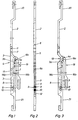
- the lifting heald denoted overall by 1, consists of the upper leg 2 and the lower leg 3.
- the lower leg 3 of the lifting heald is wider than the upper leg 2; both legs each have fastening elements 20, 21 on their ends for receiving the heald frames (not shown).
- connection of the legs 2 and 3 is carried out with the aid of a connecting lug, designated overall by 4, which according to the exemplary embodiment is a U-rail piece.
- the web of the U-rail section is designated 5.
- this web of the U-rail section is tapered at 6 or 6a.
- the cheeks 5a of the U-rail piece are tapered at 11 in order to offer only little resistance to the leno thread running along.
- connection strap is connected to the legs 2 and 3, e.g. with the help of rivets 7.
- the wider leg 3 of the lifting heald has the guide slot 8 for the half heald 19.
- the upper end of the guide slot 8 is delimited by the web 3a, on which the web 19a of the half heald 19 rests during the entraining movement by the lifting heald.
- the pin which is made of plastic, is detachably arranged in the leg 3, so that the possibility of exchanging this pin arises when worn.
- the legs 2 and 3 of the lifting heald 1 are made of plastic; on the other hand, there is the connecting tab, i.e. the U-rail piece 4 made of metal to make this part more wear-resistant; because in this area the leno threads run along.
- Fig. 3 shows another embodiment of the lifting heald.
- the connecting tab 4a is adapted in the middle part at 13 to the width of the upper leg 2, whereby the dust removal, in particular of the dust pushed out of the guide slot 8, is facilitated, since the end 13 of the guide slot 8 is exposed due to this design of the connecting tab.
- the connecting link 4b is provided with openings 14, 15, the opening 14 in the cheek 16 and the opening 15 in the web 17 of the U-rail piece, so that dust removal is also ensured in this embodiment.
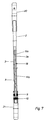
- FIGS. 6 and 7 show a lifting heald in which the fastening elements 20, 21 arranged on the end of the lifting heald are attached to receive the heald frames.
- the fastening elements 20, 21 are each provided with a slot 20a or 21a, into which the legs 2 or 3 protrude.
- connection of the fastening elements 20, 21, which are made of plastic, with the respective leg 2 or 3 is carried out by gluing or welding, e.g. by welding with the help of the ultrasonic welding process.
- the width of the lower leg 3 in the region of the end of the guide slot provided in this leg 3 is adapted to the width of the upper leg 2 of the half-heald 1, so that the end 18 of the guide slot 8 is exposed.
Landscapes
- Textile Engineering (AREA)
- Engineering & Computer Science (AREA)
- Auxiliary Weaving Apparatuses, Weavers' Tools, And Shuttles (AREA)
- Insulated Conductors (AREA)
- Conveying And Assembling Of Building Elements In Situ (AREA)
- Coating With Molten Metal (AREA)
- Ropes Or Cables (AREA)
- Communication Cables (AREA)
- Sewing Machines And Sewing (AREA)
- Reciprocating, Oscillating Or Vibrating Motors (AREA)
- Audible-Bandwidth Dynamoelectric Transducers Other Than Pickups (AREA)
- Sanitary Thin Papers (AREA)
- Food-Manufacturing Devices (AREA)
- Endoscopes (AREA)
- Investigating Materials By The Use Of Optical Means Adapted For Particular Applications (AREA)
- Looms (AREA)
Applications Claiming Priority (3)
| Application Number | Priority Date | Filing Date | Title |
|---|---|---|---|
| DE3912733 | 1989-04-19 | ||
| DE3912733A DE3912733C1 (enExample) | 1989-04-19 | 1989-04-19 | |
| EP90106757A EP0393460B1 (de) | 1989-04-19 | 1990-04-09 | Hebelitze |
Related Parent Applications (2)
| Application Number | Title | Priority Date | Filing Date |
|---|---|---|---|
| EP90106757.9 Division | 1990-04-09 | ||
| EP90106757A Division EP0393460B1 (de) | 1989-04-19 | 1990-04-09 | Hebelitze |
Publications (2)
| Publication Number | Publication Date |
|---|---|
| EP0566163A1 EP0566163A1 (de) | 1993-10-20 |
| EP0566163B1 true EP0566163B1 (de) | 1996-05-29 |
Family
ID=6378925
Family Applications (2)
| Application Number | Title | Priority Date | Filing Date |
|---|---|---|---|
| EP93109182A Expired - Lifetime EP0566163B1 (de) | 1989-04-19 | 1990-04-09 | Hebelitze |
| EP90106757A Expired - Lifetime EP0393460B1 (de) | 1989-04-19 | 1990-04-09 | Hebelitze |
Family Applications After (1)
| Application Number | Title | Priority Date | Filing Date |
|---|---|---|---|
| EP90106757A Expired - Lifetime EP0393460B1 (de) | 1989-04-19 | 1990-04-09 | Hebelitze |
Country Status (7)
| Country | Link |
|---|---|
| US (1) | US5040571A (enExample) |
| EP (2) | EP0566163B1 (enExample) |
| JP (1) | JP2549570B2 (enExample) |
| AT (1) | ATE106464T1 (enExample) |
| DE (2) | DE3912733C1 (enExample) |
| DK (1) | DK0393460T3 (enExample) |
| ES (1) | ES2055208T3 (enExample) |
Cited By (1)
| Publication number | Priority date | Publication date | Assignee | Title |
|---|---|---|---|---|
| DE202018107373U1 (de) | 2018-12-21 | 2019-01-29 | Gebrüder Klöcker GmbH | Vorrichtung zum Bilden einer Dreherkante |
Families Citing this family (18)
| Publication number | Priority date | Publication date | Assignee | Title |
|---|---|---|---|---|
| US6076250A (en) * | 1996-01-13 | 2000-06-20 | Firma Schmeing Gmbh & Co. | Process for producing a heald shaft for weaving shafts out of a metal hollow section |
| DE29703896U1 (de) | 1997-03-04 | 1998-07-02 | Klöcker-Entwicklungs-GmbH, 46325 Borken | Hebelitze |
| DE19750804C1 (de) * | 1997-11-17 | 1999-05-12 | Kloecker Entwicklungs Gmbh | Halblitze einer Dreherkantenvorrichtung mit Hebelitzen |
| BE1012258A3 (nl) * | 1998-10-30 | 2000-08-01 | Picanol Nv | Broekhevelinrichting voor een weefmachine. |
| DE19915815C1 (de) * | 1999-04-08 | 2000-09-28 | Schmeing Gmbh & Co | Hebelitze zur Bildung einer Dreherkante |
| WO2000061845A2 (de) * | 1999-04-10 | 2000-10-19 | Schmeing Gmbh & Co. | Vorrichtung zum bilden einer dreherkante |
| DE10035886A1 (de) * | 2000-07-24 | 2002-02-14 | Schmeing Gmbh & Co | Weblitze |
| DE10257519B3 (de) * | 2002-12-10 | 2004-04-01 | Klöcker-Entwicklungs-Gmbh | Vorrichtung zum Bilden einer Dreherkante |
| US7131465B1 (en) * | 2004-06-24 | 2006-11-07 | Chapman Arthur S | Removable plastic heddle with mating insertion tool for weaving apparatus |
| DE102004030913B3 (de) * | 2004-06-25 | 2005-07-07 | Klöcker-Entwicklungs-Gmbh | Litze, insbesondere Hebelitze |
| DE102005006477B3 (de) * | 2005-02-12 | 2006-01-05 | Klöcker-Entwicklungs-Gmbh | Litze, insbesondere Hebelitze |
| GB2432595B (en) * | 2005-11-24 | 2010-09-29 | John Rush | Direct warp selection device |
| BE1017202A3 (nl) * | 2006-07-03 | 2008-04-01 | Picanol Nv | Een sleetvaste inrichting voor het vormen van een leno binding. |
| PT2063007E (pt) * | 2007-11-21 | 2010-12-22 | Groz Beckert Kg | Dispositivo para fabrico de gazes |
| JP5188944B2 (ja) * | 2008-12-08 | 2013-04-24 | 株式会社豊田自動織機 | 綜絖枠 |
| US8944116B2 (en) * | 2013-03-07 | 2015-02-03 | Rome Division Rummel Fibre Co., Inc. | Leno heddle |
| CN116200873B (zh) * | 2023-03-31 | 2025-08-22 | 福清信首塑料制品有限公司 | 智能化织机的补综 |
| DE102024115051B3 (de) * | 2024-05-29 | 2025-06-18 | Gebrüder Klöcker GmbH | Dreherkantenvorrichtung zur bildung einer dreherkante |
Family Cites Families (7)
| Publication number | Priority date | Publication date | Assignee | Title |
|---|---|---|---|---|
| US2665489A (en) * | 1949-10-22 | 1954-01-12 | Helen M Cunningham | Adjusting device |
| CH352480A (de) * | 1957-01-24 | 1961-02-28 | Schneider & Co Ag | Aufhängevorrichtung für verschiedene Gegenstände, wie z.B. Decken, Beleuchtungskörper, Leitungen usw. |
| CH535304A (de) * | 1972-06-19 | 1973-03-31 | Egelhaaf C C Fa | Nadelstab-Dreherwebeeinrichtung |
| CH579161A5 (enExample) * | 1974-06-10 | 1976-08-31 | Grob & Co Ag | |
| AT332318B (de) * | 1974-06-17 | 1976-09-27 | Grob & Co Ag | Dreher-webelitze |
| DE3818680C5 (de) * | 1988-06-01 | 2006-06-22 | Klöcker-Entwicklungs-Gmbh | Vorrichtung zum Bilden einer Dreherkante |
| DE8807217U1 (de) * | 1988-06-03 | 1988-12-29 | Klöcker, Heinz Josef, 4280 Borken | Vorrichtung zum Bilden einer Dreherkante, wobei wechselseitig bewegte Webschäfte vorgesehen sind |
-
1989
- 1989-04-19 DE DE3912733A patent/DE3912733C1/de not_active Expired - Fee Related
-
1990
- 1990-04-09 EP EP93109182A patent/EP0566163B1/de not_active Expired - Lifetime
- 1990-04-09 ES ES90106757T patent/ES2055208T3/es not_active Expired - Lifetime
- 1990-04-09 DE DE59005876T patent/DE59005876D1/de not_active Expired - Lifetime
- 1990-04-09 AT AT90106757T patent/ATE106464T1/de not_active IP Right Cessation
- 1990-04-09 DK DK90106757.9T patent/DK0393460T3/da active
- 1990-04-09 EP EP90106757A patent/EP0393460B1/de not_active Expired - Lifetime
- 1990-04-17 US US07/510,606 patent/US5040571A/en not_active Expired - Lifetime
- 1990-04-18 JP JP2100575A patent/JP2549570B2/ja not_active Expired - Fee Related
Cited By (3)
| Publication number | Priority date | Publication date | Assignee | Title |
|---|---|---|---|---|
| DE202018107373U1 (de) | 2018-12-21 | 2019-01-29 | Gebrüder Klöcker GmbH | Vorrichtung zum Bilden einer Dreherkante |
| EP3670721A1 (de) | 2018-12-21 | 2020-06-24 | Gebrüder Klöcker GmbH | Vorrichtung zum bilden einer dreherkante |
| US11047071B2 (en) | 2018-12-21 | 2021-06-29 | Gebrüder Klöcker GmbH | Apparatus for forming a leno selvage |
Also Published As
| Publication number | Publication date |
|---|---|
| EP0393460A2 (de) | 1990-10-24 |
| DE59005876D1 (de) | 1994-07-07 |
| EP0566163A1 (de) | 1993-10-20 |
| JPH02293432A (ja) | 1990-12-04 |
| EP0393460A3 (de) | 1991-04-17 |
| JP2549570B2 (ja) | 1996-10-30 |
| US5040571A (en) | 1991-08-20 |
| ATE106464T1 (de) | 1994-06-15 |
| DK0393460T3 (da) | 1994-06-20 |
| ES2055208T3 (es) | 1994-08-16 |
| DE3912733C1 (enExample) | 1990-07-26 |
| EP0393460B1 (de) | 1994-06-01 |
Similar Documents
| Publication | Publication Date | Title |
|---|---|---|
| EP0566163B1 (de) | Hebelitze | |
| DE2726023A1 (de) | Skibremsvorrichtung | |
| EP2520384A1 (de) | Windewerkzeug für Federwindemaschinen | |
| DE29612662U1 (de) | Korkenzieher | |
| DE29710184U1 (de) | Einstellbare Fahrradbremse | |
| DE2606081B2 (de) | Litzentragschiene mit verbinder und/oder endstueck | |
| EP1743966B1 (de) | Weblitze, insbesondere für schnell laufende Webmaschinen | |
| EP4332285A1 (de) | Führungsvorrichtung für eine ringspinnmaschine, ringspinnmaschine sowie verwendung einer führungsvorrichtung | |
| EP1130143B1 (de) | Fachbildeeinrichtung für Webmaschinen | |
| DE3830107A1 (de) | Drehervorrichtung fuer webmaschinen | |
| DE202013102865U1 (de) | Griff | |
| DE4323673C2 (de) | Schmuckstückverschluß | |
| EP2019157B1 (de) | Schmale gekröpfte Weblitze | |
| CH634359A5 (de) | Verbindungsstab zwischen dem schaftrahmen einer webmaschine und dem schaftzughebel der sie steuernden fachbildemaschine. | |
| DE8033674U1 (de) | Vorrichtung zum blockieren eines verschiebbaren organs in bezug auf eine stange einer bueromaschine | |
| DE3440518C2 (enExample) | ||
| EP0154110B1 (de) | Klappstecker und Verfahren zu seiner Herstellung | |
| DE4024638C2 (enExample) | ||
| DE849677C (de) | Webschaft | |
| DE3028033C2 (de) | Relais mit einer mechanischen Schaltstellungsanzeige | |
| DE3236035C1 (de) | Vorrichtung zur Herstellung einer Gewebe-Schnittleiste | |
| EP0759376B1 (de) | Führungsschieneneinrichtung für einen Fahrzeugsitz | |
| DE571288C (de) | Aufzugsachse mit neben ihrer Wurzel offener Griffoese fuer Spielzeug-Bandfedertriebwerke | |
| DE8905644U1 (de) | Federbügelzirkel | |
| DE8811682U1 (de) | Vorrichtung zum Fördern von Gegenständen |
Legal Events
| Date | Code | Title | Description |
|---|---|---|---|
| PUAI | Public reference made under article 153(3) epc to a published international application that has entered the european phase |
Free format text: ORIGINAL CODE: 0009012 |
|
| AC | Divisional application: reference to earlier application |
Ref document number: 393460 Country of ref document: EP |
|
| AK | Designated contracting states |
Kind code of ref document: A1 Designated state(s): BE CH IT LI |
|
| 17P | Request for examination filed |
Effective date: 19931110 |
|
| 17Q | First examination report despatched |
Effective date: 19941216 |
|
| GRAH | Despatch of communication of intention to grant a patent |
Free format text: ORIGINAL CODE: EPIDOS IGRA |
|
| GRAA | (expected) grant |
Free format text: ORIGINAL CODE: 0009210 |
|
| AC | Divisional application: reference to earlier application |
Ref document number: 393460 Country of ref document: EP |
|
| AK | Designated contracting states |
Kind code of ref document: B1 Designated state(s): BE CH IT LI |
|
| REG | Reference to a national code |
Ref country code: CH Ref legal event code: NV Representative=s name: R. A. EGLI & CO. PATENTANWAELTE |
|
| ITF | It: translation for a ep patent filed | ||
| PLBE | No opposition filed within time limit |
Free format text: ORIGINAL CODE: 0009261 |
|
| STAA | Information on the status of an ep patent application or granted ep patent |
Free format text: STATUS: NO OPPOSITION FILED WITHIN TIME LIMIT |
|
| 26N | No opposition filed | ||
| PGFP | Annual fee paid to national office [announced via postgrant information from national office to epo] |
Ref country code: CH Payment date: 20040402 Year of fee payment: 15 |
|
| PGFP | Annual fee paid to national office [announced via postgrant information from national office to epo] |
Ref country code: BE Payment date: 20040527 Year of fee payment: 15 |
|
| PG25 | Lapsed in a contracting state [announced via postgrant information from national office to epo] |
Ref country code: IT Free format text: LAPSE BECAUSE OF NON-PAYMENT OF DUE FEES;WARNING: LAPSES OF ITALIAN PATENTS WITH EFFECTIVE DATE BEFORE 2007 MAY HAVE OCCURRED AT ANY TIME BEFORE 2007. THE CORRECT EFFECTIVE DATE MAY BE DIFFERENT FROM THE ONE RECORDED. Effective date: 20050409 |
|
| PG25 | Lapsed in a contracting state [announced via postgrant information from national office to epo] |
Ref country code: LI Free format text: LAPSE BECAUSE OF NON-PAYMENT OF DUE FEES Effective date: 20050430 Ref country code: CH Free format text: LAPSE BECAUSE OF NON-PAYMENT OF DUE FEES Effective date: 20050430 Ref country code: BE Free format text: LAPSE BECAUSE OF NON-PAYMENT OF DUE FEES Effective date: 20050430 |
|
| BERE | Be: lapsed |
Owner name: *KLOCKER-ENTWICKLUNGS-G.M.B.H. Effective date: 20050430 |
|
| REG | Reference to a national code |
Ref country code: CH Ref legal event code: PL |
|
| BERE | Be: lapsed |
Owner name: *KLOCKER-ENTWICKLUNGS-G.M.B.H. Effective date: 20050430 |