EP0565970A1 - Blutlanzettenvorrichtung zur Entnahme von Blut für Diagnosezwecke - Google Patents
Blutlanzettenvorrichtung zur Entnahme von Blut für Diagnosezwecke Download PDFInfo
- Publication number
- EP0565970A1 EP0565970A1 EP93105481A EP93105481A EP0565970A1 EP 0565970 A1 EP0565970 A1 EP 0565970A1 EP 93105481 A EP93105481 A EP 93105481A EP 93105481 A EP93105481 A EP 93105481A EP 0565970 A1 EP0565970 A1 EP 0565970A1
- Authority
- EP
- European Patent Office
- Prior art keywords
- lancet
- blood
- holder
- housing
- rotary slide
- Prior art date
- Legal status (The legal status is an assumption and is not a legal conclusion. Google has not performed a legal analysis and makes no representation as to the accuracy of the status listed.)
- Granted
Links
Images


Classifications
-
- A—HUMAN NECESSITIES
- A61—MEDICAL OR VETERINARY SCIENCE; HYGIENE
- A61B—DIAGNOSIS; SURGERY; IDENTIFICATION
- A61B5/00—Measuring for diagnostic purposes; Identification of persons
- A61B5/15—Devices for taking samples of blood
- A61B5/151—Devices specially adapted for taking samples of capillary blood, e.g. by lancets, needles or blades
- A61B5/15186—Devices loaded with a single lancet, i.e. a single lancet with or without a casing is loaded into a reusable drive device and then discarded after use; drive devices reloadable for multiple use
- A61B5/15188—Constructional features of reusable driving devices
- A61B5/15192—Constructional features of reusable driving devices comprising driving means, e.g. a spring, for retracting the lancet unit into the driving device housing
- A61B5/15194—Constructional features of reusable driving devices comprising driving means, e.g. a spring, for retracting the lancet unit into the driving device housing fully automatically retracted, i.e. the retraction does not require a deliberate action by the user, e.g. by terminating the contact with the patient's skin
-
- A—HUMAN NECESSITIES
- A61—MEDICAL OR VETERINARY SCIENCE; HYGIENE
- A61B—DIAGNOSIS; SURGERY; IDENTIFICATION
- A61B5/00—Measuring for diagnostic purposes; Identification of persons
- A61B5/15—Devices for taking samples of blood
- A61B5/150007—Details
- A61B5/150015—Source of blood
- A61B5/150022—Source of blood for capillary blood or interstitial fluid
-
- A—HUMAN NECESSITIES
- A61—MEDICAL OR VETERINARY SCIENCE; HYGIENE
- A61B—DIAGNOSIS; SURGERY; IDENTIFICATION
- A61B5/00—Measuring for diagnostic purposes; Identification of persons
- A61B5/15—Devices for taking samples of blood
- A61B5/150007—Details
- A61B5/150175—Adjustment of penetration depth
- A61B5/150183—Depth adjustment mechanism using end caps mounted at the distal end of the sampling device, i.e. the end-caps are adjustably positioned relative to the piercing device housing for example by rotating or screwing
-
- A—HUMAN NECESSITIES
- A61—MEDICAL OR VETERINARY SCIENCE; HYGIENE
- A61B—DIAGNOSIS; SURGERY; IDENTIFICATION
- A61B5/00—Measuring for diagnostic purposes; Identification of persons
- A61B5/15—Devices for taking samples of blood
- A61B5/150007—Details
- A61B5/150374—Details of piercing elements or protective means for preventing accidental injuries by such piercing elements
- A61B5/150381—Design of piercing elements
- A61B5/150412—Pointed piercing elements, e.g. needles, lancets for piercing the skin
-
- A—HUMAN NECESSITIES
- A61—MEDICAL OR VETERINARY SCIENCE; HYGIENE
- A61B—DIAGNOSIS; SURGERY; IDENTIFICATION
- A61B5/00—Measuring for diagnostic purposes; Identification of persons
- A61B5/15—Devices for taking samples of blood
- A61B5/151—Devices specially adapted for taking samples of capillary blood, e.g. by lancets, needles or blades
- A61B5/15101—Details
- A61B5/15103—Piercing procedure
- A61B5/15107—Piercing being assisted by a triggering mechanism
- A61B5/15113—Manually triggered, i.e. the triggering requires a deliberate action by the user such as pressing a drive button
-
- A—HUMAN NECESSITIES
- A61—MEDICAL OR VETERINARY SCIENCE; HYGIENE
- A61B—DIAGNOSIS; SURGERY; IDENTIFICATION
- A61B5/00—Measuring for diagnostic purposes; Identification of persons
- A61B5/15—Devices for taking samples of blood
- A61B5/151—Devices specially adapted for taking samples of capillary blood, e.g. by lancets, needles or blades
- A61B5/15101—Details
- A61B5/15115—Driving means for propelling the piercing element to pierce the skin, e.g. comprising mechanisms based on shape memory alloys, magnetism, solenoids, piezoelectric effect, biased elements, resilient elements, vacuum or compressed fluids
- A61B5/15117—Driving means for propelling the piercing element to pierce the skin, e.g. comprising mechanisms based on shape memory alloys, magnetism, solenoids, piezoelectric effect, biased elements, resilient elements, vacuum or compressed fluids comprising biased elements, resilient elements or a spring, e.g. a helical spring, leaf spring, or elastic strap
-
- A—HUMAN NECESSITIES
- A61—MEDICAL OR VETERINARY SCIENCE; HYGIENE
- A61B—DIAGNOSIS; SURGERY; IDENTIFICATION
- A61B5/00—Measuring for diagnostic purposes; Identification of persons
- A61B5/15—Devices for taking samples of blood
- A61B5/151—Devices specially adapted for taking samples of capillary blood, e.g. by lancets, needles or blades
- A61B5/15101—Details
- A61B5/15126—Means for controlling the lancing movement, e.g. 2D- or 3D-shaped elements, tooth-shaped elements or sliding guides
- A61B5/1513—Means for controlling the lancing movement, e.g. 2D- or 3D-shaped elements, tooth-shaped elements or sliding guides comprising linear sliding guides
Definitions
- the invention relates to a blood lancet device for withdrawing blood for diagnostic purposes, which has a housing with an outlet opening for the tip of a lancet, a lancet holder movable in the housing along a predetermined straight puncture path for holding the lancet and a lancet guide for guiding the lancet holder on the predetermined straight line Insertion path.
- the lancet holder is moved during the puncturing and return movement by a lancet drive which has an elastic drive element, usually a metal spring. It can be locked in a first position, in which the elastic drive element is in a tensioned state, by means of a locking device.
- the elastic drive element relaxes and its movement is converted into the puncturing movement by the lancet drive, the lancet held by the lancet holder at high speed along the predetermined insertion path is moved in the insertion direction until its tip emerges from the outlet opening in order to create a wound in a part of the body pressed against the outlet opening (fingers or earlobes). Immediately afterwards, the lancet is returned by the lancet drive.
- lancets are used in medical practice, which are pierced into the corresponding part of the body by the doctor or laboratory personnel, either manually or with simple equipment.
- the lancet must of course be sharp and sterile.
- the blood samples are taken from individual patients at large intervals and the puncture is carried out by trained, specially trained personnel.
- the object of the invention is therefore to provide a blood lancet device which, with a simple construction, produces the puncture in a manner which leads to a reduced sensation of pain.
- the lancet drive has a rotary slide gear which has a gear member which can be rotated about an axis of rotation parallel to the predetermined puncture path and by which a torque is introduced on the input side of the rotary slide gear is converted into a longitudinal displacement in the direction of the predetermined puncture path, the rotatable gear member of the rotary slide mechanism is coupled to the elastic drive element and the output-side longitudinal displacement of the rotary slide mechanism is transmitted to the lancet holder.
- the term "gearbox” is understood in the general sense, i.e. as a kinematic device which is used for coupling and converting movements, in the present case the movement when the elastic drive element relaxes (which is also referred to below as a drive spring without restriction of generality) into the movement of the lancet holder or one therein, preferably interchangeable, attached lancet is converted.
- the transmission of the rotary movement of the input-side transmission member into a translation movement parallel to its axis of rotation is preferably carried out with the aid of a cam control, at least part of the puncturing and preferably also the return movement being determined by a relative movement of a control pin in a recess forming the control curve, in which the Journals a control curve formed by the recess.
- the recess which forms the control cam can be provided either in the component forming the rotatable gear member or in an adjacent displaceable component be. Accordingly, the pin is rigidly connected to an adjacent displaceable component or to the component forming the rotatable gear member.
- a preferred embodiment is one in which the rotatable gear member of the rotary sliding gear has a cylindrical sleeve, within which a piston-shaped part is arranged, which slides with a cylindrical outer wall in the sleeve during longitudinal displacement in the direction of the insertion path, in this case the sleeve being rotatable, however not axially displaceable and the axially displaceable piston-shaped part arranged therein should be non-rotatable.
- the piston-shaped part is preferably a component of the lancet holder or is firmly connected to it.
- the blood lancet device according to the invention is characterized above all by the fact that the vibrations during the puncturing and return movement are very slight, because apart from the lancet holder itself, no other components are accelerated and braked in the puncturing direction. In the context of the invention it was found that this low level of vibration contributes significantly to a painless puncture.
- the invention allows a simple and low-play construction of the drive with few components and good guidance of the lancet holder. As a result, vibrations during the puncturing and return movement are largely avoided at low manufacturing costs. This is also - as was determined in the context of the invention - an essential contribution to reducing the sensation of pain.
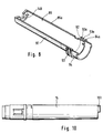
- the invention allows a handy and compact design, the housing preferably having an elongated shape (so-called "pencil shape”) and its longitudinal axis running parallel to the puncturing direction. This enables convenient storage and easier handling.
- the lancet drive and the lancet holder in the lancet holder are designed such that the puncture depth by which the tip of the lancet during the puncture movement emerges from the outlet opening, with the setting of the blood lancet device unchanged and successive puncturing movements varied by no more than at most 0.15 mm, preferably at most 0.1 mm, particularly preferably at most 0.05 mm.
- the insertion depth should be easily and precisely adjustable by the user.
- the setting range preferably includes unusually low penetration depths between 0.5 and 2.0 mm, the range between 0.7 mm and 1.3 mm being of particular importance.
- the amount of blood required in practice for the analysis which is usually between 1 and 50 .mu.l, in the majority of cases between 10 and 30 .mu.l, surprisingly already with such low in the vast majority of people Penetration depths with significantly reduced pain can be obtained if at the same time it is ensured that the depth of the puncture is extraordinarily reproducible with a certain, unchanged setting of the device.
- the adjustment mechanism for the adjustment of the penetration depth is preferably designed such that it can be adjusted in steps, the step spacing being at most approximately at least in the above-mentioned preferred adjustment range (0.5 to 2.0 mm, preferably 0.7 to 1.3 mm) 0.4 mm and at least about 0.2 mm, preferably about 0.3 mm.
- the entire setting range can go beyond the sub-ranges mentioned and also include greater puncture depths, in order to meet the requirements of the relatively few people for whom the aforementioned low puncture depths (for example because of a particularly thick cornea) cannot be used to obtain a sufficient amount of blood.
- the reproducibility of the penetration depth depends on two factors. First, it is important that the movement of the lancet holder is controlled so precisely that the lowest point of its movement is reproducible in the direction of the puncture. Secondly, it is important that the lancet is positioned so precisely in its holder that the position of the tip in the direction of the puncturing movement relative to the lancet holder is reproducible if several lancets are fastened in succession in the lancet holder. Both conditions can be easily achieved with known mechanical means, provided that relatively high-quality materials are used in the production and that production is carried out with small tolerances.
- the lancet drive explained in connection with the first main aspect of the invention is particularly preferred because it achieves the desired reproducibility with relatively little production effort.
- a significant improvement in the positioning of the lancet in the lancet holder and consequently in the reproducibility of the puncture depth is achieved by a preferred embodiment in which the metallic needle of the lancet has a positioning element and the lancet holder has a stop for the positioning element and the lancet is held in the lancet holder in this way that the positioning element is pressed elastically against the stop.
- the lancets always have a metallic needle, one end of which is sharpened to a point.
- the rear part of the lancet needle facing away from the tip is usually enclosed by a plastic lancet body (US Pat. No. 3,358,689).
- the production is usually carried out in such a way that the lancet needle is positioned in a plastic injection mold and the lancet body is molded on.
- Such lancets are fixed in the lancet holder with the aid of the lancet body.
- the depth of the puncture movement is usually limited by the fact that the front edge of the lancet body strikes against a stop rigidly connected to the housing of the lancet devices in the area of the blood lancet outlet opening.
- the penetration depth influenced by several tolerances. Above all, it was found in the context of the present invention that the manufacturing tolerance of the position of the needle tip in relation to the position of the plastic body is an essential factor which impairs the reproducibility.
- the variation in the penetration depth from lancet to lancet is only influenced by the tolerance of the distance between the positioning element and the tip of the metallic needle.
- the positioning element can be formed by the rear end of the needle or by a projection projecting laterally from the needle. It is easily possible to maintain very narrow tolerances of the distance between the positioning element and the tip of the lancet using conventional means of metal processing.
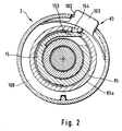
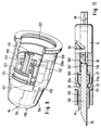
- a lancet drive 3 Arranged within the housing 1 of the blood lancet device 2 shown in FIG. 1 is a lancet drive 3, which has a rotary sliding gear 4 with a rotatable gear member 5 on the input side and a lancet holder 6 which can be displaced in the direction of the axis of rotation A of the gear member 5.
- the torque introduced on the input side 16 of the rotary slide transmission 4 is generated by an elastic drive element 9 of the lancet drive 3.
- the elastic drive element 9 is a helical spiral spring 10. This is supported on a spring stop 11 of the housing 1 with one end 12 from and with the second end 13 in an axial slot 14 at the input-side (right in the figure) end of the gear member 5, which is designed as a cylindrical sleeve 15.
- the helical spiral spring 10 is arranged coaxially to the axis of rotation A of the rotary slide transmission 4.
- the lancet holder 6 is located within the sleeve 15.
- a piston-shaped part 20, the outer diameter of which is slightly smaller than the inner diameter of the sleeve 15, is part of the lancet holder 6 and can slide with its cylindrical outer wall 20b along the inner wall of the sleeve 15.
- the inner wall of the sleeve 15 thus forms a lancet guide 15b during the puncturing and return movement.
- the sleeve 15 is fixed against axial displacement in the housing 1 and can only perform a rotary movement about the axis of rotation A.
- the lancet holder 6 is formed approximately as a hollow cylinder with an approximately constant inner diameter (Fig. 5 and Fig. 7).
- the lancet holder 6 is provided with two cutouts on its jacket wall 26, into which two symmetrical tongues 27 arranged approximately axially parallel project. These are each connected on one side to the piston-shaped part 20.
- a nose 29 is formed, the spacing of which from one another in the relaxed state of the tongues 27 is less than the inside diameter of the lancet holder 6. If there is a lancet 34 (shown in FIG.
- the jacket 38 of the piston-shaped part 20 is provided with a groove-shaped recess 39 with a rectangular cross section, which forms a control curve 40 for the rotary slide transmission 4.
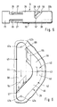
- the development of the contours of the recess 39 in one plane is shown in FIG. 6. It can be seen that the recess 39 has two partial curves 41, 42 with a constant groove width.
- the first sub-curve 41 is formed along a circumferential line of the jacket 38 of the cylindrical part 20, in the preferred case shown the angular distance between the start 41 a and the end 41 b of the first sub-curve 41 is approximately 140 °.
- the recess 39 merges into the second sub-curve 42, which connects the beginning 41a and the end 41b of the first sub-curve 41 with the same groove width.
- the second sub-curve 42 runs in an arc shape. Like the first partial curve 41, it is arranged symmetrically with respect to the axis 44.
- the second sub-curve 42 has a line segment 45 which continuously merges into a curve segment 46 which, after an apex 43, runs symmetrically to the axis 44 to the end 42b.
- the end 42b of the second sub-curve 42 corresponds to the start 41a of the first sub-curve.
- Both sub-curves 41, 42 form the control curve 40, which is closed in a ring.
- the cylindrical sleeve 15 (FIG. 1) there is an approximately axially parallel elastic tongue 51 fastened on one side, at the free end of which a cylindrical control pin 52 pointing into the interior of the sleeve 15 is attached, which engages in the recess 39 of the piston-shaped part 20 and the control curve 40 formed by the recess 39 by a relative movement with the piston-shaped part can move off.
- the groove width of the recess 39 is matched to the diameter of the cylinder of the control pin 52 so that the control pin 52 is at least on the largest part of the control curve 40 in positive engagement with the recess 39.
- a ramp-like step 54, 55 is provided in front of the end 41b, 42b of the two subcurves 41, 42 in the recess 39 (FIG. 6), which extends from the bottom of the groove 56 starts to rise uniformly and then ends with a flank 57, 68 that falls perpendicularly to the groove base 56.
- the control pin 52 comes to rest at the end of each partial curve 41, 42 in such a way that it can only move in the direction of the end 41b, 42b of the respective other partial curve 41, 42.
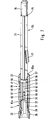
- a cylindrical part 60 of a plunger 59 (FIG. 7).
- the longitudinal axis of the plunger 59 coincides with the longitudinal axis of the lancet holder 6 and the axis of rotation A of the sleeve 15.
- the cylindrical part 60 of the plunger 59 has a diametric slot 62 almost along its entire longitudinal axis, through which the cylindrical part 60 of the plunger forms a fork 61.
- the distance between the two plane-parallel surfaces 63, 64 of the fork 61 is matched to the thickness of the web 36 so that the cylindrical part 60 of the plunger 59 can be moved axially in the piston-shaped part 20 of the lancet holder 6, the plane-parallel surfaces 63, 64 on the slide both surfaces 65, 66 of the web 36.
- the plunger 59 merges into a profile rod 71 with a cross-shaped cross section, which are arranged such that it can also slide in the cylindrical recess 58 of the piston-shaped part 20.
- At the end of the plunger 59 there is an actuating pin 76 with an approximately square cross section.
- a tongue 77 is attached, which limits the axial displacement of the plunger 59 in the lancet holder 6 when it abuts against a web 70 of the cylindrical sleeve 15.
- the plunger 59 is located in the blood lancet device 2 such that the actuating pin 76 protrudes from a corresponding opening 78 in the housing 1, as a result of which the plunger 59 is mounted in a rotationally fixed manner relative to the housing 1 (FIG. 1).
- a shoulder 79 formed at the transition from the profile rod 71 to the actuating button serves as a stop on the housing 1 when the plunger 59 is axially displaced.
- the profile rod 71 is inserted through the helical spiral spring 10.
- the spiral spring 10 is in an untensioned state (FIGS. 1 and 6).
- the control pin 52 is moved in the control curve 40 of the piston-shaped part 20 to the end 41b of the first partial curve 41, and the spiral spring 10 coupled to the sleeve 15 is brought into a tensioned state.
- step 54 there is a short non-rising surface section 54a, which is somewhat lower than the upper edge of the side walls of the recess 39.
- the bending tension of the tongue 51 causes that the control pin 52 is pressed onto the groove base 56 at the end of the first sub-stage 41b.
- the vertical flank 57 of step 54 prevents the sleeve 15 with the control pin 52 from being able to move back along the first partial curve 41 due to the now tensioned state of the spiral spring 10.
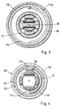
- a locking device 83 locks the cylindrical sleeve 15 in this position of the control pin 52 (Fig.1 and Fig.2). If the locking device 83 is released, the spring tension of the spiral spring 10 causes a torque to be transmitted to the input side 16 of the rotary slide transmission 4, the sleeve 15 being turned back against the previous direction of rotation and the control pin 52 driving the second sub-curve 42 (FIG. 1 and Fig. 6).
- the piston-shaped part 20 which is fixed against rotational movements, is longitudinally displaced in the housing 1 in the direction of its outlet opening 84 until the control pin 52 has reached the apex 43 of the second sub-curve 42 and the tip 35 of the lancet 34 through the outlet opening 84 exit. If the control pin 52 is located at the apex 43 of the second sub-curve 42, the tip 35 of the lancet 34 has reached its greatest longitudinal displacement in the direction of the puncture path.
- the puncture depth corresponds to the distance between the tip 35 and the pressure surface 82 (in the direction of the puncture path).
- the return movement of the lancet 34 is ended when the control pin has reached the end 42b of the second sub-curve 42, which is identical to the start 41a the first sub-curve 41. Just before it gets there, it glides over the second ramp-like step 55, which also has a non-rising surface section 55a and a vertical flank 68 at its end.
- the level 55 ramp is long and flat to slow down the movement. As a result, the control pin 52 can only continue to move along the first sub-curve 41.
- the puncture and return movement of the lancet 34 is achieved by converting the rotary movement about the axis of rotation A of the helically wound spiral spring 10 and the gear member 5 into a longitudinal displacement of the lancet holder 6 in the direction of the predetermined puncture path and then in the opposite direction.
- the positive locking of the recess 39 and the control pin 52 is only provided on partial sections, in particular the section between the beginning 41a and the apex 43 of the second partial curve 42.
- the housing 1 of the blood lancet device 2 is composed of several elements.
- the cylindrical sleeve 15 is located in a housing cylinder 85 that is open on one side.
- the end face of the cylindrical sleeve 15 protrudes from the open end 90 of the housing cylinder 85.
- On the outer surface 91 of the housing cylinder 85 three circumferential webs 92, 93, 94 are attached in the region of the open end 90 (FIG. 8), the first 92 and the second web 93 with their outer edges 92a, 93a being at a greater distance from the outer surface 91 have the outer edge 94a of the third web 94.
- a cover ring is supported on the outer edges 92a, 93a of these two webs 92,93 100, which has an opening 102 for receiving a button 103 for releasing the locking device 83 (FIG. 2).
- the cover ring 100 is open on the first end face, which faces the lancet tip 35, while the second end face is provided with a circular recess, the diameter of which corresponds approximately to the diameter of the lateral surface 91 of the housing cylinder 85.
- the cover ring 100 has an anti-rotation device and a bead 107 which runs in the circumferential direction on the inner circumferential surface and is located between the first web 92 and second web 93 of the housing cylinder 85 (FIG. 1).
- An intermediate ring 110 adjoins the open end of the cover ring 100, which is supported on the second web 93 of the housing cylinder 85 and on the third web 94 of the housing cylinder 85 with a bead 113 running in the circumferential direction (FIG. 1).
- the intermediate ring 110 encompasses an enlarged collar 114 of a clamping sleeve 115.
- the clamping sleeve 115 is pushed axially approximately in the position of the lancet receiving part 22 onto the cylindrical sleeve 15 and fixed with it against displacement in the direction of the longitudinal axis.
- a cutout 116 is provided in the jacket of the cylindrical sleeve 15 along approximately half a circumferential line, into which a driver 117 of the clamping sleeve 115 engages (FIG. 4).
- an external thread 121 is attached to the end of the clamping sleeve 115 facing the outlet opening 84, while the locking ring 120 is provided with a corresponding internal thread 122 (FIGS. 1 and 9).
- a second internal thread 123 is a closure cap 124 with an external thread 125 in the end of the outlet opening 84 facing Locking ring 120 screwed in.
- the closure cap 124 is closed on the first end face 126 apart from the puncture opening 84, the outer surface 126 a of the end face 126 being placed on a skin site when the blood lancet device 2 is used.
- the thread 123, 125, with which the closure cap 124 and the closure ring 120 are connected, is used to adjust the penetration depth.
- the lancet drive 3 and the possibility of adjustment by the thread 123, 125 are coordinated together with the dimensions of the lancets 34 to be used so that the penetration depth can be adjusted in a desired setting range, which in a preferred embodiment includes setting depths between 0.7 mm and 2.2 mm , where successive puncturing movements vary with the setting of the blood lancet device 2 unchanged with respect to the puncturing depth by at most 0.15 mm, preferably at most 0.1 mm, particularly preferably at most 0.05 mm.
- a latching device 130 is provided, as shown in FIG. 9.
- the locking ring 120 is provided on its inner circumferential surface 120a in a radially circumferential manner with evenly distributed raised knobs 131. Between each of these knobs 131 there is a latching tongue 132, which is fastened to the closure cap 124 on one side and parallel to the longitudinal axis on the jacket 127 of the closure cap 124, to lie in the free area between two knobs 131 with almost no play.
- the elastically designed latching tongue 132 slides over a knob 131 and comes to lie in the next free area between two knobs 131.
- a marking 133 is attached to the closure ring 120, with the aid of which the set penetration depth can be recognized on a scale 134 on the closure cap 124.
- the clamping sleeve 115 is rotated with the cylindrical sleeve 15, which are in engagement with the driver 117 and the first end face 138 of the cutout 116 (FIGS. 1 and 4) .
- the blood lancet device 2 is thereby tensioned.
- the control pin 52 stands at the start 41a of the first sub-curve 41 and travels it to the end 41b, the step 55 forcibly specifying the direction of movement.
- the lancet holder 6 remains in its position in the housing 1 without executing any movement. This has the advantage that the lancet tip 35 does not emerge through the outlet opening 84 during the clockwise rotation and thus an unwanted risk of injury during the tensioning process is excluded.
- the helical spiral spring 10 and an elastic return element which in the preferred embodiment shown is also in the form of a helical spiral spring 140, is placed in a tensioned state.
- the return spring 140 is supported on the one hand on the housing cylinder 85 and on the other hand on the clamping sleeve 115 (FIG. 1).
- the clockwise rotation is ended by the abutment of a stop web 149 of the housing cylinder 85 and a stop lug 151 of the cylindrical sleeve 15 (FIGS. 8 and 10).
- the control pin 52 comes to lie at the end 41b of the first sub-curve 41 behind the vertical flank 57 of the step 54 and an elastic locking tongue 153 (FIG. 2) of the locking device 83 snaps into a corresponding locking recess 154 located on the jacket 85a of the housing cylinder 85 and locks the blood lancet device 2 in the tensioned state.
- the tensioning device 137 thus has an actuating element 155 accessible from the outside of the housing 1 (in the preferred case shown, the locking ring 120), which is coupled to the input side 16 of the rotary slide transmission 4 in such a way that the elastic drive element 9 of the lancet drive 3 by rotation of the actuating element 155 is brought into the tensioned state relative to the housing 1 (FIG. 1).
- the lancing process is initiated.
- the elastic locking pin 153 fastened to the drive sleeve 15 is moved from the locking recess 154 of the housing cylinder 85 into the interior of the housing cylinder 85, as a result of which the drive sleeve 15 for rotary movements is released relative to the housing 1 (Fig.2).
- the storage of the key 103 is designed such that it is held in the depressed position when the blood lancet device 2 is not tensioned. Only when the spiral spring 10 is tensioned is the button 103 pressed outwards. The operating state of the blood lancet device 2 can thus be recognized from the position of the button 103.
- the key 103 is enclosed by the cover ring 100 and also held by the cover ring in relation to the housing 1.
- the spring tension of the spiral spring 10 now initiates a left turn of the drive sleeve 15. As described, the control pin 52 travels the second partial curve 42 of the control curve 40 during this left rotation.
- the blood lancet device 2 has a low accelerated mass in the direction of the longitudinal movement of the lancet 34, the puncture is largely vibration-free. This is an important prerequisite for a painless puncture, as has been shown in studies within the scope of the invention.
- the described guidance of the lancet holder 6 within the rotary slide mechanism is a further contribution to the vibration-free and thus pain-free puncture.
- the locking ring 120 with the locking cap 124 is unscrewed by turning it to the left.
- the plunger 59 is moved in the direction of the outlet opening of the housing along the axis of rotation A (FIG. 1 and FIG. 7).
- the end face 61a of the fork 61 presses on the lancet 34, which is thereby ejected.
- the axial movement of the plunger 59 is limited by the tongue 77 of the plunger, which on the web 70 of the cylindrical Sleeve 15 hits.
- the new lancet 34 is inserted into the lancet receiving part 22 of the lancet holder 6 and pushed in up to the first end face 37 of the web 36.
- the plunger 59 is pressed back and the lancet 34 clamped by the two lugs.
- the lancet 34 shown in FIG. 11 consists, as usual, of a plastic body 165 and a metallic needle 166. However, it is of a novel design in that the rear end 167 of the metallic needle 166 protrudes beyond the rear end 168 of the plastic body 165. The rear end face of the rear end 167 serves as a positioning element 169. It bears against a stop 170 of the lancet holder 7, which in the case shown is formed by the web 36.
- the lancet 34 is held in the lancet holder 6 in such a way that the lancet 34 with the positioning element 169 is pressed backwards against the stop 170 (counter to the puncturing direction).
- This is achieved in the illustrated embodiment in that the V-shaped recesses 171, into which the lugs 29 of the elastic tongues 27 engage, are designed and arranged such that the rear oblique surface 29a abuts a corresponding oblique surface 171a of the recesses 171 and a force component against the puncturing direction results from the pressure of the tongues 27 directed in the direction of the axis A.
- the body 165 of the lancet 134 is preferably not round, but is, for example, square. Appropriate shaping of the interior of the lancet receiving part 22 ensures that it is secured against rotation.
- FIGS. 12 and 13 differs primarily in that the needle 176 is not round in cross section, but consists of a thin flat material.
- the shape of the needle can be seen in FIG. 12 in a side view of the narrow edge and in FIG. 13 in a side view of the surface.
- FIG. 12 shows a tip protection 177a which can be removed by turning and which, as is also the case with other lancets, is molded onto the needle 176 together with the plastic body 177 and is removed before the lancet is used.
- the needle 176 is contained in a plastic body 177, which in this case also has V-shaped recesses 171 which cooperate with the lugs 29 of the elastic tongues 27 of the holder 6 in the same way as in FIG. 11 in order to produce a resulting force component that acts on the lancet against the direction of the puncture.
- the positioning element 169 is a pin-shaped projection 178 which projects laterally from the needle 176 and which bears against a lower end face 179 of the receiving part 22 of the lancet holder 6 forming the stop 170.
- Such a lancet can be easily produced in a stamping process. It is characterized by particularly close tolerances of the distance between the lancet tip 35 and the positioning element 169 and thus by particularly good reproducibility of the penetration depth.
- the flat shape enables the lancet tip to be designed relatively broadly in the plane of the needle 176. As a result, a relatively high amount of blood is drawn with little pain and a small puncture depth.
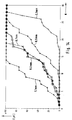
- FIG. 14 graphically shows results that were achieved on thirty test subjects with the blood lancet device according to the invention.
- the number N of the test persons is plotted on the abscissa and the amount of blood obtained in ⁇ l is plotted on the ordinate.
- the five curves shown show the results at penetration depths of 0.3 mm, 0.5 mm, 0.7 mm, 0.9 mm and 1.1 mm penetration depth. It can be seen that in the vast majority of the test subjects, insufficient amounts of blood were obtained at a penetration depth of 0.3 mm. In twenty-one subjects, the blood volume was less than 10 ⁇ l.
- Fig. 14 shows that at the penetration depths 0.7 mm and 0.9 mm blood quantities of 20 ⁇ l and more were already obtained from 2/3 of the test persons. In modern analysis devices, this amount is often sufficient for an exact analysis.
Landscapes
- Health & Medical Sciences (AREA)
- Life Sciences & Earth Sciences (AREA)
- Molecular Biology (AREA)
- Surgery (AREA)
- Biophysics (AREA)
- Pathology (AREA)
- Engineering & Computer Science (AREA)
- Biomedical Technology (AREA)
- Heart & Thoracic Surgery (AREA)
- Medical Informatics (AREA)
- Hematology (AREA)
- Physics & Mathematics (AREA)
- Animal Behavior & Ethology (AREA)
- General Health & Medical Sciences (AREA)
- Public Health (AREA)
- Veterinary Medicine (AREA)
- Dermatology (AREA)
- Measurement Of The Respiration, Hearing Ability, Form, And Blood Characteristics Of Living Organisms (AREA)
- Measuring Pulse, Heart Rate, Blood Pressure Or Blood Flow (AREA)
- Investigating Or Analysing Biological Materials (AREA)
- Apparatus For Radiation Diagnosis (AREA)
Abstract
Description
- Die Erfindung betrifft eine Blutlanzettenvorrichtung zur Entnahme von Blut für Diagnosezwecke, welche ein Gehäuse mit einer Austrittsöffnung für die Spitze einer Lanzette, einen in dem Gehäuse entlang einem vorbestimmten geraden Einstichweg beweglichen Lanzettenhalter zur Halterung der Lanzette und eine Lanzettenführung zur Führung des Lanzettenhalters auf dem vorbestimmten geraden Einstichweg aufweist. Der Lanzettenhalter wird bei der Einstich- und Rückführbewegung von einem Lanzettenantrieb bewegt, der ein elastisches Antriebselement, üblicherweise eine Metallfeder aufweist. Er ist in einer ersten Position, in der sich das elastische Antriebselement in einem gespannten Zustand befindet, mittels einer Arretiervorrichtung arretierbar. Nach dem Lösen der Arretiervorrichtung entspannt sich das elastische Antriebselement und seine Bewegung wird durch den Lanzettenantrieb in die Einstichbewegung umgesetzt, wobei die von dem Lanzettenhalter gehaltene Lanzette mit hoher Geschwindigkeit entlang dem vorbestimmten Einstichweg in Einstichrichtung bewegt wird, bis ihre Spitze aus der Austrittsöffnung austritt, um in einem gegen die Austrittsöffnung gedrückten Körperteil (Finger oder Ohrläppchen) eine Wunde zu erzeugen. Unmittelbar danach wird die Lanzette durch den Lanzettenantrieb wieder zurückgeführt.
- Um für Diagnosezwecke eine geringe Menge Blut aus dem Finger oder dem Ohrläppchen zu entnehmen, werden in der ärztlichen Praxis Lanzetten verwendet, die manuell oder mit einer einfachen Apparatur von dem Arzt oder Laborpersonal in das entsprechende Körperteil gestochen werden. Die Lanzette muß selbstverständlich scharf und steril sein. Im übrigen sind aber in der ärztlichen Praxis keine besonders hohen Anforderungen zu stellen, weil die Blutentnahmen bei einzelnen Patienten in großen zeitlichen Abständen durchgeführt werden und der Einstich durch trainiertes, speziell ausgebildetes Personal ausgeführt wird.
- Wesentlich höher sind dagegen die Anforderungen bei Blutlanzettenvorrichtungen, die zur Handhabung durch den Patienten selbst bestimmt sind. Sie werden vor allem benötigt, um im Rahmen des sogenannten "home monitoring" besonders gefährdeten Patientengruppen eine regelmäßige Überwachung bestimmter analytischer Werte ihres Blutes zu ermöglichen.
- Dies gilt insbesondere für Diabetiker, die ihren Blutzuckerspiegel häufig und regelmäßig kontrollieren sollten, um durch Anpassung der Insulininjektionen an den Bedarf, der von der Nahrungsaufnahme, der körperlichen Aktivität und anderen Faktoren abhängt, möglichst ständig innerhalb bestimmter Sollgrenzen zu halten. Dies ist für die Gesundheit solcher Patienten und die Vermeidung schwerwiegender Spätschäden, wie beispielsweise Erblindung und Amputation von Körperteilen, von allergrößter Bedeutung.
- Aus diesem Grunde wurden kleine, einfach zu bedienende und verhältnismäßig kostengünstige Analysesysteme entwickelt, die meist aus Blutteststreifen und einem zugehörigen Auswertegerät bestehen. Obwohl deswegen heute die Möglichkeit zur Analyse jedem Patienten problemlos und relativ kostengünstig zur Verfügung gestellt werden kann, hat die Selbstkontrolle der Blutzuckerwerte noch nicht die wünschenswerte allgemeine Verbreitung unter Diabetikern gefunden. Ein Hauptgrund dafür sind die Schmerzen, die mit der Erzeugung der für die Blutentnahme erforderlichen Stichwunde verbunden sind.
- Es wurden zahlreiche verschiedene Blutlanzettenvorrichtungen entwickelt, die geeignet sein sollen, die für die Blutgewinnung erforderliche Stichwunde auf einfache Weise und verhältnismäßig schmerzarm zu erzeugen. Beispiele sind in den US-Patentschriften 4 442 836, 4 469 110, 4 535 769 und 4 924 897 beschrieben. Blutentnahmegerät und Lanzette sind meist aufeinander abgestimmt und werden auch als Blutentnahmesystem bezeichnet. Trotz einiger Fortschritte ist auch bei diesen bekannten, insbesondere für die Benutzung durch den Patienten selbst bestimmten Blutlanzettenvorrichtung der durch den Einstich erzeugte Schmerz noch zu groß.
- Der Erfindung liegt daher die Aufgabe zugrunde, eine Blutlanzettenvorrichtung zur Verfügung zu stellen, die bei einfacher Bauweise den Einstich in einer Art und Weise erzeugt, die zu einem verminderten Schmerzempfinden führt.
- Die Aufgabe wird bei einer Blutlanzettenvorrichtung der eingangs bezeichneten Art gemäß einem ersten Hauptaspekt der Erfindung dadurch gelöst, daß der Lanzettenantrieb ein Drehschiebegetriebe aufweist, welches ein um eine zu dem vorbestimmten Einstichweg parallele Drehachse drehbares Getriebeglied aufweist und durch welches ein auf der Eingangsseite des Drehschiebegetriebes eingeleitetes Drehmoment in eine Längsverschiebung in Richtung des vorbestimmten Einstichweges umgewandelt wird, das drehbare Getriebeglied des Drehschiebegetriebes mit dem elastischen Antriebselement gekoppelt ist und die ausgangsseitige Längsverschiebung des Drehschiebegetriebes auf den Lanzettenhalter übertragen wird.
- Der Begriff "Getriebe" wird dabei im allgemeinen Sinn verstanden, d.h. als eine kinematische Vorrichtung, die zur Kopplung und Umwandlung von Bewegungen dient, wobei im vorliegenden Falle die Bewegung bei der Entspannung des elastischen Antriebselementes (welches nachfolgend ohne Beschränkung der Allgemeinheit auch als Antriebsfeder bezeichnet wird) in die Bewegung des Lanzettenhalters bzw. einer darin, vorzugsweise auswechselbar, befestigten Lanzette umgewandelt wird.
- Vorzugsweise erfolgt die Übertragung der Drehbewegung des eingangsseitigen Getriebegliedes in eine zu seiner Drehachse parallele Translationsbewegung mit Hilfe einer Kurvensteuerung, wobei mindestens ein Teil der Einstich- und bevorzugt auch der Rückführbewegung durch eine Relativbewegung eines Steuerzapfens in einer die Steuerkurve bildenden Ausnehmung bestimmt wird, bei der der Zapfen eine durch die Ausnehmung gebildete Steuerkurve abfährt. Die Ausnehmung, die die Steuerkurve bildet, kann entweder in dem das drehbare Getriebeglied bildenden Bauteil oder in einem benachbarten verschiebbaren Bauteil vorgesehen sein. Entsprechend ist der Zapfen starr mit einem benachbarten verschiebbaren Bauteil bzw. mit dem das drehbare Getriebeglied bildenden Bauteil verbunden.
- Bevorzugt ist eine Ausbildung, bei der das drehbare Getriebeglied des Drehschiebegetriebes eine zylindrische Hülse aufweist, innerhalb der ein kolbenförmiges Teil angeordnet ist, das bei Längsverschiebung in Richtung des Einstichweges mit einer zylindrischen Außenwand in der Hülse gleitet, wobei in diesem Falle die Hülse drehbar, jedoch in axialer Richtung nicht verschiebbar und das darin angeordnete axial verschiebbare kolbenförmige Teil drehfest sein sollte. In diesem Falle ist das kolbenförmige Teil vorzugsweise ein Bestandteil des Lanzettenhalters oder mit diesem fest verbunden.
- Die erfindungsgemäße Blutlanzettenvorrichtung zeichnet sich vor allem dadurch aus, daß die Erschütterungen bei der Einstich- und Rückführbewegung sehr gering sind, weil außer dem Lanzettenhalter selbst keine weiteren Bauteile in der Einstichrichtung beschleunigt und abgebremst werden. Im Rahmen der Erfindung wurde gefunden, daß diese Erschütterungsarmut wesentlich zu einem schmerzarmen Einstich beiträgt.
- Weiterhin erlaubt die Erfindung eine einfache und spielarme Konstruktion des Antriebs mit wenigen Bauteilen und guter Führung des Lanzettenhalters. Dadurch werden bei geringen Herstellungskosten Vibrationen bei der Einstich- und Rückführbewegung weitgehend vermieden. Auch dies ist - wie im Rahmen der Erfindung festgestellt wurde - ein wesentlicher Beitrag zur Reduzierung des Schmerzempfindens.
- Außerdem erlaubt die Erfindung eine handliche und kompakte Bauweise, wobei das Gehäuse vorzugsweise eine längliche Form (sogenannte "Pencil-Form") hat und seine Längsachse parallel zur Einstichrichtung verläuft. Dies ermöglicht eine bequeme Aufbewahrung und erleichtert die Handhabung.
- Gemäß einem zweiten Hauptaspekt der Erfindung, der nicht nur als bevorzugte Ausführungsform zu sehen ist, sondern auch selbständige Bedeutung hat, sind der Lanzettenantrieb und die Halterung der Lanzette in dem Lanzettenhalter so ausgebildet, daß die Einstichtiefe, um die die Spitze der Lanzette bei der Einstichbewegung aus der Austrittsöffnung hervortritt, bei unveränderter Einstellung der Blutlanzettenvorrichtung und aufeinanderfolgenden Einstichbewegungen um nicht mehr als höchstens 0,15 mm, bevorzugt höchstens 0,1 mm, besonders bevorzugt höchstens 0,05 mm variiert.
- Die Einstichtiefe sollte durch den Benutzer selbst leicht und präzise einstellbar sein. Vorzugsweise umfaßt der Einstellbereich dabei ungewöhnlich niedrige Einstichtiefen zwischen 0,5 und 2,0 mm, wobei der Bereich zwischen 0,7 mm und 1,3 mm von besonderer Bedeutung ist. Im Rahmen der vorliegenden Erfindung wurde festgestellt, daß die in der Praxis für die Analyse benötigte Blutmenge, welche üblicherweise zwischen 1 und 50 µl, in der Mehrzahl der Fälle zwischen 10 und 30 µl liegt, bei der überwiegenden Mehrzahl der Menschen überraschenderweise bereits mit solchen niedrigen Einstichtiefen bei deutlich reduziertem Schmerz gewonnen werden kann, wenn man gleichzeitig dafür sorgt, daß die Tiefe des Einstichs bei einer bestimmten, unveränderten Einstellung des Gerätes außerordentlich gut reproduzierbar ist.
- Zwar wird auch bei vorbekannten Blutlanzettenvorrichtungen, beispielsweise der in der US-Patentschrift 4 442 836 beschriebenen, eine reproduzierbare Einstichtiefe angestrebt. Untersuchungen im Rahmen der vorliegenden Erfindung haben jedoch gezeigt, daß bei sämtlichen gebräuchlichen Blutlanzettenvorrichtungen die Schwankungen der Einstichtiefe bei aufeinanderfolgenden Einstichbewegungen wesentlich höher als die vorgenannten Grenzwerte (mindestens etwa ±0,3 mm) sind.
- Die Einstellmechanik für die Einstellung der Einstichtiefe ist vorzugsweise so ausgebildet, daß sie stufenweise einstellbar ist, wobei der Stufenabstand zumindest in dem oben genannten bevorzugten Einstellbereich (0,5 bis 2,0 mm, bevorzugt 0,7 bis 1,3 mm) höchstens etwa 0,4 mm und mindestens etwa 0,2 mm, bevorzugt etwa 0,3 mm beträgt. Selbstverständlich kann der gesamte Einstellbereich über die genannten Teilbereiche hinausgehen und auch größere Einstichtiefen umfassen, um den Erfordernissen der relativ wenigen Personen Rechnung zu tragen, bei denen mit den genannten niedrigen Einstichtiefen (beispielsweise wegen einer besonders dicken Hornhaut) keine ausreichende Blutmenge gewonnen werden kann.
- Die Reproduzierbarkeit der Einstichtiefe ist vor allem von zwei Faktoren abhängig. Erstens ist wichtig, daß die Bewegung der Lanzettenhalterung derartig präzise gesteuert ist, daß der tiefste Punkt ihrer Bewegung in Einstichrichtung reproduzierbar ist. Zum zweiten kommt es darauf an, daß die Lanzette in ihrer Halterung derartig präzise positioniert ist, daß die Position der Spitze in Richtung der Einstichbewegung relativ zu dem Lanzetten halter reproduzierbar ist, wenn nacheinander mehrere Lanzetten in der Lanzettenhalterung befestigt werden. Beide Bedingungen lassen sich mit bekannten mechanischen Mitteln ohne weiteres erreichen, sofern bei der Herstellung verhältnismäßig hochwertige Materialien verwendet werden und mit geringen Toleranzen produziert wird. Der im Zusammenhang mit dem ersten Hauptaspekt der Erfindung erläuterte Lanzettenantrieb ist besonders bevorzugt, weil er die gewünschte Reproduzierbarkeit mit relativ geringem Herstellungsaufwand erreicht.
- Eine wesentliche Verbesserung der Positionierung der Lanzette in dem Lanzettenhalter und infolgedessen der Reproduzierbarkeit der Einstichtiefe wird durch eine bevorzugte Ausführungsform erreicht, bei der die metallische Nadel der Lanzette ein Positionierungselement und der Lanzettenhalter einen Anschlag für das Positionierungselement aufweist und die Lanzette in dem Lanzettenhalter so gehalten ist, daß das Positionierungselement elastisch gegen den Anschlag gedrückt wird.
- Die Lanzetten haben stets eine metallische Nadel, deren eines Ende spitz zugeschliffen ist. Der hintere, von der Spitze abgewandte Teil der Lanzettennadel ist üblicherweise von einem Lanzettenkörper aus Kunststoff umschlossen (US 3,358,689). Die Herstellung erfolgt meist in der Weise, daß die Lanzettennadel in einer Kunststoffspritzform positioniert und der Lanzettenkörper angespritzt wird. Derartige Lanzetten werden mit Hilfe des Lanzettenkörpers in dem Lanzettenhalter fixiert. Die Tiefe der Einstichbewegung wird meist dadurch begrenzt, daß die vordere Kante des Lanzettenkörpers beim Einstich gegen einen mit dem Gehäuse der Lanzettenvorrichtungen starr verbundenen Anschlag im Bereich der Blutlanzettenaustrittsöffnung anschlägt. Dabei wird die Einstichtiefe durch mehrere Toleranzen beeinflußt. Vor allem wurde im Rahmen der vorliegenden Erfindung festgestellt, daß die Fertigungstoleranz der Position der Nadelspitze in Relation zur Position des Kunststoffkörpers ein wesentlicher, die Reproduzierbarkeit beeinträchtigender Faktor ist.
- Bei der hier vorgeschlagenen Konstruktion wird die Variation der Einstichtiefe von Lanzette zu Lanzette nur durch die Toleranz des Abstandes zwischen dem Positionierungselement und der Spitze der metallischen Nadel beeinflußt. Das Positionierungselement kann -wie weiter unten anhand von Beispielen erläutert wird- durch das hintere Ende der Nadel oder einen von der Nadel seitlich abstehenden Vorsprung gebildet werden. Dabei ist es mit üblichen Mitteln der Metallverarbeitung ohne weiteres möglich, sehr enge Toleranzen des Abstandes zwischen dem Positionierungselement und der Spitze der Lanzette einzuhalten.
- Die Erfindung wird im folgenden anhand eines in den Figuren schematisch dargestellten Ausführungsbeispiels näher erläutert; es zeigen:
- Fig. 1
- eine Schnittdarstellung einer Blutlanzettenvorrichtung entlang der Längsachse,
- Fig. 2
- eine Schnittdarstellung einer Blutlanzettenvorrichtung nach Fig. 1 längs der Linie A-A,
- Fig. 3
- eine Schnittdarstellung einer Blutlanzettenvorrichtung nach Fig. 1 längs der Linie B-B,
- Fig. 4
- eine Schnittdarstellung einer Blutlanzettenvorrichtung nach Fig. 1 längs der Linie C-C,
- Fig. 5
- eine Seitenansicht des Lanzettenhalters der Blutlanzettenvorrichtung nach Fig. 1,
- Fig. 6
- eine Projektion der Konturen der Steuerkurvenausnehmung des Lanzettenhalters nach Fig. 5 in eine Ebene,
- Fig. 7
- eine teilweise aufgebrochene Darstellung des Stößels und des Lanzettenhalters einer Blutlanzettenvorrichtung nach Fig. 1,
- Fig. 8
- eine perspektivische Schnittdarstellung des Gehäusezylinders einer Blutlanzettenvorrichtung nach Fig. 1,
- Fig. 9
- eine teilweise aufgebrochene Darstellung von Verschlußhülse und Verschlußkappe einer Blutlanzettenvorrichtung nach Fig. 1,
- Fig. 10
- eine Seitenansicht der zylindrischen Hülse einer Blutlanzettenvorrichtung nach Fig. 1,
- Fig. 11
- eine bevorzugte Ausführungsform der Lanzettenhalterung und der Lanzette, teilweise in Seitenansicht und teilweise im Schnitt,
- Fig. 12
- und Fig. 13 zwei zueinander senkrechte Schnittdarstellungen von einer alternativen bevorzugten Ausführungsform der Lanzettenhalterung und der Lanzette,
- Fig. 14
- eine graphische Darstellung zur Erläuterung der Funktion der Erfindung.
- Innerhalb des Gehäuses 1 der in Fig. 1 dargestellten Blutlanzettenvorrichtung 2 ist ein Lanzettenantrieb 3 angeordnet, der ein Drehschiebegetriebe 4 mit einem drehbaren eingangsseitigen Getriebeglied 5 und einem in Richtung der Drehachse A des Getriebegliedes 5 verschiebbaren Lanzettenhalter 6 aufweist. Das an der Eingangsseite 16 des Drehschiebegetriebes 4 eingeleitete Drehmoment wird von einem elastischen Antriebselementes 9 des Lanzettenantriebes 3 erzeugt.
- Das elastische Antriebselement 9 ist in der dargestellten bevorzugten Ausführungsform eine schraubenförmig gewundene Biegefeder 10. Diese stützt sich an einem Federanschlag 11 des Gehäuses 1 mit einem Ende 12 ab und mit dem zweiten Ende 13 in einen axialen Schlitz 14 am eingangsseitigen (in der Figur rechten) Ende des Getriebegliedes 5, das als zylindrische Hülse 15 ausgebildet ist. Dabei ist die schraubenförmig gewundene Biegefeder 10 koaxial zu der Drehachse A des Drehschiebegetriebes 4 angeordnet.
- Innerhalb der Hülse 15 befindet sich der Lanzettenhalter 6. Ein kolbenförmiges Teil 20, dessen Außendurchmesser etwas kleiner ist als der Innendurchmesser der Hülse 15, ist Bestandteil des Lanzettenhalters 6 und kann mit seiner zylindrischen Außenwand 20b entlang der inneren Wand der Hülse 15 gleiten. Die innere Wand der Hülse 15 bildet somit eine Lanzettenführung 15b bei der Einstich- und Rückführbewegung. Die Hülse 15 ist gegen eine axiale Verschiebung im Gehäuse 1 fixiert und kann nur eine Drehbewegung um die Drehachse A ausführen.
- Der Lanzettenhalter 6 ist im ganzen etwa als Hohlzylinder mit näherungsweise konstantem Innendurchmesser ausgebildet (Fig.5 und Fig.7). Im Lanzettenaufnahmeteil 22 ist der Lanzettenhalter 6 mit zwei Ausbrüchen an seiner Mantelwand 26 versehen, in die zwei symmetrische und etwa achsparallel angeordnete Zungen 27 ragen. Diese sind jeweils einseitig mit dem kolbenförmigen Teil 20 verbunden. An den freien Enden der beiden Zungen 27 ist jeweils eine Nase 29 ausgebildet, deren Abstand zueinander im entspannten Zustand der Zungen 27 geringer ist als der Innendurchmesser des Lanzettenhalters 6. Befindet sich eine (in Fig. 1 dargestellte) Lanzette 34 im Lanzettenhalter 6, so halten die Zungen 27 mit den daran ausgebildeten elastisch nach innen gedrückten Nasen 29 die Lanzette 34 zangenartig fest. Das hintere Ende der Lanzette 34 liegt an der Stirnseite 37 eines Steges 36 an, der diametrisch im Lanzettenhalter 6 angeordnet ist.
- Wie aus Fig. 1, Fig. 5, Fig. 7 und Fig. 11 ersichtlich ist, ist der Mantel 38 des kolbenförmigen Teiles 20 mit einer nutenförmigen Ausnehmung 39 mit einem rechteckigen Querschnitt versehen, welche eine Steuerkurve 40 für das Drehschiebegetriebe 4 bildet. Die Abwicklung der Konturen der Ausnehmung 39 in eine Ebene ist in Fig. 6 dargestellt. Es ist zu erkennen, daß die Ausnehmung 39 zwei Teilkurven 41,42 mit konstanter Nutenbreite aufweist. Die erste Teilkurve 41 ist entlang einer Umfangslinie des Mantels 38 des zylindrischen Teils 20 ausgebildet, wobei in dem dargestellten bevorzugten Fall der Winkelabstand zwischen dem Anfang 41a und dem Ende 41b der ersten Teilkurve 41 etwa 140° beträgt. Im Bereich des Endes 41b der ersten Teilkurve geht die Ausnehmung 39 in die zweite Teilkurve 42 über, die mit gleicher Nutbreite den Anfang 41a und das Ende 41b der ersten Teilkurve 41 verbindet. Dabei verläuft die zweite Teilkurve 42 bogenförmig. Sie ist ebenso wie die erste Teilkurve 41 symmetrisch bezüglich der Achse 44 angeordnet. Am Anfang 42a weist die zweite Teilkurve 42 ein Geradenstück 45 auf, das stetig in ein Krümmungsstück 46 übergeht, das nach einem Scheitelpunkt 43 symmetrisch zur Achse 44 zu dem Ende 42b läuft. Auch hier entspricht das Ende 42b der zweiten Teilkurve 42 dem Anfang 41a der ersten Teilkurve. Beide Teilkurven 41,42 bilden die ringförmig geschlossene Steuerkurve 40.
- An der zylindrischen Hülse 15 (Fig. 1) befindet sich eine etwa achsparallele einseitig befestigte elastische Zunge 51, an deren freiem Ende ein in das Innere der Hülse 15 weisender zylindrischer Steuerzapfen 52 angebracht ist, der in die Ausnehmung 39 des kolbenförmigen Teils 20 eingreift und die durch die Ausnehmung 39 gebildete Steuer-kurve 40 durch eine Relativbewegung mit dem kolbenförmigen Teil abfahren kann. Die Nutbreite der Ausnehmung 39 ist dabei auf den Durchmesser des Zylinders des Steuerzapfens 52 so abgestimmt, daß sich der Steuerzapfen 52 zumindest auf dem größten Teil der Steuerkurve 40 in Formschluß mit der Ausnehmung 39 befindet. Um die Richtung der Relativbewegung zwischen dem Steuerzapfen 52 und der Ausnehmung 39 vorzugeben, ist jeweils vor dem Ende 41b,42b der beiden Teilkurven 41,42 in der Ausnehmung 39 eine rampenartige Stufe 54,55 vorgesehen (Fig.6), die von dem Nutgrund 56 ausgehend gleichmäßig ansteigt um dann mit einer zum Nutgrund 56 senkrecht abfallenden Flanke 57,68 abzuschließen. Dadurch kommt der Steuerzapfen 52 am Ende jeder Teilkurve 41,42 so zu liegen, daß er sich nur in Richtung des Endes 41b,42b der jeweils anderen Teilkurve 41,42 bewegen kann.
- In der zylindrischen Ausnehmung 58 des kolbenförmigen Teiles 20 befindet sich ein zylindrisches Teil 60 eines Stößels 59 (Fig.7). Die Längsachse des Stößels 59 stimmt mit der Längsachse des Lanzettenhalters 6 und der Drehachse A der Hülse 15 überein. Das zylindrische Teil 60 des Stößels 59 weist nahezu entlang seiner gesamten Längsachse einen diametrischen Schlitz 62 auf, durch den das zylindrische Teil 60 des Stößels eine Gabel 61 bildet. Der Abstand der beiden planparallelen Flächen 63,64 der Gabel 61 ist auf die Dicke des Steges 36 so abgestimmt, daß das zylindrische Teil 60 des Stößels 59 im kolbenförmigen Teil 20 des Lanzettenhalters 6 axial bewegbar ist, wobei die planparallelen Flächen 63,64 auf den beiden Flächen 65,66 des Steges 36 gleiten. An der geschlossenen Seite 67 der Gabel 61 geht der Stößel 59 in eine Profilstange 71 mit kreuzförmigem Querschnitt über, die so angeordnet sind, daß sie ebenfalls in der zylindrischen Ausnehmung 58 des kolbenförmigen Teils 20 gleiten kann. Am Ende des Stößels 59 befindet sich ein Betätigungsstift 76 mit etwa quadratischem Querschnitt. An der Profilstange 71 des Stößels 59 ist eine Zunge 77 angebracht, die beim Anschlag gegen einen Steg 70 der zylindrischen Hülse 15 die axiale Verschiebung des Stößels 59 im Lanzettenhalter 6 begrenzt.
- Der Stößel 59 befindet sich so in der Blutlanzettenvorrichtung 2, daß der Betätigungsstift 76 aus einem entsprechenden Durchbruch 78 des Gehäuses 1 herausragt, wodurch der Stößel 59 gegenüber dem Gehäuse 1 drehfest gelagert ist (Fig.1). Ein am Übergang der Profilstange 71 zu dem Betätigungsknopf ausgebildeter Absatz 79 dient als Anschlag am Gehäuse 1 bei axialer Verschiebung des Stößels 59. Die Profilstange 71 ist durch die schraubenförmige gewundene Biegefeder 10 hindurchgesteckt.
- Befindet sich der Steuerzapfen 52 der zylindrischen Hülse 15 am Anfang 41a der ersten Teilkurve 41 der Steuerkurve 40, so ist die Biegefeder 10 in einem ungespannten Zustand (Fig.1 und Fig.6). Durch eine Rechtsdrehung der zylindrischen Hülse 15 wird der Steuerzapfen 52 in der Steuerkurve 40 des kolbenförmigen Teiles 20 zum Ende 41b der ersten Teilkurve 41 bewegt und die mit der Hülse 15 gekoppelte Biegefeder 10 in einen gespannten Zustand gebracht. Dadurch, daß der Stößel 59 in dem Gehäuse 1 drehfest gelagert ist und sich der Steg 36 in der Gabel 61 befindet, wird verhindert, daß sich der Lanzettenhalter 6 bei einer Drehung der Hülse 15 mitdreht. Während dieser Rechtsdrehung der Hülse 15 wird vom Lanzettenhalter 6 keine Längsverschiebung ausgeführt, da die erste Teilkurve 41 entlang einer Umfangslinie des kolbenförmigen Teils 20 verläuft. Am Ende der Stufe 54 befindet sich ein kurzer nicht ansteigender Flächenabschnitt 54a, der etwas tiefer liegt als die Oberkante der Seitenwände der Ausnehmung 39. Die Biegespannung der Zunge 51 bewirkt, daß der Steuerzapfen 52 auf den Nutgrund 56 am Ende der ersten Teilstufe 41b gedrückt wird. Durch die vertikale Flanke 57 der Stufe 54 wird verhindert, daß sich aufgrund des nun gespannten Zustandes der Biegefeder 10 die Hülse 15 mit dem Steuerzapfen 52 entlang der ersten Teilkurve 41 zurückbewegen kann.
- Eine Arretiervorrichtung 83 arretiert die zylindrische Hülse 15 in dieser Position des Steuerzapfens 52 (Fig.1 und Fig.2). Wird die Arretiervorrichtung 83 gelöst, so bewirkt die Federspannung der Biegefeder 10, daß auf die Eingangsseite 16 des Drehschiebegetriebes 4 ein Drehmoment übertragen wird, wobei die Hülse 15 entgegen der vorherigen Drehrichtung zurückgedreht wird und der Steuerzapfen 52 die zweite Teilkurve 42 abfährt (Fig.1 und Fig. 6). Dabei wird an der Ausgangsseite 17 des Drehschiebegetriebes 4 das gegen Drehbewegungen fixierte kolbenförmige Teil 20 im Gehäuse 1 in Richtung auf dessen Austrittsöffnung 84 längsverschoben bis der Steuerzapfen 52 den Scheitel 43 der zweiten Teilkurve 42 erreicht hat und die Spitze 35 der Lanzette 34 durch die Austrittsöffnung 84 austritt. Befindet sich der Steuerzapfen 52 im Scheitel 43 der zweiten Teilkurve 42, so hat die Spitze 35 der Lanzette 34 ihre größte Längsverschiebung in Richtung des Einstichweges erreicht.
- Da die Blutlanzettenvorrichtung mit einer die Austrittsöffnung 84 umgebenden Andruckfläche 82 gegen die Haut gedrückt wird, entspricht die Einstichtiefe dem Abstand zwischen der Spitze 35 und der Andruckfläche 82 (in Richtung des Einstichweges).
- Die Rückführbewegung der Lanzette 34 ist beendet, wenn der Steuerzapfen das Ende 42b der zweiten Teilkurve 42 erreicht hat, welches identisch ist mit dem Anfang 41a der ersten Teilkurve 41. Kurz bevor er dorthin gelangt, gleitet er über die zweite rampenartige Stufe 55, die ebenfalls einen nicht ansteigenden Flächenabschnitt 55a und eine vertikale Flanke 68 an ihrem Ende aufweist. Die Rampe der Stufe 55 verläuft lang und flach um die Bewegung wenig zu bremsen. Dadurch kann der Steuerzapfen 52 sich nur entlang der ersten Teilkurve 41 weiterbewegen.
- Die Einstich- und Rückführbewegung der Lanzette 34 wird durch die Umwandlung der Drehbewegung um die Drehachse A der schraubenförmig gewundenen Biegefeder 10 und des Getriebegliedes 5 in eine Längsverschiebung des Lanzettenhalters 6 in Richtung des vorbestimmten Einstichweges und daran anschließend in die entgegengesetzte Richtung, erreicht.
- In einer alternativen Ausführung der Erfindung kann auch vorgesehen sein, daß der Formschluß der Ausnehmung 39 und des Steuerzapfens 52 nur auf Teilabschnitten, insbesondere dem Abschnitt zwischen dem Anfang 41a und dem Scheitel 43 der zweiten Teilkurve 42 gegeben ist.
- In der in Fig. 1 dargestellten Ausführungsform ist das Gehäuse 1 der Blutlanzettenvorrichtung 2 aus mehreren Elementen zusammengesetzt. Die zylindrische Hülse 15 befindet sich in einem einseitig offenen Gehäusezylinder 85. Dabei ragt die zylindrische Hülse 15 mit ihrer Stirnseite 87 aus dem offenen Ende 90 des Gehäusezylinders 85 heraus. Auf der Mantelfläche 91 des Gehäusezylinders 85 sind im Bereich des offenen Endes 90 drei umlaufende Stege 92,93,94 angebracht (Fig.8), wobei der erste 92 und der zweite Steg 93 mit ihren äußeren Kanten 92a,93a einen größeren Abstand zur Mantelfläche 91 haben als die äußere Kante 94a des dritten Steges 94. Auf den äußeren Kanten 92a,93a dieser zwei Stege 92,93 stützt sich ein Abdeckring 100 ab, der einen Durchbruch 102 für die Aufnahme einer Taste 103 zum Lösen der Arretiervorrichtung 83 aufweist (Fig.2). Der Abdeckring 100 ist an der ersten Stirnseite, die zur Lanzettenspitze 35 weist, offen gestaltet, während die zweite Stirnseite mit einer kreisförmigen Ausnehmung versehen ist, deren Durchmesser etwa dem Durchmesser der Mantelfläche 91 des Gehäusezylinders 85 entspricht. Zur Fixierung am Gehäusezylinder 85 weist der Abdeckring 100 eine Verdrehsicherung und einen an der inneren Mantelfläche in Umfangsrichtung verlaufenden Wulst 107 auf, der sich zwischen dem ersten Steg 92 und zweiten Steg 93 des Gehäusezylinders 85 befindet (Fig.1).
- An das offene Ende des Abdeckringes 100 schließt sich bündig ein Zwischenring 110 an, der sich am zweiten Steg 93 des Gehäusezylinders 85 und mit einem innenseitig in Umfangsrichtung verlaufenden Wulst 113 am dritten Steg 94 des Gehäusezylinders 85 abstützt (Fig.1). Der Zwischenring 110 umgreift einen erweiterten Kragen 114 einer Spannhülse 115. Die Spannhülse 115 ist axial etwa in der Position des Lanzettenaufnahmeteils 22 auf die zylindrische Hülse 15 geschoben und mit dieser gegen eine Verschiebung in Richtung der Längsachse fixiert. Dabei ist in dem Mantel der zylindrischen Hülse 15 entlang etwa einer halben Umfangslinie ein Ausbruch 116 vorgesehen, in den ein Mitnehmer 117 der Spannhülse 115 eingreift (Fig.4).
- Zum Aufschrauben eines Verschlußringes 120 ist an dem der Austrittsöffnung 84 zugewandten Ende der Spannhülse 115 ein Außengewinde 121 angebracht, während der Verschlußring 120 mit einem entsprechenden Innengewinde 122 versehen ist (Fig.1 und Fig.9). Durch ein zweites Innengewinde 123 ist eine Verschlußkappe 124 mit einem Außengewinde 125 in das der Austrittsöffnung 84 zugewandten Ende des Verschlußrings 120 eingeschraubt. Die Verschlußkappe 124 ist an der ersten Stirnseite 126 abgesehen von der Einstichöffnung 84 geschlossen, wobei die äußere Fläche 126a der Stirnseite 126 bei der Benutzung der Blutlanzettenvorrichtung 2 auf eine Hautstelle gesetzt wird. Zum Einstellen der Einstichtiefe dient das Gewinde 123,125, mit dem die Verschlußkappe 124 und der Verschlußring 120 verbunden sind.
- Der Lanzettenantrieb 3 und die Verstellmöglichkeit durch das Gewinde 123,125 sind zusammen mit den Abmessungen der zu verwendenden Lanzetten 34 so abgestimmt, daß die Einstichtiefe in einem gewünschten Einstellbereich, welcher in einer bevorzugten Ausführungsform Einstelltiefen zwischen 0,7 mm und 2,2 mm einschließt, justierbar ist, wobei aufeinanderfolgende Einstichbewegungen bei unveränderter Einstellung der Blutlanzettenvorrichtung 2 bezüglich der Einstichtiefe um höchstens 0,15 mm, bevorzugt höchstens 0,1 mm, besonders bevorzugt höchstens 0,05 mm variieren.
- Damit der Benutzer der Blutlanzettenvorrichtung 2 die für sich optimale Einstichtiefe stufenweise verstellen kann und nicht bei jeder Benutzung wieder neu justieren muß, ist eine Einrastvorrichtung 130 vorgesehen, wie Fig. 9 zeigt. Dazu ist der Verschlußring 120 auf seiner inneren Mantelfläche 120a radial umlaufend mit gleichmäßig verteilten erhabenen Noppen 131 versehen. Zwischen jeweils zwei dieser Noppen 131 kommt eine Einrastzunge 132, die an der Verschlußkappe 124 einseitig und parallel zur Längsachse an dem Mantel 127 der Verschlußkappe 124 befestigt ist, nahezu spielfrei in jeweils den freien Bereich zwischen zwei Noppen 131 zu liegen. Durch gegenseitiges Verdrehen von Verschlußkappe 124 und Verschlußring 120 gleitet die elastisch ausgebildete Einrastzunge 132 über einen Noppen 131 hinweg und kommt im nächsten freien Bereich zwischen zwei Noppen 131 zu liegen. Zur Kontrolle der Einstichtiefe ist an dem Verschlußring 120 eine Markierung 133 angebracht, mit deren Hilfe an einer Skalierung 134 an der Verschlußkappe 124 die eingestellte Einstichtiefe zu erkennen ist.
- Durch eine Rechtsdrehung des Verschlußringes 120 der Spanneinrichtung 137 gegenüber dem Gehäusezylinder 85 wird die Spannhülse 115 mit der zylindrischen Hülse 15, die mit dem Mitnehmer 117 und der ersten Stirnseite 138 des Ausbruchs 116 im Eingriff stehen, mitgedreht (Fig.1 und Fig. 4). Dadurch wird die Blutlanzettenvorrichtung 2 gespannt. Bei Beginn der Rechtsdrehung steht der Steuerzapfen 52 am Beginn 41a der ersten Teilkurve 41 und fährt diese bis zum Ende 41b ab, wobei die Stufe 55 die Bewegungsrichtung zwangsweise vorgibt. Während dieser Rechtsdrehung verharrt der Lanzettenhalter 6 auf seiner Position im Gehäuse 1 ohne eine Bewegung auszuführen. Dies hat den Vorteil, daß während der Rechtsdrehung die Lanzettenspitze 35 nicht durch die Austrittsöffnung 84 austritt und somit eine ungewollte Verletzungsgefahr während des Spannvorganges ausgeschlossen ist.
- Zugleich mit der Rechtsdrehung wird die schraubenförmig gewundenen Biegefeder 10 und ein elastisches Rückführelement, das in der dargestellten bevorzugten Ausführungsform ebenfalls in Form einer schraubenförmig gewundenen Biegefeder 140 ausgebildet ist, in einen gespannten Zustand versetzt. Dabei stützt sich die Rückführfeder 140 einerseits an dem Gehäusezylinder 85 und andererseits an der Spannhülse 115 ab (Fig. 1). Die Rechtsdrehung wird durch das Aufeinandertreffen eines Anschlagsteges 149 des Gehäusezylinders 85 und einer Anschlagnase 151 der zylindrischen Hülse 15 (Fig. 8 und Fig. 10) beendet. Dabei kommt der Steuerzapfen 52 am Ende 41b der ersten Teilkurve 41 hinter der vertikalen Flanke 57 der Stufe 54 zu liegen und eine elastische Arretierungszunge 153 (Fig.2) der Arretiervorrichtung 83 schnappt in eine entsprechende am Mantel 85a des Gehäusezylinders 85 befindliche Arretierungsausnehmung 154 ein und arretiert die Blutlanzettenvorrichtung 2 in dem gespannten Zustand.
- Die Spanneinrichtung 137 weist also ein von der Außenseite des Gehäuses 1 zugängliches Betätigungselement 155 (in dem dargestellten bevorzugten Fall den Verschlußring 120) auf, welches mit der Eingangsseite 16 des Drehschiebegetriebes 4 derart gekoppelt ist, daß das elastische Antriebselement 9 des Lanzettenantriebes 3 durch eine Drehung des Betätigungselementes 155 gegenüber dem Gehäuse 1 in den gespannten Zustand gebracht wird (Fig.1).
- Beim Loslassen des Verschlußringes 120 kommt die Federspannung der Rückstellfeder 140 zur Wirkung und dreht die miteinander gekoppelten Elemente Spannhülse 115, Verschlußring 120 und Verschlußkappe 124 in ihre Ausgangslage zurück, wobei das Drehschiebegetriebe 4 nicht bewegt wird. Da die Antriebshülse 15 nur bei Rechtsdrehungen des Verschlußringes 120 im Eingriff steht, wird eine Freilauffunktion erreicht. Dadurch, daß das Betätigungselement 155 nach dem Spannen des Antriebselementes 9 in die Ausgangslage zurückgeführt wird, bleibt es bei der Einstichbewegung in Ruhe.
- Nach dem Lösen der Arretiervorrichtung 83 durch Drücken der Taste 103, wird der Stechvorgang eingeleitet. Dabei wird der an der Antriebshülse 15 befestigte elastische Arretierungszapfen 153 aus der Arretierungsausnehmung 154 des Gehäusezylinders 85 in den Innenraum des Gehäusezylinders 85 bewegt, wodurch die Antriebshülse 15 für Drehbewegungen gegenüber dem Gehäuse 1 freigegeben ist (Fig.2). Die Lagerung der Taste 103 ist so ausgebildet, daß sie bei ungespannter Blutlanzettenvorrichtung 2 in gedrückter Stellung gehalten wird. Erst im gespannten Zustand der Biegefeder 10 wird die Taste 103 nach außen gedrückt. Damit kann man an der Stellung der Taste 103 den Betriebszustand der Blutlanzettenvorrichtung 2 erkennen. Die Taste 103 wird vom Abdeckring 100 umschlossen und von diesem auch gegenüber dem Gehäuse 1 gehalten.
- Die Federspannung der Biegefeder 10 leitet nun eine Linksdrehung der Antriebshülse 15 ein. Während dieser Linksdrehung fährt der Steuerzapfen 52, wie beschrieben, die zweite Teilkurve 42 der Steuerkurve 40 ab.
- Dadurch, daß die erfindungsgemäße Blutlanzettenvorrichtung 2 eine geringe beschleunigte Masse in Richtung der Längsbewegung der Lanzette 34 aufweist, ist der Einstich weitestgehend erschütterungsfrei. Dies ist für einen schmerzarmen Einstich eine wichtige Voraussetzung, wie sich in Untersuchungen im Rahmen der Erfindung gezeigt hat. Die beschriebene Führung des Lanzettenhalters 6 innerhalb des Drehschiebegetriebes ist ein weiterer Beitrag zum erschütterungs- und damit auch schmerzfreien Einstich.
- Für das Auswechseln der Lanzette 34 wird der Verschlußring 120 mit der Verschlußkappe 124 durch Linksdrehung abgeschraubt. Durch Drücken auf den Betätigungsstift 76 wird der Stößel 59 in Richtung der Austrittsöffnung des Gehäuses entlang der Drehachse A bewegt (Fig.1 und Fig.7). Die Stirnseite 61a der Gabel 61 drückt dabei auf die Lanzette 34, die dadurch ausgeworfen wird. Die axiale Bewegung des Stößels 59 wird durch die Zunge 77 des Stößels begrenzt, die auf den Steg 70 der zylindrischen Hülse 15 trifft. Die neue Lanzette 34 wird in das Lanzettenaufnahmeteil 22 des Lanzettenhalters 6 eingesteckt und bis zur ersten Stirnseite 37 des Steges 36 hineingeschoben. Der Stößel 59 wird dabei zurückgedrückt und die Lanzette 34 durch die beiden Nasen festgeklemmt.
- Um eine gute Wiederholgenauigkeit der Einstichtiefe bei unveränderter Einstellung der Blutlanzettenvorrichtung 2 zu erhalten, ist eine exakt reproduzierbare Positionierung der Lanzette 34 im Lanzettenhalter 6 notwendig. Diesem Zweck dienen die in den Figuren 11 bis 13 dargestellten bevorzugten Ausführungsformen der Lanzettenhalterung.
- Die in Fig. 11 dargestellte Lanzette 34 besteht wie üblich aus einem Kunststoffkörper 165 und einer metallischen Nadel 166. Sie ist jedoch insofern neuartig ausgebildet, als das hintere Ende 167 der metallischen Nadel 166 über das hintere Ende 168 des Kunststoffkörpers 165 hinausragt. Die rückwärtige Stirnseite des hinteren Endes 167 dient als Positionierungselement 169. Es liegt an einem Anschlag 170 des Lanzettenhalters 7 an, der im dargestellten Fall von dem Steg 36 gebildet wird.
- Die Halterung der Lanzette 34 in dem Lanzettenhalter 6 ist so ausgebildet, daß die Lanzette 34 mit dem Positionierungselement 169 gegen den Anschlag 170 nach hinten (entgegen der Einstichrichtung) gedrückt wird. Dies wird in der dargestellten Ausführungsform dadurch erreicht, daß die V-förmigen Ausnehmungen 171, in welche die Nasen 29 der elastischen Zungen 27 eingreifen, so ausgebildet und angeordnet sind, daß die hintere schräge Fläche 29a an einer entsprechenden schrägen Fläche 171a der Ausnehmungen 171 anliegen und aus dem in Richtung auf die Achse A gerichteten Druck der Zungen 27 eine Kraftkomponente entgegen der Einstichrichtung resultiert.
- Der Körper 165 der Lanzette 134 ist vorzugsweise nicht rund, sondern beispielsweise quadratisch ausgebildet. Durch eine entsprechende Formgebung des Innenraums des Lanzettenaufnahmeteils 22 wird eine Verdrehsicherung gewährleistet.
- Die in den Figuren 12 und 13 dargestellte Ausführungsform unterscheidet sich vor allem dadurch, daß die Nadel 176 im Querschnitt nicht rund ist, sondern aus einem dünnen Flachmaterial besteht. Die Form der Nadel ist in Fig. 12 in Seitenansicht auf die schmale Kante und in Fig. 13 in Seitenansicht auf die Fläche zu erkennen.
- In Fig. 12 ist ein durch Drehen abnehmbarer Spitzenschutz 177a dargestellt, der -wie auch bei anderen Lanzetten üblich- zusammen mit dem Kunststoffkörper 177 an die Nadel 176 angespritzt ist und vor der Benutzung der Lanzette entfernt wird.
- Die Nadel 176 ist in einem Kunststoffkörper 177 gefaßt, der auch in diesem Falle V-förmige Ausnehmungen 171 aufweist, die mit den Nasen 29 der elastischen Zungen 27 des Halters 6 in der gleichen Weise wie bei Figur 11 zusammenwirken, um eine resultierende Kraftkomponente zu erzeugen, die auf die Lanzette entgegen der Einstichrichtung wirkt.
- Als Positionierungselement 169 dient in diesem Fall ein seitlich von der Nadel 176 abstehender stiftförmiger Vorsprung 178, der an einer den Anschlag 170 bildenden unteren Stirnfläche 179 des Aufnahmeteils 22 des Lanzettenhalters 6 anliegt.
- Eine solche Lanzette läßt sich in einem Stanzverfahren einfach herstellen. Sie zeichnet sich durch besonders enge Toleranzen des Abstandes zwischen der Lanzettenspitze 35 und dem Positionierungselement 169 und damit durch eine besonders gute Reproduzierbarkeit der Einstichtiefe aus. Darüberhinaus ermöglicht die flache Form eine in der Ebene der Nadel 176 verhältnismäßig breite Gestaltung der Lanzettenspitze. Dadurch wird schmerzarm mit einer geringen Einstichtiefe eine relativ hohe Blutentnahmemenge erreicht.
- Wie weiter oben erwähnt, wurde im Rahmen der vorliegenden Erfindung festgestellt, daß überraschenderweise eine ausreichende Blutmenge mit im Vergleich zum bisher üblichen wesentlich verringerten Einstichtiefen gewonnen werden kann, wenn man gleichzeitig dafür sorgt, daß die Einstichtiefe sehr genau reproduzierbar ist.
- In Fig. 14 sind Ergebnisse, die mit der erfindungsgemäßen Blutlanzettenvorrichtung an dreißig Probanten erzielt wurden, graphisch dargestellt. Dabei ist in der Abszisse die Anzahl N der Probanten und in der Ordinate die gewonnene Blutmenge in µl aufgetragen. Die fünf dargestellten Kurven zeigen die Ergebnisse bei Einstichtiefen von 0,3 mm, 0,5 mm, 0,7 mm, 0,9 mm und 1,1 mm Einstichtiefe. Man erkennt, daß bei 0,3 mm Einstichtiefe bei der überwiegenden Mehrzahl der Probanten unzureichende Blutmengen gewonnen wurden. Bei einundzwanzig Probanten lagen die Blutmengen unter 10 µl.
- Bei einer Erhöhung der Einstichtiefe auf 0,5 mm und mehr noch bei einer weiteren Erhöhung auf 0,7 mm oder 0,9 mm nahm die Anzahl der Probanten, bei denen sich eine ausreichende Blutmenge ergab, sehr stark zu. Beispielsweise zeigt Fig. 14, daß bei den Einstichtiefen 0,7 mm und 0,9 mm bereits bei 2/3 der Probanten Blutmengen von 20 µl und mehr gewonnen wurden. Diese Menge reicht bei modernen Analysegeräten vielfach für eine exakte Analyse aus.
- Bei einer Einstichtiefe von 1,1 mm nimmt die gewonnene Blutmenge nochmals deutlich zu. Hier liegt sie nur noch bei vier Probanten, also weniger als 15 % der Gesamtzahl der Versuchsteilnehmer unter dem 20µl-Grenzwert.
- Berücksichtigt man, daß vorbekannte Blutlanzettenvorrichtungen üblicherweise mit Einstichtiefen über 2 mm arbeiten, um eine ausreichende Blutmenge zu gewinnen, so zeigen die vorstehenden Ergebnisse deutlich, daß bei der großen Mehrzahl der Patienten im Rahmen der Erfindung eine starke Reduzierung des Schmerzes durch Reduzierung der Einstichtiefe erreicht und dennoch eine ausreichende Blutmenge gewonnen werden kann.
Claims (13)
- Blutlanzettenvorrichtung zur Entnahme von Blut für Diagnosezwecke, umfassend
ein Gehäuse (1) mit einer Austrittsöffnung (84) für die Spitze (35) der metallischen Nadel (166,176) einer Lanzette (34),
einen in dem Gehäuse (1) entlang einem vorbestimmten Einstichweg beweglichen Lanzettenhalter (6) zur Halterung der Lanzette (34),
eine Lanzettenführung (15b) zur Führung des Lanzettenhalters (6) auf dem vorbestimmten Einstichweg und
einen Lanzettenantrieb (3) mit einem elastischen Antriebselement (9),
der in einer ersten Position, in der sich das elastische Antriebselement (9) in einem gespannten Zustand befindet, mittels einer Arretiervorrichtung (83) arretierbar ist,
durch den nach dem Lösen der Arretiervorrichtung (83) die Entspannungsbewegung des elastischen Antriebselementes (9) in eine Einstichbewegung umgesetzt wird, bei der die von dem Lanzettenhalter (6) gehaltene Lanzette (34) mit hoher Geschwindigkeit entlang dem vorbestimmten Einstichweg in Einstichrichtung bewegt wird, bis ihre Spitze (35) aus der Austrittsöffnung (84) austritt, um in einem an der Austrittsöffnung (84) anliegenden Körperteil eine Wunde zu erzeugen, und
durch den der Lanzettenhalter (6) in eine Position zurückgeführt wird, bei der die Spitze der Lanzette (34) sich in dem Gehäuse befindet,
dadurch gekennzeichnet, daß
der Lanzettenantrieb (3) ein Drehschiebegetriebe (4) mit einem um eine zu dem vorbestimmten Einstichweg parallele Drehachse (A) drehbaren eingangsseitigen Getriebeglied (5) aufweist, durch welches ein auf der Eingangsseite (16) des Drehschiebegetriebes (4) eingeleitetes Drehmoment in eine Längsverschiebung in Richtung des vorbestimmten Einstichweges umgewandelt wird, wobei das eingangsseitige Getriebeglied (5) des Drehschiebegetriebes (4) mit dem elastischen Antriebselement (9) gekoppelt ist und die ausgangsseitige Längsverschiebung des Drehschiebegetriebes (4) auf den Lanzettenhalter (6) übertragen wird. - Blutlanzettenvorrichtung nach Anspruch 1, dadurch gekennzeichnet, daß das Drehschiebegetriebe (4) eine Kurvensteuerung mit einer eine Steuerkurve (40) bildenden zusammen mit dem eingangsseitigen Getriebeglied (5) drehbaren Ausnehmung (39) aufweist, in die ein passender Steuerzapfen (52) eingreift, wobei mindestens ein Teil der Einstich- und Rückführbewegung durch eine Relativbewegung zwischen dem Steuerzapfen (52) und der Ausnehmung (39) bestimmt wird, bei der der Zapfen (52) die durch die Ausnehmung (39) gebildete Steuerkurve (40) abfährt.
- Blutlanzettenvorrichtung nach einem der vorhergehenden Ansprüche, dadurch gekennzeichnet, daß das eingangsseitige Getriebeglied (5) des Drehschiebegetriebes (4) als zylindrische Hülse (15) ausgebildet ist, innerhalb der ein kolbenförmiges Teil (20) angeordnet ist, das bei der Längsverschiebung in Richtung des Einstichweges mit einer zylindrischen Außenwand (20b) in der Hülse (15) gleitet.
- Blutlanzettenvorrichtung nach Anspruch 3, dadurch gekennzeichnet, daß das kolbenförmige Teil (20) ein Bestandteil des Lanzettenhalters (6) oder mit diesem fest verbunden ist.
- Blutlanzettenvorrichtung nach einem der vorhergehenden Ansprüche, dadurch gekennzeichnet, daß sie eine Spanneinrichtung (137) mit einem von der Außenseite des Gehäuses zugänglichen Betätigungselement (155) aufweist, welches mit dem eingangsseitigen Getriebeglied (5) des Drehschiebegetriebes derartig gekoppelt ist, daß das elastische Antriebselement (9) des Lanzettenantriebs (3) durch Drehung des Betätigungselementes (155) gegenüber dem Gehäuse (1) in den gespannten Zustand gebracht wird.
- Blutlanzettenvorrichtung nach Anspruch 5, dadurch gekennzeichnet, daß die Kopplung des Betätigungselementes (155) der Spanneinrichtung (137) mit dem Drehschiebegetriebe (4) einen Freilauf und ein elastisches Rückführelement (140) aufweist, um das Betätigungselement (155) nach dem Spannen des Antriebselementes (9) in die Ausgangslage zurückzuführen.
- Blutlanzettenvorrichtung nach einem der vorhergehenden Ansprüche, dadurch gekennzeichnet, daß die Arretiervorrichtung (83) einen Arretierungszapfen (153) aufweist, welcher mit dem eingangsseitigen Getriebeglied (5) des Drehschiebegetriebes (4) fest verbunden ist und im gespannten Zustand des Lanzettenantriebs (3) in eine stationäre Arretierungsausnehmung eingreift.
- Blutlanzettenvorrichtung nach einem der vorhergehenden Ansprüche, dadurch gekennzeichnet, daß das elastische Antriebselement (9) eine zu der Drehachse (A) des Drehschiebegetriebes (4) koaxial angeordnete schraubenförmig gewundene Biegefeder (10) ist.
- Blutlanzettenvorrichtung zur Entnahme von Blut für Diagnosezwecke, umfassend
ein Gehäuse (1) mit einer Austrittsöffnung (84) für die Spitze (35) der metallischen Nadel (166,176) einer Lanzette (34),
einen in dem Gehäuse (1) entlang einem vorbestimmten Einstichweg beweglichen Lanzettenhalter (6) zur Halterung der Lanzette (34),
eine Lanzettenführung (15b) zur Führung des Lanzettenhalters (6) auf dem vorbestimmten Einstichweg und
einen Lanzettenantrieb (3) mit einem elastischen Antriebselement (9),
der in einer ersten Position, in der sich das elastische Anstriebselement (9) in einem gespannten Zustand befindet, mittels einer Arretiervorrichtung (83) arretierbar ist,
durch den nach dem Lösen der Arretiervorrichtung (83) die Entspannungsbewegung des elastischen Antriebselementes (9) in eine Einstichbewegung umgesetzt wird, bei der die von dem Lanzettenhalter (6) gehaltene Lanzette (34) mit hoher Geschwindigkeit entlang dem vorbestimmten Einstichweg in Einstichrichtung bewegt wird, bis ihre Spitze (35) aus der Austrittsöffnung (84) austritt, um in einem an der Austrittsöffnung (84) anliegenden Körperteil eine Wunde zu erzeugen, und
durch den der Lanzettenhalter (6) in eine Position zurückgeführt wird, bei der die Spitze der Lanzette (34) sich in dem Gehäuse befindet,
insbesondere nach einem der vorhergehenden Ansprüche, dadurch gekennzeichnet, daß der Lanzettenantrieb so ausgebildet ist, daß die Einstichtiefe, um die die Spitze (35) der Lanzette (34,175) bei der Einstichbewegung aus der Austrittsöffnung (84) austritt, bei unveränderter Einstellung der Blutlanzettenvorrichtung und aufeinanderfolgenden Einstichbewegungen um nicht mehr als höchstens ± 0,15 mm, vorzugsweise höchstens ±0,10 mm, besonders bevorzugt höchstens ± 0,05 mm, variiert. - Blutlanzettenvorrichtung nach Anspruch 9, dadurch gekennzeichnet, daß die Einstichtiefe in einem Einstellbereich einstellbar ist, welcher Einstellwerte unterhalb 2 mm einschließt.
- Blutlanzettenvorrichtung nach Anspruch 10, dadurch gekennzeichnet, daß der Einstellbereich Einstellwerte unterhalb 1,3 mm einschließt.
- Blutlanzettenvorrichtung nach einem der Ansprüche 9 bis 11, dadurch gekennzeichnet, daß die Einstichtiefe stufenweise einstellbar ist, wobei der Stufenabstand mindestens 0,2 mm und höchstens 0,4 mm beträgt.
- Blutlanzettenvorrichtung nach einem der Ansprüche 9 bis 12, dadurch gekennzeichnet, daß die metallische Nadel (166,176) der Lanzette (34,175) ein Positionierungselement (169), der Lanzettenhalter (6) einen Anschlag (170) für das Positionierungselement (169) aufweist und die Lanzette (34,175) in dem Lanzettenhalter (6) so gehaltert ist, daß das Positionierungselement (169) elastisch gegen den Anschlag (170) gedrückt wird.
Priority Applications (1)
| Application Number | Priority Date | Filing Date | Title |
|---|---|---|---|
| EP97104145A EP0782838B1 (de) | 1992-04-13 | 1993-04-02 | Blutentnahmesystem und Verfahren zur Entnahme von Blut für Diagnosezwecke |
Applications Claiming Priority (2)
| Application Number | Priority Date | Filing Date | Title |
|---|---|---|---|
| DE4212315A DE4212315A1 (de) | 1992-04-13 | 1992-04-13 | Blutlanzettenvorrichtung zur Entnahme von Blut für Diagnosezwecke |
| DE4212315 | 1992-04-13 |
Related Child Applications (2)
| Application Number | Title | Priority Date | Filing Date |
|---|---|---|---|
| EP97104145A Division EP0782838B1 (de) | 1992-04-13 | 1993-04-02 | Blutentnahmesystem und Verfahren zur Entnahme von Blut für Diagnosezwecke |
| EP97104145.4 Division-Into | 1997-03-12 |
Publications (2)
| Publication Number | Publication Date |
|---|---|
| EP0565970A1 true EP0565970A1 (de) | 1993-10-20 |
| EP0565970B1 EP0565970B1 (de) | 1997-09-24 |
Family
ID=6456696
Family Applications (2)
| Application Number | Title | Priority Date | Filing Date |
|---|---|---|---|
| EP93105481A Expired - Lifetime EP0565970B1 (de) | 1992-04-13 | 1993-04-02 | Blutlanzettenvorrichtung zur Entnahme von Blut für Diagnosezwecke |
| EP97104145A Expired - Lifetime EP0782838B1 (de) | 1992-04-13 | 1993-04-02 | Blutentnahmesystem und Verfahren zur Entnahme von Blut für Diagnosezwecke |
Family Applications After (1)
| Application Number | Title | Priority Date | Filing Date |
|---|---|---|---|
| EP97104145A Expired - Lifetime EP0782838B1 (de) | 1992-04-13 | 1993-04-02 | Blutentnahmesystem und Verfahren zur Entnahme von Blut für Diagnosezwecke |
Country Status (8)
| Country | Link |
|---|---|
| US (2) | US5318584A (de) |
| EP (2) | EP0565970B1 (de) |
| JP (1) | JP2702374B2 (de) |
| AT (2) | ATE158486T1 (de) |
| DE (3) | DE4212315A1 (de) |
| ES (2) | ES2154855T3 (de) |
| HK (1) | HK1000996A1 (de) |
| SG (1) | SG42840A1 (de) |
Cited By (31)
| Publication number | Priority date | Publication date | Assignee | Title |
|---|---|---|---|---|
| WO1997004707A1 (fr) * | 1995-07-28 | 1997-02-13 | Apls Co., Ltd. | Ensemble servant a regler la profondeur de perforation d'une lancette |
| EP0630609A3 (de) * | 1993-06-21 | 1997-09-17 | Boehringer Mannheim Gmbh | Blutlanzettenvorrichtung zur Entnahme von Blut für Diagnosezwecke. |
| EP0985376A1 (de) | 1998-09-07 | 2000-03-15 | Roche Diagnostics GmbH | Lanzettenspender |
| EP1034740A1 (de) * | 1999-03-05 | 2000-09-13 | Roche Diagnostics GmbH | Gerät zur Entnahme von Blut für Diagnosezwecke |
| WO2001066010A1 (de) | 2000-03-04 | 2001-09-13 | Roche Diagnostics Gmbh | Blutlanzette mit hygienischem spitzenschutz |
| WO2002036010A1 (de) | 2000-10-31 | 2002-05-10 | Roche Diagnostics Gmbh | System zur blutentnahme |
| US6497845B1 (en) | 1998-04-24 | 2002-12-24 | Roche Diagnostics Gmbh | Storage container for analytical devices |
| EP1287785A1 (de) | 2001-08-29 | 2003-03-05 | Boehringer Mannheim Gmbh | Analytisches Hilfsmittel mit Lanzette und Testelement |
| EP1336375A2 (de) | 2002-02-15 | 2003-08-20 | Roche Diagnostics GmbH | System zur schmerzarmen Blutentnahme |
| EP1669020A1 (de) | 2004-12-07 | 2006-06-14 | Roche Diagnostics GmbH | Aufbewahrungstasche mit integrierten Funktionen |
| US7077828B2 (en) | 1999-03-05 | 2006-07-18 | Roche Diagnostics Gmbh | Device for withdrawing blood for diagnostic applications |
| US7223276B2 (en) | 2002-05-28 | 2007-05-29 | Roche Diagnostics Operations, Inc. | Blood removal system |
| US7238192B2 (en) | 2002-05-16 | 2007-07-03 | Roche Diagnostics Operations, Inc. | Blood withdrawal system |
| WO2007114423A1 (ja) | 2006-04-03 | 2007-10-11 | Izumi-Cosmo Company, Limited | ランセットアッセンブリ |
| EP1884191A1 (de) * | 2006-08-02 | 2008-02-06 | Roche Diagnostics GmbH | Blutentnahmesystem |
| EP2039293A1 (de) * | 2007-09-19 | 2009-03-25 | F. Hoffman-la Roche AG | Kombinationsantrieb für ein Probengewinnungssystem zum Gewinnen einer flüssigen Probe |
| EP1625824A4 (de) * | 2003-05-21 | 2010-07-07 | Arkray Inc | Nadeleinführvorrichtung mit einstellbarer einführtiefe |
| US7758545B2 (en) | 2006-07-14 | 2010-07-20 | Roche Diagnostics Operations, Inc. | Injection device |
| EP2218399A1 (de) | 2009-02-17 | 2010-08-18 | Roche Diagnostics GmbH | Wiederverwendungsschutz für Lanzettensystem |
| US7785338B2 (en) | 2003-03-20 | 2010-08-31 | Roche Diagnostics Corporation | Lancing aid comprising a lancet system that is protected against re-use |
| EP2008586A4 (de) * | 2006-04-03 | 2010-10-06 | Izumi Cosmo Co Ltd | Lanzettenanordnung |
| EP2033578A4 (de) * | 2006-06-13 | 2010-10-06 | Izumi Cosmo Co Ltd | Lanzettenanordnung |
| US7993284B2 (en) | 2001-07-20 | 2011-08-09 | Roche Diagnostics Operations, Inc. | System for withdrawing small amounts of body fluid |
| EP2382921A1 (de) | 2010-04-30 | 2011-11-02 | Roche Diagnostics GmbH | Stechhilfe mit automatischer Auslösung |
| DE102011015656B3 (de) * | 2011-03-30 | 2012-06-21 | Gerresheimer Regensburg Gmbh | Lanzettenmagazin für Stechhilfevorrichtungen |
| CN101877997B (zh) * | 2007-11-27 | 2012-07-25 | 爱科来株式会社 | 穿刺装置 |
| DE102011015590A1 (de) | 2011-03-30 | 2012-10-04 | Gerresheimer Regensburg Gmbh | Stechhilfe mit mindestens einer Lanzette zur Gewinnung von Körperflüssigkeiten |
| CN103298402A (zh) * | 2010-12-14 | 2013-09-11 | 爱-森新株式会社 | 采血装置的击发结构 |
| US20140088633A1 (en) * | 2012-09-27 | 2014-03-27 | Facet Technologies, Llc | Depth-adjust mechanism for lancing device |
| US9138179B2 (en) | 2007-05-29 | 2015-09-22 | Roche Diagnostics Operations, Inc. | Flexible lancet |
| CN107625526A (zh) * | 2017-10-23 | 2018-01-26 | 苏州施莱医疗器械有限公司 | 一种防止误操作卸针的采血笔 |
Families Citing this family (327)
| Publication number | Priority date | Publication date | Assignee | Title |
|---|---|---|---|---|
| CA2123400A1 (en) * | 1991-11-12 | 1993-05-27 | Urs A. Ramel | Lancet device |
| CA2079192C (en) * | 1992-09-25 | 1995-12-26 | Bernard Strong | Combined lancet and multi-function cap and lancet injector for use therewith |
| JP3393920B2 (ja) * | 1993-12-09 | 2003-04-07 | 富士写真フイルム株式会社 | 微量定容採血点着用具 |
| US5454828A (en) * | 1994-03-16 | 1995-10-03 | Schraga; Steven | Lancet unit with safety sleeve |
| CA2551185C (en) * | 1994-03-28 | 2007-10-30 | Sdgi Holdings, Inc. | Apparatus and method for anterior spinal stabilization |
| US5514152A (en) * | 1994-08-16 | 1996-05-07 | Specialized Health Products, Inc. | Multiple segment encapsulated medical lancing device |
| US5628764A (en) * | 1995-03-21 | 1997-05-13 | Schraga; Steven | Collar lancet device |
| JPH08317917A (ja) * | 1995-05-25 | 1996-12-03 | Advance Co Ltd | 採血装置 |
| US5571132A (en) * | 1995-06-06 | 1996-11-05 | International Technidyne Corporation | Self activated finger lancet |
| DE19604156A1 (de) * | 1996-02-06 | 1997-08-07 | Boehringer Mannheim Gmbh | Schneidvorrichtung für Haut zur schmerzarmen Entnahme kleiner Blutmengen |
| EP1579814A3 (de) | 1996-05-17 | 2006-06-14 | Roche Diagnostics Operations, Inc. | Verfahren und Vorrichtung zur Probenahme und Analyse von Körperflüssigkeit |
| DE19758959B8 (de) * | 1996-05-17 | 2013-08-01 | Roche Diagnostics Operations Inc. (N.D.Ges.D.Staates Delaware) | Vorrichtung zum Ausdrücken von Körperflüssigkeiten aus einem Einstich |
| US6015392A (en) * | 1996-05-17 | 2000-01-18 | Mercury Diagnostics, Inc. | Apparatus for sampling body fluid |
| US5951493A (en) | 1997-05-16 | 1999-09-14 | Mercury Diagnostics, Inc. | Methods and apparatus for expressing body fluid from an incision |
| US20020010406A1 (en) | 1996-05-17 | 2002-01-24 | Douglas Joel S. | Methods and apparatus for expressing body fluid from an incision |
| ES2121565T6 (es) | 1996-05-17 | 1998-11-16 | Mercury Diagnostics Inc | Elemento desechable para uso en un dispositivo de toma de muestras de fluidos corporales. |
| EP2160981B1 (de) | 1996-05-17 | 2013-04-10 | Roche Diagnostics Operations, Inc. | Vorrichtung zum Austreiben von Körperflüssigkeit |
| DE19758806B4 (de) * | 1996-05-17 | 2009-06-10 | Roche Diagnostics Operations Inc. (N.D.Ges.D.Staates Delaware), Indianapolis | Vorrichtungen zum Ausdrücken von Körperflüssigkeit aus einem Einstich |
| US7666150B2 (en) * | 1996-05-17 | 2010-02-23 | Roche Diagnostics Operations, Inc. | Blood and interstitial fluid sampling device |
| US5857983A (en) * | 1996-05-17 | 1999-01-12 | Mercury Diagnostics, Inc. | Methods and apparatus for sampling body fluid |
| US5951492A (en) * | 1996-05-17 | 1999-09-14 | Mercury Diagnostics, Inc. | Methods and apparatus for sampling and analyzing body fluid |
| US5879311A (en) * | 1996-05-17 | 1999-03-09 | Mercury Diagnostics, Inc. | Body fluid sampling device and methods of use |
| US6332871B1 (en) | 1996-05-17 | 2001-12-25 | Amira Medical | Blood and interstitial fluid sampling device |
| US7828749B2 (en) | 1996-05-17 | 2010-11-09 | Roche Diagnostics Operations, Inc. | Blood and interstitial fluid sampling device |
| US7235056B2 (en) | 1996-05-17 | 2007-06-26 | Amira Medical | Body fluid sampling device and methods of use |
| DE19758804B4 (de) * | 1996-05-17 | 2009-10-08 | Roche Diagnostics Operations Inc. (N.D.Ges.D.Staates Delaware), Indianapolis | Mehrkammerröhre zur Verwendung in einer Körperfluidprobenentnahmevorrichtung und Verfahren zum Sammeln einer Körperfluidprobe |
| US5613978A (en) * | 1996-06-04 | 1997-03-25 | Palco Laboratories | Adjustable tip for lancet device |
| US5741288A (en) * | 1996-06-27 | 1998-04-21 | Chemtrak, Inc. | Re-armable single-user safety finger stick device having reset for multiple use by a single patient |
| US6093156A (en) * | 1996-12-06 | 2000-07-25 | Abbott Laboratories | Method and apparatus for obtaining blood for diagnostic tests |
| DE69809391T2 (de) | 1997-02-06 | 2003-07-10 | Therasense, Inc. | Kleinvolumiger sensor zur in-vitro bestimmung |
| DE19718081A1 (de) | 1997-04-29 | 1998-11-05 | Boehringer Mannheim Gmbh | Einweg Blutlanzette |
| US5984940A (en) * | 1997-05-29 | 1999-11-16 | Atrion Medical Products, Inc. | Lancet device |
| US5948695A (en) * | 1997-06-17 | 1999-09-07 | Mercury Diagnostics, Inc. | Device for determination of an analyte in a body fluid |
| US5746761A (en) * | 1997-07-03 | 1998-05-05 | Arkadiy Turchin | Disposable lancet for finger/heel stick |
| US5954738A (en) * | 1997-07-31 | 1999-09-21 | Bayer Corporation | Blood sampling device with lancet damping system |
| US5938679A (en) * | 1997-10-14 | 1999-08-17 | Hewlett-Packard Company | Apparatus and method for minimally invasive blood sampling |
| US6706000B2 (en) * | 1997-11-21 | 2004-03-16 | Amira Medical | Methods and apparatus for expressing body fluid from an incision |
| US5964718A (en) | 1997-11-21 | 1999-10-12 | Mercury Diagnostics, Inc. | Body fluid sampling device |
| DE19824036A1 (de) | 1997-11-28 | 1999-06-02 | Roche Diagnostics Gmbh | Analytisches Meßgerät mit Stechhilfe |
| US6155992A (en) * | 1997-12-02 | 2000-12-05 | Abbott Laboratories | Method and apparatus for obtaining interstitial fluid for diagnostic tests |
| US6071294A (en) * | 1997-12-04 | 2000-06-06 | Agilent Technologies, Inc. | Lancet cartridge for sampling blood |
| US6036924A (en) | 1997-12-04 | 2000-03-14 | Hewlett-Packard Company | Cassette of lancet cartridges for sampling blood |
| US5971941A (en) * | 1997-12-04 | 1999-10-26 | Hewlett-Packard Company | Integrated system and method for sampling blood and analysis |
| US5871494A (en) * | 1997-12-04 | 1999-02-16 | Hewlett-Packard Company | Reproducible lancing for sampling blood |
| JP2001527216A (ja) * | 1997-12-19 | 2001-12-25 | アミラ メディカル | エンボス加工されたテストストリップシステム |
| JP2000014662A (ja) * | 1998-01-22 | 2000-01-18 | Terumo Corp | 体液検査装置 |
| US6949111B2 (en) | 1998-02-13 | 2005-09-27 | Steven Schraga | Lancet device |
| US6103033A (en) | 1998-03-04 | 2000-08-15 | Therasense, Inc. | Process for producing an electrochemical biosensor |
| US6391005B1 (en) | 1998-03-30 | 2002-05-21 | Agilent Technologies, Inc. | Apparatus and method for penetration with shaft having a sensor for sensing penetration depth |
| US6139562A (en) * | 1998-03-30 | 2000-10-31 | Agilent Technologies, Inc. | Apparatus and method for incising |
| US6086545A (en) | 1998-04-28 | 2000-07-11 | Amira Medical | Methods and apparatus for suctioning and pumping body fluid from an incision |
| US7175641B1 (en) | 1998-06-11 | 2007-02-13 | Stat Medical Devices, Inc. | Lancet having adjustable penetration depth |
| US6346114B1 (en) | 1998-06-11 | 2002-02-12 | Stat Medical Devices, Inc. | Adjustable length member such as a cap of a lancet device for adjusting penetration depth |
| US6022366A (en) * | 1998-06-11 | 2000-02-08 | Stat Medical Devices Inc. | Lancet having adjustable penetration depth |
| GB9817662D0 (en) | 1998-08-13 | 1998-10-07 | Crocker Peter J | Substance delivery |
| US6338790B1 (en) | 1998-10-08 | 2002-01-15 | Therasense, Inc. | Small volume in vitro analyte sensor with diffusible or non-leachable redox mediator |
| US6210420B1 (en) | 1999-01-19 | 2001-04-03 | Agilent Technologies, Inc. | Apparatus and method for efficient blood sampling with lancet |
| DE19902601A1 (de) | 1999-01-23 | 2000-07-27 | Roche Diagnostics Gmbh | Verfahren und Vorrichtung zum Entnehmen analytischer Verbrauchsmittel aus einem Vorratsbehältnis |
| US6197040B1 (en) | 1999-02-23 | 2001-03-06 | Lifescan, Inc. | Lancing device having a releasable connector |
| US6045567A (en) * | 1999-02-23 | 2000-04-04 | Lifescan Inc. | Lancing device causing reduced pain |
| US6306152B1 (en) | 1999-03-08 | 2001-10-23 | Agilent Technologies, Inc. | Lancet device with skin movement control and ballistic preload |
| US6558402B1 (en) | 1999-08-03 | 2003-05-06 | Becton, Dickinson And Company | Lancer |
| GB9919681D0 (en) * | 1999-08-19 | 1999-10-20 | Owen Mumsford Limited | Improvements relating to medical injectors and skin prickers |
| DE19948759A1 (de) | 1999-10-09 | 2001-04-12 | Roche Diagnostics Gmbh | Blutlanzettenvorrichtung zur Entnahme von Blut für Diagnosezwecke |
| USD444557S1 (en) | 1999-10-19 | 2001-07-03 | Facet Technologies, Llc | Lancing device |
| US6283982B1 (en) | 1999-10-19 | 2001-09-04 | Facet Technologies, Inc. | Lancing device and method of sample collection |
| CA2287757A1 (en) | 1999-10-29 | 2001-04-29 | Medical Plastic Devices M.P.D. Inc. | Disposable lancet |
| US20050070945A1 (en) * | 1999-11-02 | 2005-03-31 | Steven Schraga | Single use lancet assembly |
| US6258112B1 (en) * | 1999-11-02 | 2001-07-10 | Steven Schraga | Single use lancet assembly |
| US8814896B2 (en) | 1999-11-02 | 2014-08-26 | Stat Medical Devices, Inc. | Single use lancet assembly |
| US6322575B1 (en) | 2000-01-05 | 2001-11-27 | Steven Schraga | Lancet depth adjustment assembly |
| US6530937B1 (en) * | 2000-01-28 | 2003-03-11 | Stat Medical Devices, Inc. | Adjustable tip for a lancet device and method |
| US6706159B2 (en) * | 2000-03-02 | 2004-03-16 | Diabetes Diagnostics | Combined lancet and electrochemical analyte-testing apparatus |
| US7344546B2 (en) * | 2000-04-05 | 2008-03-18 | Pathway Medical Technologies | Intralumenal material removal using a cutting device for differential cutting |
| KR200199396Y1 (ko) * | 2000-05-25 | 2000-10-02 | 이춘발 | 채혈용 침의 안전 구조를 갖는 란세트 |
| DE10026172A1 (de) | 2000-05-26 | 2001-11-29 | Roche Diagnostics Gmbh | System zur Entnahme von Körperflüssigkeit |
| DE10026170A1 (de) | 2000-05-26 | 2001-12-06 | Roche Diagnostics Gmbh | System zur Entnahme von Körperflüssigkeit |
| DE10030410C1 (de) * | 2000-06-21 | 2002-01-24 | Roche Diagnostics Gmbh | Blutlanzettenvorrichtung zur Entnahme von Blut für Diagnosezwecke |
| US6771183B2 (en) * | 2000-07-03 | 2004-08-03 | Kodiak Technologies, Inc. | Advanced thermal container |
| TW495353B (en) * | 2000-09-01 | 2002-07-21 | Bayer Ag | Adjustable endcap for lancing device |
| DE10047419A1 (de) | 2000-09-26 | 2002-04-11 | Roche Diagnostics Gmbh | Lanzettensystem |
| US6958072B2 (en) * | 2000-11-10 | 2005-10-25 | Steven Schraga | Single use lancet device |
| US8641644B2 (en) | 2000-11-21 | 2014-02-04 | Sanofi-Aventis Deutschland Gmbh | Blood testing apparatus having a rotatable cartridge with multiple lancing elements and testing means |
| RU2176833C1 (ru) * | 2000-11-30 | 2001-12-10 | Закрытое акционерное общество Научно-производственный центр "СОЛИТОН-НТТ" | Материал электродов генераторов низкотемпературной плазмы |
| CN100593390C (zh) * | 2001-01-19 | 2010-03-10 | 松下电器产业株式会社 | 刺血针一体型传感器 |
| KR20030079958A (ko) | 2001-01-22 | 2003-10-10 | 에프. 호프만-라 로슈 아게 | 모세작용을 갖는 란셋장치 |
| US7310543B2 (en) | 2001-03-26 | 2007-12-18 | Kumetrix, Inc. | Silicon microprobe with integrated biosensor |
| DE10121883A1 (de) | 2001-05-05 | 2002-11-07 | Roche Diagnostics Gmbh | Blutentnahmesystem |
| WO2002100278A1 (en) | 2001-06-08 | 2002-12-19 | Roche Diagnostics Gmbh | Sampling devices and methods utilizing a horizontal capillary test strip |
| EP1416851B1 (de) * | 2001-06-08 | 2006-08-09 | Roche Diagnostics GmbH | Entnahmevorrichtung für körperflüssigkeiten und testmedienskassette |
| US6740058B2 (en) | 2001-06-08 | 2004-05-25 | Wisconsin Alumni Research Foundation | Surgical tool with integrated pressure and flow sensors |
| US20020188223A1 (en) | 2001-06-08 | 2002-12-12 | Edward Perez | Devices and methods for the expression of bodily fluids from an incision |
| US9226699B2 (en) | 2002-04-19 | 2016-01-05 | Sanofi-Aventis Deutschland Gmbh | Body fluid sampling module with a continuous compression tissue interface surface |
| CA2448681C (en) | 2001-06-12 | 2014-09-09 | Pelikan Technologies, Inc. | Integrated blood sampling analysis system with multi-use sampling module |
| AU2002348683A1 (en) | 2001-06-12 | 2002-12-23 | Pelikan Technologies, Inc. | Method and apparatus for lancet launching device integrated onto a blood-sampling cartridge |
| AU2002312521A1 (en) | 2001-06-12 | 2002-12-23 | Pelikan Technologies, Inc. | Blood sampling apparatus and method |
| ES2336081T3 (es) | 2001-06-12 | 2010-04-08 | Pelikan Technologies Inc. | Dispositivo de puncion de auto-optimizacion con medios de adaptacion a variaciones temporales en las propiedades cutaneas. |
| US7041068B2 (en) | 2001-06-12 | 2006-05-09 | Pelikan Technologies, Inc. | Sampling module device and method |
| US8337419B2 (en) | 2002-04-19 | 2012-12-25 | Sanofi-Aventis Deutschland Gmbh | Tissue penetration device |
| US9427532B2 (en) | 2001-06-12 | 2016-08-30 | Sanofi-Aventis Deutschland Gmbh | Tissue penetration device |
| US9795747B2 (en) | 2010-06-02 | 2017-10-24 | Sanofi-Aventis Deutschland Gmbh | Methods and apparatus for lancet actuation |
| ATE485766T1 (de) | 2001-06-12 | 2010-11-15 | Pelikan Technologies Inc | Elektrisches betätigungselement für eine lanzette |
| ATE497731T1 (de) | 2001-06-12 | 2011-02-15 | Pelikan Technologies Inc | Gerät zur erhöhung der erfolgsrate im hinblick auf die durch einen fingerstich erhaltene blutausbeute |
| US7981056B2 (en) | 2002-04-19 | 2011-07-19 | Pelikan Technologies, Inc. | Methods and apparatus for lancet actuation |
| US8016847B2 (en) * | 2001-07-11 | 2011-09-13 | Arkray, Inc. | Lancet and lancing apparatus |
| JP4182431B2 (ja) * | 2001-07-11 | 2008-11-19 | アークレイ株式会社 | 穿刺装置 |
| US8048097B2 (en) * | 2001-08-14 | 2011-11-01 | Steven Schraga | Single use lancet assembly |
| US6918918B1 (en) | 2001-08-14 | 2005-07-19 | Steven Schraga | Single use lancet assembly |
| JP2005501591A (ja) * | 2001-08-29 | 2005-01-20 | エフ ホフマン−ラ ロッシュ アクチェン ゲゼルシャフト | 体液をサンプリングする際に使用するための滲出方法および構造体 |
| US6645219B2 (en) * | 2001-09-07 | 2003-11-11 | Amira Medical | Rotatable penetration depth adjusting arrangement |
| WO2003022331A2 (en) * | 2001-09-13 | 2003-03-20 | Facet Technologies, Llc | Adjustable depth lancing device |
| US20040229347A1 (en) * | 2001-09-17 | 2004-11-18 | Perez Edward P. | Embossed test strip system |
| CA2461370A1 (en) | 2001-09-26 | 2003-05-15 | F. Hoffmann-La Roche Ag | Method and apparatus for sampling bodily fluid |
| US7344894B2 (en) | 2001-10-16 | 2008-03-18 | Agilent Technologies, Inc. | Thermal regulation of fluidic samples within a diagnostic cartridge |
| US6659966B2 (en) | 2001-11-15 | 2003-12-09 | Roche Diagnostics Corporation | Fluid sampling apparatus |
| EP1450675B1 (de) * | 2001-12-07 | 2012-05-09 | Micronix, Inc. | Konsolidierte körperflüssigkeits-testvorrichtung und verfahren |
| US20030109895A1 (en) * | 2001-12-07 | 2003-06-12 | Taylor William C. | Keyed lancet with generic mounting compatibility |
| US7357808B2 (en) * | 2002-01-31 | 2008-04-15 | Facet Technologies, Llc | Single use device for blood microsampling |
| GB0202603D0 (en) * | 2002-02-05 | 2002-03-20 | Owen Mumford Ltd | Improvements relating to Lancets |
| DE20213607U1 (de) * | 2002-02-21 | 2003-07-03 | Paul Hartmann AG, 89522 Heidenheim | Blutanalysegerät zur Bestimmung eines Analyten |
| US7524293B2 (en) | 2002-04-19 | 2009-04-28 | Pelikan Technologies, Inc. | Method and apparatus for penetrating tissue |
| US8372016B2 (en) | 2002-04-19 | 2013-02-12 | Sanofi-Aventis Deutschland Gmbh | Method and apparatus for body fluid sampling and analyte sensing |
| US7229458B2 (en) | 2002-04-19 | 2007-06-12 | Pelikan Technologies, Inc. | Method and apparatus for penetrating tissue |
| US7563232B2 (en) | 2002-04-19 | 2009-07-21 | Pelikan Technologies, Inc. | Method and apparatus for penetrating tissue |
| US8784335B2 (en) | 2002-04-19 | 2014-07-22 | Sanofi-Aventis Deutschland Gmbh | Body fluid sampling device with a capacitive sensor |
| US9314194B2 (en) | 2002-04-19 | 2016-04-19 | Sanofi-Aventis Deutschland Gmbh | Tissue penetration device |
| US7674232B2 (en) | 2002-04-19 | 2010-03-09 | Pelikan Technologies, Inc. | Method and apparatus for penetrating tissue |
| US7901362B2 (en) | 2002-04-19 | 2011-03-08 | Pelikan Technologies, Inc. | Method and apparatus for penetrating tissue |
| US9248267B2 (en) | 2002-04-19 | 2016-02-02 | Sanofi-Aventis Deustchland Gmbh | Tissue penetration device |
| US7297122B2 (en) | 2002-04-19 | 2007-11-20 | Pelikan Technologies, Inc. | Method and apparatus for penetrating tissue |
| US8221334B2 (en) | 2002-04-19 | 2012-07-17 | Sanofi-Aventis Deutschland Gmbh | Method and apparatus for penetrating tissue |
| US7232451B2 (en) | 2002-04-19 | 2007-06-19 | Pelikan Technologies, Inc. | Method and apparatus for penetrating tissue |
| US7331931B2 (en) | 2002-04-19 | 2008-02-19 | Pelikan Technologies, Inc. | Method and apparatus for penetrating tissue |
| US7410468B2 (en) | 2002-04-19 | 2008-08-12 | Pelikan Technologies, Inc. | Method and apparatus for penetrating tissue |
| US8579831B2 (en) | 2002-04-19 | 2013-11-12 | Sanofi-Aventis Deutschland Gmbh | Method and apparatus for penetrating tissue |
| US8360992B2 (en) | 2002-04-19 | 2013-01-29 | Sanofi-Aventis Deutschland Gmbh | Method and apparatus for penetrating tissue |
| US7175642B2 (en) | 2002-04-19 | 2007-02-13 | Pelikan Technologies, Inc. | Methods and apparatus for lancet actuation |
| US7374544B2 (en) | 2002-04-19 | 2008-05-20 | Pelikan Technologies, Inc. | Method and apparatus for penetrating tissue |
| US7371247B2 (en) | 2002-04-19 | 2008-05-13 | Pelikan Technologies, Inc | Method and apparatus for penetrating tissue |
| US7547287B2 (en) | 2002-04-19 | 2009-06-16 | Pelikan Technologies, Inc. | Method and apparatus for penetrating tissue |
| US7892183B2 (en) | 2002-04-19 | 2011-02-22 | Pelikan Technologies, Inc. | Method and apparatus for body fluid sampling and analyte sensing |
| US7648468B2 (en) | 2002-04-19 | 2010-01-19 | Pelikon Technologies, Inc. | Method and apparatus for penetrating tissue |
| EP1501402A4 (de) | 2002-04-19 | 2008-07-02 | Pelikan Technologies Inc | Vorrichtung und verfahren für eine lanzette mit variabler geschwindigkeit |
| US7291117B2 (en) | 2002-04-19 | 2007-11-06 | Pelikan Technologies, Inc. | Method and apparatus for penetrating tissue |
| US7141058B2 (en) | 2002-04-19 | 2006-11-28 | Pelikan Technologies, Inc. | Method and apparatus for a body fluid sampling device using illumination |
| US7491178B2 (en) | 2002-04-19 | 2009-02-17 | Pelikan Technologies, Inc. | Method and apparatus for penetrating tissue |
| US7226461B2 (en) | 2002-04-19 | 2007-06-05 | Pelikan Technologies, Inc. | Method and apparatus for a multi-use body fluid sampling device with sterility barrier release |
| US8702624B2 (en) | 2006-09-29 | 2014-04-22 | Sanofi-Aventis Deutschland Gmbh | Analyte measurement device with a single shot actuator |
| US7485128B2 (en) | 2002-04-19 | 2009-02-03 | Pelikan Technologies, Inc. | Method and apparatus for penetrating tissue |
| US7244265B2 (en) | 2002-04-19 | 2007-07-17 | Pelikan Technologies, Inc. | Method and apparatus for penetrating tissue |
| US7976476B2 (en) | 2002-04-19 | 2011-07-12 | Pelikan Technologies, Inc. | Device and method for variable speed lancet |
| US7909778B2 (en) | 2002-04-19 | 2011-03-22 | Pelikan Technologies, Inc. | Method and apparatus for penetrating tissue |
| US9795334B2 (en) | 2002-04-19 | 2017-10-24 | Sanofi-Aventis Deutschland Gmbh | Method and apparatus for penetrating tissue |
| US7717863B2 (en) | 2002-04-19 | 2010-05-18 | Pelikan Technologies, Inc. | Method and apparatus for penetrating tissue |
| US8267870B2 (en) | 2002-04-19 | 2012-09-18 | Sanofi-Aventis Deutschland Gmbh | Method and apparatus for body fluid sampling with hybrid actuation |
| US20040039407A1 (en) * | 2002-04-29 | 2004-02-26 | Steven Schraga | Lancet device |
| US8715309B2 (en) | 2002-04-29 | 2014-05-06 | Steven Schraga | Lancet device |
| AU2003235830A1 (en) * | 2002-05-07 | 2003-11-11 | Mariko Nakayama | Painless blood collection method |
| EP1513447B1 (de) * | 2002-05-31 | 2007-10-31 | Facet Technologies, LLC | Präzise geführte lanzette |
| US7838296B2 (en) * | 2002-08-28 | 2010-11-23 | Separation Technology, Inc. | Methods and apparatus for ultrasonic determination of red blood cell indices |
| US7572237B2 (en) | 2002-11-06 | 2009-08-11 | Abbott Diabetes Care Inc. | Automatic biological analyte testing meter with integrated lancing device and methods of use |
| US7731900B2 (en) * | 2002-11-26 | 2010-06-08 | Roche Diagnostics Operations, Inc. | Body fluid testing device |
| EP1424040A1 (de) | 2002-11-26 | 2004-06-02 | Roche Diagnostics GmbH | Vorrichtung zur Untersuchung von Körperflüssigkeiten |
| US7244264B2 (en) | 2002-12-03 | 2007-07-17 | Roche Diagnostics Operations, Inc. | Dual blade lancing test strip |
| EP1578271B1 (de) | 2002-12-23 | 2011-05-25 | Roche Diagnostics GmbH | Testvorrichtung für körperflüssigkeiten |
| US7582258B2 (en) * | 2002-12-23 | 2009-09-01 | Roche Diagnostics Operations, Inc. | Body fluid testing device |
| JP2004211888A (ja) * | 2002-12-24 | 2004-07-29 | Inventio Ag | ケーブルを制動するブレーキシュー |
| WO2004060160A1 (en) * | 2002-12-24 | 2004-07-22 | Roche Diagnostics Gmbh | A sampling device utilizing biased capillary action |
| US20040127818A1 (en) * | 2002-12-27 | 2004-07-01 | Roe Steven N. | Precision depth control lancing tip |
| US8574895B2 (en) | 2002-12-30 | 2013-11-05 | Sanofi-Aventis Deutschland Gmbh | Method and apparatus using optical techniques to measure analyte levels |
| AU2003300940A1 (en) | 2002-12-30 | 2004-07-29 | Hoffmann-La Roche Ag | Flexible test strip lancet device |
| US7214200B2 (en) * | 2002-12-30 | 2007-05-08 | Roche Diagnostics Operations, Inc. | Integrated analytical test element |
| EP1581115B1 (de) | 2002-12-30 | 2009-10-14 | Roche Diagnostics GmbH | Blutaquisitionssuspensionssystem |
| EP1589873B1 (de) * | 2003-01-29 | 2011-12-21 | Roche Diagnostics GmbH | Integrierter lanzetten-teststreifen |
| US7044921B2 (en) * | 2003-02-03 | 2006-05-16 | Scimed Life Systems, Inc | Medical device with changeable tip flexibility |
| AU2004218554B2 (en) * | 2003-02-13 | 2007-09-13 | Mariko Nakayama | Painless blood-collecting method |
| US7288102B2 (en) | 2003-03-20 | 2007-10-30 | Facet Technologies, Llc | Lancing device with decoupled lancet |
| US7494498B2 (en) * | 2003-03-24 | 2009-02-24 | Facet Technologies, Llc | Lancing device with floating lancet |
| US8114108B2 (en) * | 2003-04-11 | 2012-02-14 | Arkray, Inc. | Lancing apparatus |
| CN100512753C (zh) * | 2003-04-11 | 2009-07-15 | 爱科来株式会社 | 穿刺装置 |
| CN100473340C (zh) * | 2003-04-16 | 2009-04-01 | 爱科来株式会社 | 穿刺装置 |
| US8187295B2 (en) * | 2003-04-16 | 2012-05-29 | Arkray, Inc. | Puncture device |
| US7621931B2 (en) * | 2003-05-20 | 2009-11-24 | Stat Medical Devices, Inc. | Adjustable lancet device and method |
| EP1628567B1 (de) | 2003-05-30 | 2010-08-04 | Pelikan Technologies Inc. | Verfahren und vorrichtung zur injektion von flüssigkeit |
| EP1638454B1 (de) | 2003-05-30 | 2016-06-22 | Sanofi-Aventis Deutschland GmbH | Gerät zur entnahme von körperflüssigkeiten und messungen von analyten |
| EP1633235B1 (de) | 2003-06-06 | 2014-05-21 | Sanofi-Aventis Deutschland GmbH | Gerät für die entnahme von körperflüssigkeiten und analyten-nachweis |
| WO2006001797A1 (en) | 2004-06-14 | 2006-01-05 | Pelikan Technologies, Inc. | Low pain penetrating |
| US7604592B2 (en) | 2003-06-13 | 2009-10-20 | Pelikan Technologies, Inc. | Method and apparatus for a point of care device |
| US7510564B2 (en) * | 2003-06-27 | 2009-03-31 | Abbott Diabetes Care Inc. | Lancing device |
| JP2005021291A (ja) * | 2003-06-30 | 2005-01-27 | Terumo Corp | 穿刺具 |
| DE10332283A1 (de) * | 2003-07-16 | 2005-02-03 | Roche Diagnostics Gmbh | System zur Entnahme von Körperflüssigkeit |
| DE10336933B4 (de) * | 2003-08-07 | 2007-04-26 | Roche Diagnostics Gmbh | Blutentnahmesystem |
| US7105006B2 (en) | 2003-08-15 | 2006-09-12 | Stat Medical Devices, Inc. | Adjustable lancet device and method |
| US7905898B2 (en) * | 2003-08-15 | 2011-03-15 | Stat Medical Devices, Inc. | Adjustable lancet device and method |
| WO2005018711A2 (en) * | 2003-08-20 | 2005-03-03 | Facet Technologies, Llc | Lancing device with multi-lancet magazine |
| US20080255598A1 (en) * | 2003-08-20 | 2008-10-16 | Facet Technologies, Llc | Lancing Device With Replaceable Multi-Lancet Carousel |
| JP2007502666A (ja) * | 2003-08-20 | 2007-02-15 | ファセット・テクノロジーズ・エルエルシー | 無菌キャップ再配置機構を有するマルチランセット装置 |
| EP1659959A2 (de) * | 2003-08-20 | 2006-05-31 | Facet Technologies, LLC | Blutentnahmevorrichtung |
| JP3100042U (ja) * | 2003-08-26 | 2004-04-30 | アルプス電気株式会社 | テレビジョンチューナ |
| EP1671096A4 (de) | 2003-09-29 | 2009-09-16 | Pelikan Technologies Inc | Verfahren und apparatur für eine verbesserte probeneinfangvorrichtung |
| US9351680B2 (en) | 2003-10-14 | 2016-05-31 | Sanofi-Aventis Deutschland Gmbh | Method and apparatus for a variable user interface |
| US7481818B2 (en) * | 2003-10-20 | 2009-01-27 | Lifescan | Lancing device with a floating probe for control of penetration depth |
| US20050096686A1 (en) * | 2003-10-31 | 2005-05-05 | Allen John J. | Lancing device with trigger mechanism for penetration depth control |
| US20080082117A1 (en) * | 2003-11-12 | 2008-04-03 | Facet Technologies, Llc | Lancing device |
| US8221332B2 (en) * | 2003-11-12 | 2012-07-17 | Facet Technologies, Llc | Multi-lancet cartridge and lancing device |
| WO2005046477A2 (en) * | 2003-11-12 | 2005-05-26 | Facet Technologies, Llc | Lancing device and multi-lancet cartridge |
| EP1706171A1 (de) * | 2003-12-29 | 2006-10-04 | 3M Innovative Properties Company | Medizinprodukte und diese enthaltende sets |
| US7822454B1 (en) | 2005-01-03 | 2010-10-26 | Pelikan Technologies, Inc. | Fluid sampling device with improved analyte detecting member configuration |
| EP1706026B1 (de) | 2003-12-31 | 2017-03-01 | Sanofi-Aventis Deutschland GmbH | Verfahren und vorrichtung zur verbesserung der fluidströmung und der probennahme |
| EP1722670B1 (de) | 2004-03-06 | 2013-09-25 | F.Hoffmann-La Roche Ag | Vorrichtung zur entnahme von körperflüssigkeit |
| US7819822B2 (en) * | 2004-03-06 | 2010-10-26 | Roche Diagnostics Operations, Inc. | Body fluid sampling device |
| US7670352B1 (en) | 2004-03-24 | 2010-03-02 | Caribbean Medical Brokers, Inc. | Adjustable tip with integrated detent for blood lancet system |
| US7201723B2 (en) * | 2004-03-25 | 2007-04-10 | Roche Diagnostics Operations, Inc. | Pulsating expression cap |
| US20050215923A1 (en) * | 2004-03-26 | 2005-09-29 | Wiegel Christopher D | Fingertip conforming fluid expression cap |
| JP4944770B2 (ja) | 2004-04-16 | 2012-06-06 | ファセット・テクノロジーズ・エルエルシー | 穿刺装置用のキャップ変位機構及びマルチランセットカートリッジ |
| US7909776B2 (en) * | 2004-04-30 | 2011-03-22 | Roche Diagnostics Operations, Inc. | Lancets for bodily fluid sampling supplied on a tape |
| US8591436B2 (en) | 2004-04-30 | 2013-11-26 | Roche Diagnostics Operations, Inc. | Lancets for bodily fluid sampling supplied on a tape |
| US9101302B2 (en) * | 2004-05-03 | 2015-08-11 | Abbott Diabetes Care Inc. | Analyte test device |
| US7452366B2 (en) * | 2004-05-06 | 2008-11-18 | Eumed Biotechnology Co., Ltd. | Safety lancet device |
| US7322942B2 (en) * | 2004-05-07 | 2008-01-29 | Roche Diagnostics Operations, Inc. | Integrated disposable for automatic or manual blood dosing |
| CN100341463C (zh) * | 2004-05-14 | 2007-10-10 | 惠碁生物科技股份有限公司 | 安全采血器 |
| WO2006011062A2 (en) | 2004-05-20 | 2006-02-02 | Albatros Technologies Gmbh & Co. Kg | Printable hydrogel for biosensors |
| WO2005120365A1 (en) | 2004-06-03 | 2005-12-22 | Pelikan Technologies, Inc. | Method and apparatus for a fluid sampling device |
| US9775553B2 (en) | 2004-06-03 | 2017-10-03 | Sanofi-Aventis Deutschland Gmbh | Method and apparatus for a fluid sampling device |
| EP1773444B1 (de) * | 2004-06-10 | 2017-09-20 | 3M Innovative Properties Company | Vorrichtung und kit zur pflasterapplikation |
| US7766845B2 (en) * | 2004-06-21 | 2010-08-03 | Roche Diagnostics Operations, Inc. | Disposable lancet and lancing cap combination for increased hygiene |
| US8257380B2 (en) * | 2004-06-29 | 2012-09-04 | Stat Medical Devices, Inc. | Adjustabable disposable/single-use lancet device and method |
| US7837633B2 (en) | 2004-06-30 | 2010-11-23 | Facet Technologies, Llc | Lancing device and multi-lancet cartridge |
| DE102004033219A1 (de) * | 2004-07-09 | 2006-02-02 | Roche Diagnostics Gmbh | Verfahren zur selektiven Sterilisation von diagnostischen Testelementen |
| US7512432B2 (en) | 2004-07-27 | 2009-03-31 | Abbott Laboratories | Sensor array |
| DE102004037270B4 (de) * | 2004-07-31 | 2008-01-31 | Roche Diagnostics Gmbh | Blutentnahmesystem zur Entnahme von Blut für Diagnosezwecke |
| US20070255300A1 (en) * | 2004-08-19 | 2007-11-01 | Facet Technologies, Llc | Loosely coupled lancet |
| DE102004042886A1 (de) * | 2004-09-04 | 2006-03-30 | Roche Diagnostics Gmbh | Lanzettenvorrichtung zum Erzeugen einer Einstichwunde |
| CN100475142C (zh) * | 2004-09-06 | 2009-04-08 | 泰尔茂株式会社 | 穿刺工具 |
| CN1313053C (zh) * | 2004-09-15 | 2007-05-02 | 施迎敢 | 针尖回缩型一次性安全采血针及一次发射型安全采血笔 |
| US20060069354A1 (en) * | 2004-09-30 | 2006-03-30 | Buenger David R | Syringe activation device |
| US20060069350A1 (en) * | 2004-09-30 | 2006-03-30 | Buenger David R | Medical syringe injector pen |
| DE102004048864A1 (de) | 2004-10-07 | 2006-04-13 | Roche Diagnostics Gmbh | Analytisches Testelement mit drahtloser Datenübertragung |
| US7488298B2 (en) | 2004-10-08 | 2009-02-10 | Roche Diagnostics Operations, Inc. | Integrated lancing test strip with capillary transfer sheet |
| US20060100656A1 (en) * | 2004-10-28 | 2006-05-11 | Olson Lorin P | Compact lancing device |
| US8105347B2 (en) * | 2004-11-16 | 2012-01-31 | Stat Medical Devices, Inc. | Adjustable disposable/single-use blade lancet device and method |
| JP4927752B2 (ja) | 2004-11-18 | 2012-05-09 | スリーエム イノベイティブ プロパティズ カンパニー | マイクロニードルアレイアプリケーターおよび保持装置 |
| CN101060883B (zh) | 2004-11-18 | 2010-06-23 | 3M创新有限公司 | 低轮廓微针阵列施放器 |
| US8066728B2 (en) * | 2004-11-30 | 2011-11-29 | Stat Medical Devices, Inc. | Disposable or single-use lancet device and method |
| US20080009893A1 (en) * | 2004-12-20 | 2008-01-10 | Facet Technologies, Llc | Lancing Device with Releasable Threaded Enclosure |
| US8652831B2 (en) | 2004-12-30 | 2014-02-18 | Sanofi-Aventis Deutschland Gmbh | Method and apparatus for analyte measurement test time |
| US9289161B2 (en) | 2005-01-28 | 2016-03-22 | Stat Medical Divices, Inc. | Multi-lancet unit, method and lancet device using the multi-lancet unit, and method of assembling and/or making the multi-lancet unit |
| US20060178686A1 (en) * | 2005-02-07 | 2006-08-10 | Steven Schraga | Single use lancet device |
| US7955271B2 (en) | 2006-10-13 | 2011-06-07 | Roche Diagnostics Operations, Inc. | Tape transport lance sampler |
| US7935063B2 (en) * | 2005-03-02 | 2011-05-03 | Roche Diagnostics Operations, Inc. | System and method for breaking a sterility seal to engage a lancet |
| US7695442B2 (en) * | 2005-04-12 | 2010-04-13 | Roche Diagnostics Operations, Inc. | Integrated lancing test strip with retractable lancet |
| CA2598770C (en) * | 2005-03-03 | 2011-07-19 | Frank Deck | Puncturing system for withdrawing a body fluid |
| EP1865847A1 (de) * | 2005-03-04 | 2007-12-19 | Bayer HealthCare LLC | Lanzettenauslösungsmechanismus |
| ATE473683T1 (de) * | 2005-03-04 | 2010-07-15 | Bayer Healthcare Llc | Lanzettenauslösungsmechanismus |
| TW200640419A (en) * | 2005-03-04 | 2006-12-01 | Bayer Healthcare Llc | Lancet-release mechanism |
| DE602006015295D1 (de) * | 2005-04-04 | 2010-08-19 | Facet Technologies Llc | Lanzettenvorrichtung mit schmalem profil |
| US10035008B2 (en) | 2005-04-07 | 2018-07-31 | 3M Innovative Properties Company | System and method for tool feedback sensing |
| KR100681348B1 (ko) * | 2005-04-27 | 2007-02-09 | 충북대학교 산학협력단 | 채혈기구의 피하 침투깊이 측정기 |
| EP1743577A1 (de) * | 2005-06-23 | 2007-01-17 | Roche Diagnostics GmbH | Analysehandgerät zum Untersuchen von Körperflüssigkeiten |
| EP1904158B1 (de) | 2005-06-24 | 2013-07-24 | 3M Innovative Properties Company | Faltbares Pflaster mit Mikronadelnanordnung |
| EP2474338B1 (de) * | 2005-06-27 | 2013-07-24 | 3M Innovative Properties Company | Vorrichtung zum Aufbringen einer Mikronadelanordnung |
| JP4820822B2 (ja) * | 2005-07-29 | 2011-11-24 | アークレイ株式会社 | 穿刺器具 |
| US8057404B2 (en) * | 2005-10-12 | 2011-11-15 | Panasonic Corporation | Blood sensor, blood testing apparatus, and method for controlling blood testing apparatus |
| US20070100364A1 (en) * | 2005-10-28 | 2007-05-03 | Sansom Gordon G | Compact lancing apparatus |
| US7704265B2 (en) | 2005-11-03 | 2010-04-27 | Stat Medical Devices, Inc. | Disposable/single-use blade lancet device and method |
| EP1792568A1 (de) * | 2005-12-05 | 2007-06-06 | F. Hoffmann-La Roche AG | Wieder verwendbare Stechhilfe und Verfahren zum Ausführen einer Stechbewegung mittels einer wieder verwendbaren Stechhilfe |
| WO2007066772A1 (ja) | 2005-12-08 | 2007-06-14 | Arkray, Inc. | 穿刺針およびこれを備えたランセット |
| US20070213682A1 (en) * | 2006-03-13 | 2007-09-13 | Hans-Peter Haar | Penetration device, kit, and method |
| EP2015677B1 (de) * | 2006-03-15 | 2015-07-22 | Bayer HealthCare LLC | Einhand-lanzettenvorrichtung mit verringerter vibration |
| US20090093735A1 (en) * | 2006-03-29 | 2009-04-09 | Stephan Korner | Test unit and test system for analyzing body fluids |
| US9119945B2 (en) * | 2006-04-20 | 2015-09-01 | 3M Innovative Properties Company | Device for applying a microneedle array |
| US7909842B2 (en) * | 2006-06-15 | 2011-03-22 | Abbott Diabetes Care Inc. | Lancing devices having depth adjustment assembly |
| EP1897493B1 (de) * | 2006-09-04 | 2010-11-03 | Roche Diagnostics GmbH | Stechsystem zur Entnahme einer Körperflüssigkeit |
| US20080092241A1 (en) * | 2006-10-11 | 2008-04-17 | Media Machines, Inc. | Provision and use of digital rights data for embedded content over networked systems |
| US8852124B2 (en) * | 2006-10-13 | 2014-10-07 | Roche Diagnostics Operations, Inc. | Tape transport lance sampler |
| US8043318B2 (en) | 2007-02-08 | 2011-10-25 | Stat Medical Devices, Inc. | Push-button lance device and method |
| US9017356B2 (en) * | 2007-02-09 | 2015-04-28 | Stat Medical Devices, Inc. | Multi-lancet unit, method and lancet device using the multi-lancet unit, and method of assembling and/or making the multi-lancet unit |
| WO2008111936A1 (en) * | 2007-03-12 | 2008-09-18 | Bayer Healthcare Llc | Lancet-eject mechanism |
| US8469986B2 (en) | 2007-03-30 | 2013-06-25 | Stat Medical Devices, Inc. | Lancet device with combined trigger and cocking mechanism and method |
| US20110092854A1 (en) * | 2009-10-20 | 2011-04-21 | Uwe Kraemer | Instruments and system for producing a sample of a body fluid and for analysis thereof |
| US20080287978A1 (en) * | 2007-05-19 | 2008-11-20 | Hickman Iii Charles B | Medical mapping device |
| WO2008157610A1 (en) * | 2007-06-19 | 2008-12-24 | Stat Medical Devices, Inc. | Lancet device with depth adjustment and lancet removal system and method |
| GB0712107D0 (en) | 2007-06-22 | 2007-08-01 | Owen Mumford Ltd | Lancing devices |
| WO2009075907A2 (en) * | 2007-07-05 | 2009-06-18 | Facet Technologies, Llc | Multi-lancet cartridge and lancing device |
| GB2451840B (en) * | 2007-08-14 | 2012-01-18 | Owen Mumford Ltd | Lancing devices |
| EP2039607A1 (de) * | 2007-09-19 | 2009-03-25 | Roche Diagnostics GmbH | Verbindungsfolien mit Laser für sterile Lanzetten |
| EP2205153B1 (de) * | 2007-10-08 | 2017-04-19 | Roche Diabetes Care GmbH | Analysesystem für automatischen haut-prick-test |
| EP2052678A1 (de) * | 2007-10-24 | 2009-04-29 | F. Hoffmann-Roche AG | Medizinisches System mit Verbrauchsmittel-Überwachung |
| US7766846B2 (en) | 2008-01-28 | 2010-08-03 | Roche Diagnostics Operations, Inc. | Rapid blood expression and sampling |
| WO2009126900A1 (en) | 2008-04-11 | 2009-10-15 | Pelikan Technologies, Inc. | Method and apparatus for analyte detecting device |
| US8932314B2 (en) * | 2008-05-09 | 2015-01-13 | Lifescan Scotland Limited | Prime and fire lancing device with contacting bias drive and method |
| US8029526B2 (en) * | 2008-08-14 | 2011-10-04 | Abbott Diabetes Care Inc. | Cocking mechanism for lancing device |
| EP2174591B1 (de) * | 2008-10-09 | 2019-01-16 | Roche Diabetes Care GmbH | Stechgerät |
| US8506587B2 (en) | 2008-10-09 | 2013-08-13 | Panasonic Corporation | Puncture needle cartridge |
| EP2181651A1 (de) | 2008-10-29 | 2010-05-05 | Roche Diagnostics GmbH | Instrument und System zur Herstellung einer Körperflüssigkeitsprobe und Analyse derselben |
| USD612051S1 (en) | 2008-12-18 | 2010-03-16 | Facet Technologies, Llc | Lancing device |
| WO2010080584A1 (en) * | 2008-12-18 | 2010-07-15 | Facet Technologies, Llc | Lancing device and lancet |
| US9375169B2 (en) | 2009-01-30 | 2016-06-28 | Sanofi-Aventis Deutschland Gmbh | Cam drive for managing disposable penetrating member actions with a single motor and motor and control system |
| US20100198107A1 (en) | 2009-01-30 | 2010-08-05 | Roche Diagnostics Operations, Inc. | Integrated blood glucose meter and lancing device |
| DE102009010999A1 (de) * | 2009-03-02 | 2010-09-09 | Murrplastik Medizintechnik Gmbh | Stechhilfe |
| ATE535189T1 (de) | 2009-04-03 | 2011-12-15 | Hoffmann La Roche | Gerät zur gewinnung und analyse einer blutprobe |
| US9517027B2 (en) * | 2009-07-10 | 2016-12-13 | Facet Techonologies, Llc | Advancement mechanism for cartridge-based devices |
| USD621042S1 (en) | 2009-07-14 | 2010-08-03 | Facet Technologies, Llc | Lancing device |
| EP2311373B1 (de) | 2009-10-15 | 2012-08-01 | Roche Diagnostics GmbH | Stechsystem zur Entnahme einer Körperflüssigkeit |
| US20110088901A1 (en) * | 2009-10-20 | 2011-04-21 | Larry Watters | Method for Plugging Wells |
| US9055899B2 (en) * | 2009-10-22 | 2015-06-16 | Facet Technologies, Llc | Lancing device with improved guidance assembly |
| DE102010010507B4 (de) * | 2009-12-11 | 2013-04-18 | Gerresheimer Regensburg Gmbh | Blutlanzettenvorrichtung mit einer Detektionseinrichtung zur Positionsbestimmung eines Lanzettenelements in einer Stechhilfe |
| US9011387B2 (en) * | 2010-02-22 | 2015-04-21 | Sanofi-Aventis Deutschland Gmbh | Force transmission arrangement for auto-injector |
| USD634426S1 (en) | 2010-04-08 | 2011-03-15 | Facet Technologies, Llc | Lancing device |
| US8965476B2 (en) | 2010-04-16 | 2015-02-24 | Sanofi-Aventis Deutschland Gmbh | Tissue penetration device |
| WO2013089917A1 (en) | 2011-12-15 | 2013-06-20 | Facet Technologies, Llc | Latch mechanism for preventing lancet oscillation in a lancing device |
| US20130211289A1 (en) | 2012-01-25 | 2013-08-15 | Tasso, Inc. | Handheld Device for Drawing, Collecting, and Analyzing Bodily Fluid |
| US10085681B2 (en) | 2012-04-11 | 2018-10-02 | Facet Technologies, Llc | Lancing device with moving pivot depth adjust |
| CA2869345C (en) | 2012-04-12 | 2018-08-21 | Facet Technologies, Llc | Lancing device with side activated charge and eject mechanisms |
| WO2014035882A1 (en) | 2012-08-27 | 2014-03-06 | Facet Technologies, Llc | Twist-to-charge mechanism of lancing device |
| EP2895072B1 (de) * | 2012-09-13 | 2018-10-10 | Facet Technologies, LLC | Push-to-charge-mechanismus für stechvorrichtung |
| CN103190921B (zh) * | 2013-04-22 | 2014-07-16 | 威海洁瑞医用制品有限公司 | 一次性使用安全采血针 |
| CN203328703U (zh) * | 2013-06-25 | 2013-12-11 | 天津华鸿科技有限公司 | 一种新型采血笔 |
| US10070811B2 (en) | 2014-06-26 | 2018-09-11 | Stat Medical Devices, Inc. | Lancing device with depth adjustment and lancet removal system and method |
| EP3769682B1 (de) | 2014-08-01 | 2024-01-03 | Tasso, Inc. | Systeme für die schwerkraftunterstützte mikrofluidische sammlung, handhabung und übertragung von fluiden |
| US10426390B2 (en) | 2015-12-21 | 2019-10-01 | Tasso, Inc. | Devices, systems and methods for actuation and retraction in fluid collection |
| USD806246S1 (en) | 2016-02-25 | 2017-12-26 | Steven Schraga | Lancet cover |
| CN105816188B (zh) * | 2016-03-21 | 2018-05-22 | 苏州施莱医疗器械有限公司 | 改进型一次性可调穿刺深度安全采血针 |
| CN107898491B (zh) * | 2017-12-13 | 2023-11-24 | 无锡华纳医疗科技有限公司 | 安全型穿刺芯 |
| CN111657965B (zh) | 2018-09-14 | 2024-03-22 | 塔索公司 | 体液收集装置及相关方法 |
| CN111214246B (zh) * | 2019-09-26 | 2022-09-06 | 天津华鸿科技股份有限公司 | 采血笔及用于采血针的针座 |
| US12185972B2 (en) | 2021-11-05 | 2025-01-07 | Nuvasive, Inc. | Cutting apparatus |
Citations (2)
| Publication number | Priority date | Publication date | Assignee | Title |
|---|---|---|---|---|
| EP0254203A2 (de) * | 1986-07-22 | 1988-01-27 | Personal Diagnostics, Inc. | Optische Analysevorrichtung |
| US4924879A (en) * | 1988-10-07 | 1990-05-15 | Brien Walter J O | Blood lancet device |
Family Cites Families (18)
| Publication number | Priority date | Publication date | Assignee | Title |
|---|---|---|---|---|
| US3358689A (en) * | 1964-06-09 | 1967-12-19 | Roehr Products Company Inc | Integral lancet and package |
| US3742954A (en) * | 1972-02-22 | 1973-07-03 | F Strickland | Snake bite kit |
| US3797488A (en) * | 1972-07-10 | 1974-03-19 | Ampoules Inc | Ampoule applicator with one-way clutch |
| DE2642896C3 (de) * | 1976-09-24 | 1980-08-21 | 7800 Freiburg | Präzisionsschnepper zum Setzen von Normstichwunden in die Haut für Diagnosezwecke |
| DE8007991U1 (de) * | 1980-03-22 | 1981-04-09 | Clinicon Mannheim GmbH, 6800 Mannheim | Blutlanzettenvorrichtung zur Entnahme von Blut für Diagnosezwecke |
| FR2490140A1 (fr) * | 1980-09-16 | 1982-03-19 | Matthey Maurice | Procede de moulage de pieces par compression et dispositif pour sa mise en oeuvre |
| US4553541A (en) * | 1981-03-23 | 1985-11-19 | Becton, Dickinson And Co. | Automatic retractable lancet assembly |
| FR2508305B1 (fr) * | 1981-06-25 | 1986-04-11 | Slama Gerard | Dispositif pour provoquer une petite piqure en vue de recueillir une goutte de sang |
| EP0097748A1 (de) * | 1982-06-28 | 1984-01-11 | Gérard Joseph Slama | Einstichvorrichtung zur Entnahme eines Bluttropfens |
| US4643189A (en) * | 1985-02-19 | 1987-02-17 | W. T. Associates | Apparatus for implementing a standardized skin incision |
| US4653513A (en) * | 1985-08-09 | 1987-03-31 | Dombrowski Mitchell P | Blood sampler |
| JPS62137195A (ja) * | 1985-12-10 | 1987-06-20 | Sanko Kagaku Kk | ハンダ用フラツクス組成物 |
| US4858607A (en) * | 1987-10-16 | 1989-08-22 | Pavel Jordan & Associates | Plastic device for injection and obtaining blood samples |
| US4895147A (en) * | 1988-10-28 | 1990-01-23 | Sherwood Medical Company | Lancet injector |
| US5196025A (en) * | 1990-05-21 | 1993-03-23 | Ryder International Corporation | Lancet actuator with retractable mechanism |
| EP0525525B1 (de) * | 1991-07-24 | 1995-05-03 | Medico Development Investment Company | Injektor |
| CA2079192C (en) * | 1992-09-25 | 1995-12-26 | Bernard Strong | Combined lancet and multi-function cap and lancet injector for use therewith |
| US5454828A (en) * | 1994-03-16 | 1995-10-03 | Schraga; Steven | Lancet unit with safety sleeve |
-
1992
- 1992-04-13 DE DE4212315A patent/DE4212315A1/de not_active Withdrawn
- 1992-12-09 US US07/987,612 patent/US5318584A/en not_active Ceased
-
1993
- 1993-04-02 ES ES97104145T patent/ES2154855T3/es not_active Expired - Lifetime
- 1993-04-02 SG SG1996000029A patent/SG42840A1/en unknown
- 1993-04-02 AT AT93105481T patent/ATE158486T1/de active
- 1993-04-02 EP EP93105481A patent/EP0565970B1/de not_active Expired - Lifetime
- 1993-04-02 DE DE59307408T patent/DE59307408D1/de not_active Expired - Lifetime
- 1993-04-02 EP EP97104145A patent/EP0782838B1/de not_active Expired - Lifetime
- 1993-04-02 AT AT97104145T patent/ATE198698T1/de active
- 1993-04-02 DE DE59310140T patent/DE59310140D1/de not_active Expired - Lifetime
- 1993-04-02 ES ES93105481T patent/ES2108155T3/es not_active Expired - Lifetime
- 1993-04-12 JP JP5084893A patent/JP2702374B2/ja not_active Expired - Lifetime
-
1996
- 1996-03-01 US US08/609,627 patent/USRE35803E/en not_active Expired - Lifetime
-
1997
- 1997-12-23 HK HK97102572A patent/HK1000996A1/xx not_active IP Right Cessation
Patent Citations (2)
| Publication number | Priority date | Publication date | Assignee | Title |
|---|---|---|---|---|
| EP0254203A2 (de) * | 1986-07-22 | 1988-01-27 | Personal Diagnostics, Inc. | Optische Analysevorrichtung |
| US4924879A (en) * | 1988-10-07 | 1990-05-15 | Brien Walter J O | Blood lancet device |
Cited By (61)
| Publication number | Priority date | Publication date | Assignee | Title |
|---|---|---|---|---|
| EP0630609A3 (de) * | 1993-06-21 | 1997-09-17 | Boehringer Mannheim Gmbh | Blutlanzettenvorrichtung zur Entnahme von Blut für Diagnosezwecke. |
| WO1997004707A1 (fr) * | 1995-07-28 | 1997-02-13 | Apls Co., Ltd. | Ensemble servant a regler la profondeur de perforation d'une lancette |
| US6497845B1 (en) | 1998-04-24 | 2002-12-24 | Roche Diagnostics Gmbh | Storage container for analytical devices |
| US7547417B2 (en) | 1998-04-24 | 2009-06-16 | Roche Diagnostics Gmbh | Storage container for analytical devices |
| US7211096B2 (en) | 1998-09-07 | 2007-05-01 | Roche Diagnostics Gmbh | Lancet dispenser |
| EP0985376A1 (de) | 1998-09-07 | 2000-03-15 | Roche Diagnostics GmbH | Lanzettenspender |
| EP0985376B1 (de) * | 1998-09-07 | 2009-11-04 | Roche Diagnostics GmbH | System geeignet zur Gewinnung einer Körperflüssigkeit, Lanzettenmagazin und Verwendung eines solchen Systems |
| US6783537B1 (en) | 1998-09-07 | 2004-08-31 | Roche Diagnostics Gmbh | Lancet dispenser |
| DE19840856B4 (de) * | 1998-09-07 | 2008-04-10 | Roche Diagnostics Gmbh | System zur Gewinnung einer Köperflüssigkeit, Lanzettenmagazin, Lanzette, Lanzettensatz, Stechhilfe und Verfahren zur Entnahme einer Lanzette aus einem Lanzettenmagazin sowie Verwendung des Systems |
| US7077828B2 (en) | 1999-03-05 | 2006-07-18 | Roche Diagnostics Gmbh | Device for withdrawing blood for diagnostic applications |
| US7322998B2 (en) | 1999-03-05 | 2008-01-29 | Roche Diagnostics Gmbh | Device for withdrawing blood for diagnostic applications |
| EP1034740A1 (de) * | 1999-03-05 | 2000-09-13 | Roche Diagnostics GmbH | Gerät zur Entnahme von Blut für Diagnosezwecke |
| US9901296B2 (en) | 2000-03-04 | 2018-02-27 | Roche Diabetes Care, Inc. | Blood lancet with hygienic tip protection |
| WO2001066010A1 (de) | 2000-03-04 | 2001-09-13 | Roche Diagnostics Gmbh | Blutlanzette mit hygienischem spitzenschutz |
| EP1598010A3 (de) * | 2000-10-31 | 2005-11-30 | Roche Diagnostics GmbH | System zur Blutentnahme |
| EP2263535A1 (de) | 2000-10-31 | 2010-12-22 | Roche Diagnostics GmbH | System zur Blutentnahme |
| WO2002036010A1 (de) | 2000-10-31 | 2002-05-10 | Roche Diagnostics Gmbh | System zur blutentnahme |
| DE10053974A1 (de) * | 2000-10-31 | 2002-05-29 | Roche Diagnostics Gmbh | System zur Blutentnahme |
| US8388552B2 (en) | 2001-07-20 | 2013-03-05 | Roche Diagnostics Operations, Inc. | System for withdrawing small amounts of body fluid |
| US7993284B2 (en) | 2001-07-20 | 2011-08-09 | Roche Diagnostics Operations, Inc. | System for withdrawing small amounts of body fluid |
| DE10142232B4 (de) * | 2001-08-29 | 2021-04-29 | Roche Diabetes Care Gmbh | Verfahren zur Herstellung eines analytischen Hilfsmittels mit Lanzette und Testelement |
| EP1287785A1 (de) | 2001-08-29 | 2003-03-05 | Boehringer Mannheim Gmbh | Analytisches Hilfsmittel mit Lanzette und Testelement |
| EP1466558B2 (de) † | 2001-08-29 | 2019-02-27 | Roche Diagnostics GmbH | Verfahren zur Herstellung eines analytischen Hilfsmittels mit Lanzette und Testelement |
| EP1466558A2 (de) | 2001-08-29 | 2004-10-13 | Roche Diagnostics GmbH | Verfahren zur Herstellung eines analytischen Hilfsmittels mit Lanzette und Testelement |
| EP1336375A2 (de) | 2002-02-15 | 2003-08-20 | Roche Diagnostics GmbH | System zur schmerzarmen Blutentnahme |
| US7238192B2 (en) | 2002-05-16 | 2007-07-03 | Roche Diagnostics Operations, Inc. | Blood withdrawal system |
| US7223276B2 (en) | 2002-05-28 | 2007-05-29 | Roche Diagnostics Operations, Inc. | Blood removal system |
| US7785338B2 (en) | 2003-03-20 | 2010-08-31 | Roche Diagnostics Corporation | Lancing aid comprising a lancet system that is protected against re-use |
| EP1625824A4 (de) * | 2003-05-21 | 2010-07-07 | Arkray Inc | Nadeleinführvorrichtung mit einstellbarer einführtiefe |
| EP1669020A1 (de) | 2004-12-07 | 2006-06-14 | Roche Diagnostics GmbH | Aufbewahrungstasche mit integrierten Funktionen |
| WO2007114423A1 (ja) | 2006-04-03 | 2007-10-11 | Izumi-Cosmo Company, Limited | ランセットアッセンブリ |
| EP2008587A4 (de) * | 2006-04-03 | 2010-08-04 | Izumi Cosmo Co Ltd | Lanzettenanordnung |
| EP2008586A4 (de) * | 2006-04-03 | 2010-10-06 | Izumi Cosmo Co Ltd | Lanzettenanordnung |
| EP2033578A4 (de) * | 2006-06-13 | 2010-10-06 | Izumi Cosmo Co Ltd | Lanzettenanordnung |
| US7758545B2 (en) | 2006-07-14 | 2010-07-20 | Roche Diagnostics Operations, Inc. | Injection device |
| EP1884191A1 (de) * | 2006-08-02 | 2008-02-06 | Roche Diagnostics GmbH | Blutentnahmesystem |
| US9138179B2 (en) | 2007-05-29 | 2015-09-22 | Roche Diagnostics Operations, Inc. | Flexible lancet |
| WO2009037341A1 (de) * | 2007-09-19 | 2009-03-26 | F. Hoffmann La-Roche Ag | Kombinationsantrieb für ein probengewinnungssystem zum gewinnen einer flüssigen probe |
| EP2039293A1 (de) * | 2007-09-19 | 2009-03-25 | F. Hoffman-la Roche AG | Kombinationsantrieb für ein Probengewinnungssystem zum Gewinnen einer flüssigen Probe |
| US9017620B2 (en) | 2007-09-19 | 2015-04-28 | Roche Diagnostics Operations, Inc. | Combination drive for a sampling system for collecting a liquid sample |
| CN101877997B (zh) * | 2007-11-27 | 2012-07-25 | 爱科来株式会社 | 穿刺装置 |
| EP2218399A1 (de) | 2009-02-17 | 2010-08-18 | Roche Diagnostics GmbH | Wiederverwendungsschutz für Lanzettensystem |
| WO2010094435A1 (de) | 2009-02-17 | 2010-08-26 | Roche Diagnostics Gmbh | Wiederverwendungsschutz für lanzettensystem |
| EP2682055A1 (de) | 2009-02-17 | 2014-01-08 | Roche Diagnostics GmbH | Wiederverwendungsschutz für Lanzettensystem |
| US10602969B2 (en) | 2009-02-17 | 2020-03-31 | Roche Diabetes Care, Inc. | Method of reuse protection for lancet system |
| WO2011134639A1 (de) | 2010-04-30 | 2011-11-03 | Roche Diagnostics Gmbh | Stechhilfe mit automatischer auslösung |
| US10779759B2 (en) | 2010-04-30 | 2020-09-22 | Roche Diabetes Care, Inc. | Lancing aid having automatic triggering |
| EP2382921A1 (de) | 2010-04-30 | 2011-11-02 | Roche Diagnostics GmbH | Stechhilfe mit automatischer Auslösung |
| EP2653103A4 (de) * | 2010-12-14 | 2014-04-30 | I Sens Inc | Schlagstruktur einer lanzettenvorrichtung |
| US9192331B2 (en) | 2010-12-14 | 2015-11-24 | I-Sens, Inc. | Releasing structure for lancing device |
| CN103298402B (zh) * | 2010-12-14 | 2016-01-20 | 爱-森新株式会社 | 采血装置的击发结构 |
| CN103298402A (zh) * | 2010-12-14 | 2013-09-11 | 爱-森新株式会社 | 采血装置的击发结构 |
| DE102011015590B4 (de) * | 2011-03-30 | 2015-11-19 | Gerresheimer Regensburg Gmbh | Stechhilfe mit mindestens einer Lanzette zur Gewinnung von Körperflüssigkeiten |
| US9668687B2 (en) | 2011-03-30 | 2017-06-06 | Gerresheimer Regensburg Gmbh | Lancet magazine for puncturing aids |
| DE102011015656B3 (de) * | 2011-03-30 | 2012-06-21 | Gerresheimer Regensburg Gmbh | Lanzettenmagazin für Stechhilfevorrichtungen |
| DE102011015590A1 (de) | 2011-03-30 | 2012-10-04 | Gerresheimer Regensburg Gmbh | Stechhilfe mit mindestens einer Lanzette zur Gewinnung von Körperflüssigkeiten |
| WO2012130638A1 (de) | 2011-03-30 | 2012-10-04 | Gerresheimer Regensburg Gmbh | Stechhilfe mit mindestens einer lanzette zur gewinnung von körperflüssigkeiten |
| US10292634B2 (en) * | 2012-09-27 | 2019-05-21 | Facet Technologies, Llc | Depth-adjust mechanism for lancing device |
| US20140088633A1 (en) * | 2012-09-27 | 2014-03-27 | Facet Technologies, Llc | Depth-adjust mechanism for lancing device |
| CN107625526A (zh) * | 2017-10-23 | 2018-01-26 | 苏州施莱医疗器械有限公司 | 一种防止误操作卸针的采血笔 |
| CN107625526B (zh) * | 2017-10-23 | 2019-08-23 | 苏州施莱医疗器械有限公司 | 一种防止误操作卸针的采血笔 |
Also Published As
| Publication number | Publication date |
|---|---|
| EP0782838A3 (de) | 1998-03-25 |
| USRE35803E (en) | 1998-05-19 |
| ES2108155T3 (es) | 1997-12-16 |
| EP0782838A2 (de) | 1997-07-09 |
| EP0565970B1 (de) | 1997-09-24 |
| EP0782838B1 (de) | 2001-01-17 |
| SG42840A1 (en) | 1997-10-17 |
| ATE158486T1 (de) | 1997-10-15 |
| DE59307408D1 (de) | 1997-10-30 |
| ES2154855T3 (es) | 2001-04-16 |
| US5318584A (en) | 1994-06-07 |
| HK1000996A1 (en) | 1998-05-15 |
| DE4212315A1 (de) | 1993-10-14 |
| ATE198698T1 (de) | 2001-02-15 |
| JPH07275223A (ja) | 1995-10-24 |
| JP2702374B2 (ja) | 1998-01-21 |
| DE59310140D1 (de) | 2001-02-22 |
Similar Documents
| Publication | Publication Date | Title |
|---|---|---|
| EP0565970B1 (de) | Blutlanzettenvorrichtung zur Entnahme von Blut für Diagnosezwecke | |
| EP1034740B1 (de) | Gerät zur Entnahme von Blut für Diagnosezwecke | |
| EP2213229B1 (de) | Blutentnahmesystem | |
| EP1669028B1 (de) | Lanzettenvorrichtung zum Erzeugen einer Einstichwunde und Lanzettenantriebs-Baugruppe | |
| DE60218170T2 (de) | Durchstechvorrichtung | |
| EP1254632B1 (de) | Blutentnahmesystem mit Schwenkgelenk | |
| EP0762904B1 (de) | Injektionsgerät | |
| EP1090584B1 (de) | Blutlanzettenvorrichtung zur Entnahme von Blut für Diagnosezwecke | |
| DE60024000T2 (de) | Lanzette | |
| EP0268191B1 (de) | Injektionsgerät | |
| EP0525525B1 (de) | Injektor | |
| EP2413799B1 (de) | Blutlanzettenvorrichtung mit stechtiefeneinstellung | |
| DE102007054019A1 (de) | Injektionsvorrichtung mit betätigungsaktivierter Kupplung | |
| WO2008028571A1 (de) | Stechsystem zur entnahme einer körperflüssigkeit | |
| EP2563223B1 (de) | Stechhilfe mit automatischer auslösung | |
| EP3294387B1 (de) | Aufsatz für eine oder an einer vorrichtung zum injizieren einer flüssigkeit in oder unter die haut | |
| DE29715735U1 (de) | Stechhilfe für einen Injektionsstift |
Legal Events
| Date | Code | Title | Description |
|---|---|---|---|
| PUAI | Public reference made under article 153(3) epc to a published international application that has entered the european phase |
Free format text: ORIGINAL CODE: 0009012 |
|
| 17P | Request for examination filed |
Effective date: 19930402 |
|
| AK | Designated contracting states |
Kind code of ref document: A1 Designated state(s): AT BE CH DE DK ES FR GB GR IE IT LI LU NL PT SE |
|
| 17Q | First examination report despatched |
Effective date: 19950313 |
|
| GRAG | Despatch of communication of intention to grant |
Free format text: ORIGINAL CODE: EPIDOS AGRA |
|
| GRAH | Despatch of communication of intention to grant a patent |
Free format text: ORIGINAL CODE: EPIDOS IGRA |
|
| GRAH | Despatch of communication of intention to grant a patent |
Free format text: ORIGINAL CODE: EPIDOS IGRA |
|
| GRAA | (expected) grant |
Free format text: ORIGINAL CODE: 0009210 |
|
| AK | Designated contracting states |
Kind code of ref document: B1 Designated state(s): AT BE CH DE DK ES FR GB GR IE IT LI LU NL PT SE |
|
| DX | Miscellaneous (deleted) | ||
| PG25 | Lapsed in a contracting state [announced via postgrant information from national office to epo] |
Ref country code: GR Free format text: LAPSE BECAUSE OF FAILURE TO SUBMIT A TRANSLATION OF THE DESCRIPTION OR TO PAY THE FEE WITHIN THE PRESCRIBED TIME-LIMIT Effective date: 19970924 Ref country code: DK Free format text: LAPSE BECAUSE OF NON-PAYMENT OF DUE FEES Effective date: 19970924 |
|
| REF | Corresponds to: |
Ref document number: 158486 Country of ref document: AT Date of ref document: 19971015 Kind code of ref document: T |
|
| REG | Reference to a national code |
Ref country code: CH Ref legal event code: NV Representative=s name: A. BRAUN, BRAUN, HERITIER, ESCHMANN AG PATENTANWAE Ref country code: CH Ref legal event code: EP |
|
| GBT | Gb: translation of ep patent filed (gb section 77(6)(a)/1977) |
Effective date: 19970925 |
|
| REF | Corresponds to: |
Ref document number: 59307408 Country of ref document: DE Date of ref document: 19971030 |
|
| ET | Fr: translation filed | ||
| ITF | It: translation for a ep patent filed | ||
| REG | Reference to a national code |
Ref country code: ES Ref legal event code: FG2A Ref document number: 2108155 Country of ref document: ES Kind code of ref document: T3 |
|
| PG25 | Lapsed in a contracting state [announced via postgrant information from national office to epo] |
Ref country code: PT Effective date: 19971226 |
|
| REG | Reference to a national code |
Ref country code: IE Ref legal event code: FG4D Free format text: 76629 |
|
| PG25 | Lapsed in a contracting state [announced via postgrant information from national office to epo] |
Ref country code: LU Free format text: LAPSE BECAUSE OF NON-PAYMENT OF DUE FEES Effective date: 19980402 |
|
| PLBE | No opposition filed within time limit |
Free format text: ORIGINAL CODE: 0009261 |
|
| 26N | No opposition filed | ||
| REG | Reference to a national code |
Ref country code: GB Ref legal event code: IF02 |
|
| REG | Reference to a national code |
Ref country code: CH Ref legal event code: PFA Owner name: BOEHRINGER MANNHEIM GMBH Free format text: BOEHRINGER MANNHEIM GMBH#SANDHOFER STRASSE 116#68305 MANNHEIM (DE) -TRANSFER TO- BOEHRINGER MANNHEIM GMBH#SANDHOFER STRASSE 116#68305 MANNHEIM (DE) |
|
| PGFP | Annual fee paid to national office [announced via postgrant information from national office to epo] |
Ref country code: GB Payment date: 20120327 Year of fee payment: 20 |
|
| PGFP | Annual fee paid to national office [announced via postgrant information from national office to epo] |
Ref country code: DE Payment date: 20120430 Year of fee payment: 20 Ref country code: IE Payment date: 20120404 Year of fee payment: 20 Ref country code: CH Payment date: 20120427 Year of fee payment: 20 Ref country code: NL Payment date: 20120425 Year of fee payment: 20 |
|
| PGFP | Annual fee paid to national office [announced via postgrant information from national office to epo] |
Ref country code: SE Payment date: 20120410 Year of fee payment: 20 Ref country code: FR Payment date: 20120503 Year of fee payment: 20 Ref country code: BE Payment date: 20120516 Year of fee payment: 20 |
|
| PGFP | Annual fee paid to national office [announced via postgrant information from national office to epo] |
Ref country code: IT Payment date: 20120418 Year of fee payment: 20 |
|
| PGFP | Annual fee paid to national office [announced via postgrant information from national office to epo] |
Ref country code: ES Payment date: 20120419 Year of fee payment: 20 |
|
| PGFP | Annual fee paid to national office [announced via postgrant information from national office to epo] |
Ref country code: AT Payment date: 20120327 Year of fee payment: 20 |
|
| REG | Reference to a national code |
Ref country code: DE Ref legal event code: R071 Ref document number: 59307408 Country of ref document: DE |
|
| REG | Reference to a national code |
Ref country code: NL Ref legal event code: V4 Effective date: 20130402 |
|
| REG | Reference to a national code |
Ref country code: CH Ref legal event code: PL |
|
| REG | Reference to a national code |
Ref country code: GB Ref legal event code: PE20 Expiry date: 20130401 |
|
| BE20 | Be: patent expired |
Owner name: *BOEHRINGER MANNHEIM G.M.B.H. Effective date: 20130402 |
|
| PG25 | Lapsed in a contracting state [announced via postgrant information from national office to epo] |
Ref country code: GB Free format text: LAPSE BECAUSE OF EXPIRATION OF PROTECTION Effective date: 20130401 |
|
| REG | Reference to a national code |
Ref country code: AT Ref legal event code: MK07 Ref document number: 158486 Country of ref document: AT Kind code of ref document: T Effective date: 20130402 |
|
| REG | Reference to a national code |
Ref country code: ES Ref legal event code: FD2A Effective date: 20130719 |
|
| PG25 | Lapsed in a contracting state [announced via postgrant information from national office to epo] |
Ref country code: DE Free format text: LAPSE BECAUSE OF EXPIRATION OF PROTECTION Effective date: 20130403 Ref country code: ES Free format text: LAPSE BECAUSE OF EXPIRATION OF PROTECTION Effective date: 20130403 |
|
| PG25 | Lapsed in a contracting state [announced via postgrant information from national office to epo] |
Ref country code: IE Free format text: LAPSE BECAUSE OF EXPIRATION OF PROTECTION Effective date: 20130402 |