EP0561818B1 - Systeme de routage et de guidage a destination pour vehicules - Google Patents
Systeme de routage et de guidage a destination pour vehicules Download PDFInfo
- Publication number
- EP0561818B1 EP0561818B1 EP91920244A EP91920244A EP0561818B1 EP 0561818 B1 EP0561818 B1 EP 0561818B1 EP 91920244 A EP91920244 A EP 91920244A EP 91920244 A EP91920244 A EP 91920244A EP 0561818 B1 EP0561818 B1 EP 0561818B1
- Authority
- EP
- European Patent Office
- Prior art keywords
- vehicle
- destination
- beacon
- guidance
- tracking system
- Prior art date
- Legal status (The legal status is an assumption and is not a legal conclusion. Google has not performed a legal analysis and makes no representation as to the accuracy of the status listed.)
- Expired - Lifetime
Links
- 230000015654 memory Effects 0.000 claims description 45
- 239000013598 vector Substances 0.000 claims description 25
- 230000005540 biological transmission Effects 0.000 claims description 8
- 238000013475 authorization Methods 0.000 claims description 3
- 238000007600 charging Methods 0.000 claims description 3
- 230000006870 function Effects 0.000 claims description 3
- 238000004891 communication Methods 0.000 abstract description 2
- 238000000034 method Methods 0.000 description 9
- 230000008901 benefit Effects 0.000 description 8
- 238000010586 diagram Methods 0.000 description 7
- 230000008569 process Effects 0.000 description 4
- 230000008878 coupling Effects 0.000 description 3
- 238000010168 coupling process Methods 0.000 description 3
- 238000005859 coupling reaction Methods 0.000 description 3
- 238000004519 manufacturing process Methods 0.000 description 3
- 238000010845 search algorithm Methods 0.000 description 2
- 238000006243 chemical reaction Methods 0.000 description 1
- 239000012141 concentrate Substances 0.000 description 1
- 230000001419 dependent effect Effects 0.000 description 1
- 238000011161 development Methods 0.000 description 1
- 230000018109 developmental process Effects 0.000 description 1
- 238000005516 engineering process Methods 0.000 description 1
- 230000002349 favourable effect Effects 0.000 description 1
- 230000006698 induction Effects 0.000 description 1
- 238000012545 processing Methods 0.000 description 1
- 238000010972 statistical evaluation Methods 0.000 description 1
- 238000012546 transfer Methods 0.000 description 1
Images


Classifications
-
- G—PHYSICS
- G07—CHECKING-DEVICES
- G07B—TICKET-ISSUING APPARATUS; FARE-REGISTERING APPARATUS; FRANKING APPARATUS
- G07B15/00—Arrangements or apparatus for collecting fares, tolls or entrance fees at one or more control points
- G07B15/06—Arrangements for road pricing or congestion charging of vehicles or vehicle users, e.g. automatic toll systems
- G07B15/063—Arrangements for road pricing or congestion charging of vehicles or vehicle users, e.g. automatic toll systems using wireless information transmission between the vehicle and a fixed station
-
- G—PHYSICS
- G08—SIGNALLING
- G08G—TRAFFIC CONTROL SYSTEMS
- G08G1/00—Traffic control systems for road vehicles
- G08G1/09—Arrangements for giving variable traffic instructions
- G08G1/0962—Arrangements for giving variable traffic instructions having an indicator mounted inside the vehicle, e.g. giving voice messages
- G08G1/0968—Systems involving transmission of navigation instructions to the vehicle
- G08G1/0969—Systems involving transmission of navigation instructions to the vehicle having a display in the form of a map
Definitions
- the invention relates to a vehicle guidance and guidance system according to the preamble of the main claim.
- vehicle control and guidance system "Ali-Scont” is already known, in which the destination can be entered in the form of coordinates using an alphanumeric keyboard and at the coordinate data taken from a road map can be entered into an internal memory.
- Previously entered destinations with a short name can be selected using the "Step" button in the on-screen scrolling process.
- the map-based location and navigation system "Travelpilot” is known, in which the entire road network in Germany is stored on a compact disc and is available to the location and navigation system.
- a navigation system for route guidance of a road vehicle is known from EP 317 181 A2, in which parts of a road map are sent to a vehicle device when a beacon passes. This data is stored in the vehicle device. With the help of a route search algorithm, a destination route is selected from the stored data and specified to the driver of the vehicle. In this vehicle device, the memory must be relatively large so that it can also save a larger section of the road map if its destination is further away from the beacon.
- a route guidance system for individual vehicles in which a beacon transmits vehicle guidance information to the passing vehicles.
- the driving instructions are selected in such a way that a specific area is assigned concentrically around the beacon to a target vector. If a desired target falls into one of these areas, the beacon can transmit corresponding direction vectors to the vehicle device.
- the vehicle guidance and route guidance system according to the invention with the characterizing features of the main claim has the advantage that the memory requirement in the vehicle can be kept relatively small, since it is only required for the temporary storage of the entered name or only for certain simple search tasks. Since it only has the place names with the coordinates of the center of the place, its capacity is limited to a range that can be represented on commercially available integrated circuits. Another advantage is the fact that the data stored in the beacon can be constantly adapted to the current conditions by a centrally controlled device. For control purposes, the vehicles passing the beacon can also be counted and guided in predetermined directions.
- beacon memory it is particularly favorable that the street names of destinations or data from street maps with the corresponding coordinates are stored in the beacon memory.
- This memory always contains the current road data and can be queried by any number of vehicles.
- the output of the route can be made very simple.
- simple path symbols can be output.
- the individual route guidance in areas without beacon infrastructure is achieved by coupling a location and navigation system.
- the transmission of the position coordinates of a neighboring beacon is particularly helpful for setting up the navigation system or for correcting position data that is coupled with it.
- the position of the vehicle can be determined to within a few meters.
- acoustic data output with route guidance and / or traffic information is advantageous since the driver can concentrate fully on the traffic and is not distracted by looking at advertisements.
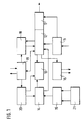
- FIG. 1 shows the block diagram of a vehicle device
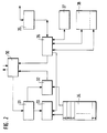
- FIG. 2 shows the block diagram of a beacon device
- FIG. 3 shows a flow diagram
- FIG. 4a, 4b shows a functional diagram of the exemplary embodiment.
- the vehicle guidance and guidance system essentially has two device components: a vehicle device and a fixed beacon device.
- the block diagram of the vehicle device shows, according to FIG. 1, essential functional parts of the invention.
- An input 11 is connected to a control device 12, which has a destination memory 17 for place names and their coordinate pairs.
- the control unit is connected to a display 13 for outputting traffic management information.
- there are connections to the car radio in particular to the memory of the receiving section for the traffic message channels (TMC) and for the speech output 16 to the NF amplifier of the car radio.
- TMC traffic message channels
- a location and navigation system 21 has a compass, wheel sensors, a device for coupling location 15 and a device map matching 14 for determining coordinates by comparing maps.
- a card memory 20 for storing card data transmitted by the beacon.
- the map matching device 14 is connected to the map memory 20.
- a connection to the display 13 is provided to display the map data and the position of the vehicle.
- the map matching device 14 is also connected to the control device 12. Another output of the control device 12 leads to a further buffer for received guide vector chains 18.
- a transmitting / receiving device 19 is connected both to the control unit 12 and to the intermediate memory 18 and card memory 20.
- the transmission / reception device contains known transmission and reception stages for a desired frequency band.
- the transmitting and / or receiving device 30 is initially connected to a request register 31.
- the request register 31 is connected to a name comparator 33, which has access to the street name memory 34.
- Inquiry register 31 is also connected via a vehicle number register 32, which in turn also has access to street name memory 34.
- the vehicle number register 32 is connected to the transmitting device and / or receiving device 30 for transmitting information to the vehicle.
- a control device 36 is connected on the one hand to the transceiver 30 and, on the other hand, to various memories such as guide vector chain memory 37 and the memory 38 for street maps in the near and far range.
- the control device 36 is also connected via an interface 35 to a central computer, not shown, from which a plurality of beacon devices can be controlled.
- the beacon device can be equipped with a receiving part for the radio data system (RDS-TMC), in particular if there is no control by a central computer.
- RDS-TMC radio data system
- FIG. 3 shows a flow diagram for the search for street names in the memory of the beacon device.
- position 40 it is first queried whether there is a request to search for coordinate pairs for a street name. The controller remains in this loop as long as there is no request. If, on the other hand, there is a request, the name of the searched street is stored in a register in position 41. Positions 42 to 44 determine the first, second and third letter of the name. In position 45 the names are searched with this combination of characters. If only one word is found that the three previously determined Contains letters, then the name found is the search word. It is transferred to control unit 36 in position 47 with the associated pair of coordinates. The search is now complete and the program starts again in position 40.
- the fourth letter is determined in position 48 and all names with this combination of characters are searched for. In position 49 there is the same query as in position 46. If there is only one name found, then in position 50 the associated coordinate pair is output to control unit 36 and a return to the beginning of the program in position 40 is initiated.
- the process is repeated by determining the fifth letter in position 51.
- the data found is output in position 53 or the further decoding of a sixth letter in position 54. This search is continued until the name sought is found and its pair of coordinates has been determined.
- the vehicle guidance and guidance system has a modular vehicle device that contains various components such as a location and navigation system (optional), input and output device for destinations, road maps and / or directions in the form of symbol arrows or voice output. It is considered to be particularly advantageous that the entry of the destination (destination and street) takes place in plain text, the coordinates for the searched street being taken from the memory of the beacon device.
- the memory of the beacon device is relatively large, while the vehicle memory, on the other hand, is made relatively small and is therefore inexpensive to manufacture. In order to save storage space, a link to the memory of a car radio can be provided. The use of the is particularly advantageous
- TMC Traffic Message Channel
- the vehicle guidance and route guidance system serves, while largely maintaining anonymity, to support the driver of a vehicle in the search for its destination. In addition to road maps or route suggestions, he receives information about the traffic situation, traffic jams, detours, black ice, etc.
- the system can also be used for the automatic processing of access authorizations, charging of parking or toll fees for roads or spaces subject to toll, since the vehicles cross the street recessed induction loops are detected and can be addressed individually using the beacon devices.
- a driver wants to drive from Hanover to Hildesheim on the 'Blauer Kamp' street. He enters the destination 11 Hildesheim and then the street name 'Blauer Kamp' in plain text into the input unit 11 using a keyboard or a remote control.
- the control device 12 first saves the entered data and shows it on the display 13 for control purposes.
- the control unit 12 of the vehicle recognizes the place name 'Hildesheim' from the first word and searches in the destination memory 17 for the corresponding coordinates for the center of the place of Hildesheim. If a TMC memory is available, the corresponding data is taken from this memory.
- the storage of location data in a TMC memory are known in DE-OS 38 10 180 and DE-OS 39 14 104.
- the vehicle device calculates the target direction and distance according to known trigonometric formulas and shows these values on the display 13. The driver now drives in this direction until he passes a first beacon, for example at the 'Anderten' junction on the A7 motorway.
- the vehicle device now checks whether the local center coordinates (OMK) of Hildesheim are identical to those of the beacon location (Anderten). Since this is not the case, the vehicle device looks for the guide vector chain assigned to the OMK from Hildesheim, in the example A7, from the route tree received by the beacon and displays it on the display 13. A complete map route can also be provided on request. The map can be displayed in various scales.
- the information can be the travel time since the last beacon passed and possibly an individual vehicle identification. This information is sent to the beacon in the time slot of its self-generated random number as a telegram.
- the vehicle device selects a specific random number as the vehicle code and sends it to the beacon.
- the beacon can now send the individual data (e.g. coordinates for the street, house number, hotel, petrol station, etc.) back to the vehicle using this random number.
- the pair of coordinates assigned to the street name is now determined with the aid of the search tree method shown in FIG. 3 and together with the street name and the random vehicle number within a fixed time (approx. 100 ms) transferred back to the vehicle device.
- the guide vector chain is determined and displayed, which leads to the target area in which the street 'Blauer Kamp' is located. If the destination is in the close-up area shown exactly, the guide vector chain leads directly to the selected street (e.g. Blauer Kamp). It is intended to indicate the point of the street that is closest to the route, provided that there is no further information such as house number or hotel etc.
- the selected street e.g. Blauer Kamp
- a guide vector chain can also be sent up to the beacon that is closest to the 'Blauer Kamp' destination.
- the search algorithm for decoding the street 'Blauer Kamp' is described below.
- the transceiver receives the telegram and initially stores it in the request register 31.
- the street name and the vehicle are then decoded in the name comparator 33 or register 32.
- the street name memory 34 has several areas which are arranged alphabetically so that they can be found quickly using the search tree method.
- the program is first started in position 40 and the street name 'Blauer Kamp' is stored in position 41. To save storage space, it is advisable to generally use upper or lower case letters.
- positions 42 to 44 the first three letters of the search word are now decoded, that is 'BLA'.
- position 45 the memory area is now searched in which all the words with the letters 'BLA' are listed.
- the request in position 46 is such that it is only checked whether there are one or more words with this combination of letters. If there is only one word, the search is finished.
- the associated coordinate pairs are now sent to the vehicle via the transmitting / receiving device 30.
- the distance to the target point can be determined.
- the distance can be output both in the voice output 16 via the NF amplifier of the car radio or visually via the data output, the display 13.
- the complete road network and its coordinates are stored in all beacon devices.
- this data can be stored on a compact disc. Since the closest beacon now contains all target data, the vehicle can be directed as follows.
- the sequence of road sections (guide vector chain) leading in the direction of destination can be selected in the beacon and sent to the vehicle. Since the beacon in the vicinity of the vehicle knows the coordinates of the destination, it can transmit a road map to the vehicle which shows the area of the current location of the vehicle and is continuously changed as long as the vehicle is moving in the direction of the destination. If the vehicle comes into the range of another beacon, this beacon takes over the guiding function in the same way and continues the vehicle until the next beacon, and so on, until the vehicle has reached its destination. These guiding vector chains enable the vehicle to be guided successively to the target area. If the vehicle arrives in an area that does not have sufficient beacon infrastructure, then the further navigation is carried out with the location and navigation system 21 with the known coupling location 15. Since in the area of a beacon the coordinates thereof roughly match the coordinates of the location of the Vehicle, this location data can be compared with the location data coupled from the location and navigation system 21 and corrected if necessary. This reduces the error for the positioning and navigation system 21.
- a detailed map is transmitted from the beacon device to the vehicle device in the vicinity of the beacon, target objects such as hotels, train stations, post offices, banks, petrol stations, etc. can also be displayed.
- target objects such as hotels, train stations, post offices, banks, petrol stations, etc.
- the street map is colored, for example main streets, one-way streets or superordinate destination points and the chosen route are highlighted in color.
- the beacon device mentioned in the exemplary embodiment operates in the microwave frequency range at 5.8 GHz.
- Four channels with 5 MHz bandwidth each are available in the range from 5.755 GHz to 5.815 GHz.
- Amplitude modulation at a data rate of 1.125 Mbit / s is used for the data transmission from the beacon device to the vehicle device (FIG. 4a).
- the 5.8 GHz carrier signal is switched on or off depending on the information bit.
- Such a type of modulation is also known as ASK ( a mplitude s shift k eying) or OOK ( o n o ff k eying).
- the beacon device has a flat antenna using stripline technology (microstrip) for transmission and reception.
- the vehicle device is also equipped with a flat stripline antenna.
- the advantage of the chosen modulation method ASK is in particular that the information can be obtained from the microwave signal with a simple envelope detector (diode). A complex receiving device of the vehicle device is therefore not necessary.
- the beacon device sends an unmodulated 5.8 GHz carrier signal (CW signal) in the time slots provided for this purpose.
- CW signal 5.8 GHz carrier signal
- This signal is received by the vehicle device, possibly amplified and fed to a modulator.
- the 5.8 GHz carrier signal is modulated by means of a diode with a frequency of either 1.5 MHz or 2.0 MHz, which is dependent on the information bit, and then sent back to the beacon device (transponder principle).
- the data rate is 125 kbit / s.
- two side bands, in each of which the information as FSK signal f requency s hift eying k
- the beacon device receives the microwave signal modulated by the vehicle device and carries out a frequency conversion into the baseband and then an FSK demodulation.
- the toll system is designed for automatic vehicle recognition and billing. It contains two components, the so-called 'On board unit' (OBU) and the base station installed on the street side.
- OBU 'On board unit
- the OBU and base station exchange coded information via a microwave or infrared communication link, which is required for toll collection.
- the individual sequence is as follows:
- the OBU of the vehicle receives a signal from a first transmitter, which is generally mounted on a first sign bridge or beacon, which activates a demodulator.
- the received signal contains data of the station code, the toll amount and another key word for statistical evaluations.
- the 'on board unit' is now activated.
- the OBU decrypts the received information, subtracts the toll amount, for example for the road to be traveled, from a toll card, which can be inserted into the toll device, for example, as a credit card, and prepares the acknowledgment message.
- the OBU now returns to the stand-by mode.
- a second transmitter which is generally mounted on a subsequent second gantry or beacon, requests the acknowledgment message prepared by the OBU.
- the OBU reactivates and sends the acknowledgment message with two repetitions to a receiver mounted on the same bridge.
- the road device checks the receipt received and ends the process if the result is positive. If the debit is not confirmed, the license plates of the vehicle, preferably from the front and rear, are preferably recorded by a video camera.
- the user is automatically debited from an account.
- the transfer of a personal identifier is required to enable the toll charges to be debited from the user's account.
- Both the control device 12 and 36 of the vehicle and the beacon have a microcomputer with a memory and input / output ports. They are controlled by a program that is structured according to the description.
- the other units such as memory, display etc. are devices known to the person skilled in the art and need not be described in detail.
Claims (19)
- Système de guidage à destination pour véhicules, comprenant un appareil se trouvant dans un véhicule et comportant un appareil d'entrée de données, un appareil de sortie de données, une mémoire pour les noms des lieux de destination, une mémoire de données pour les plans des rues ou les vecteurs de guidage et un premier dispositif d'émission et/ou de réception ; ainsi qu'avec au moins un appareil pour poteau indicateur fixe se trouvant en dehors du véhicule, qui présente un second dispositif d'émission et/ou de réception en liaison avec le premier dispositif d'émission et/ou de réception se trouvant dans le véhicule, et qui. présente une autre mémoire de données dans laquelle sont mis en mémoire de préférence un plan des rues ou des vecteurs de guidage pouvant être transférés à l'appareil situé sur le véhicule
caractérisé en ce quea) l'appareil d'entrée de données (11) de l'appareil situé sur le véhicule, qui sert à l'entrée d'un lieu de destination, de préférence à l'entrée du nom du lieu et/ou du nom de la rue, reçoit ce nom en texte clair,b) la mémoire (17) des lieux de destination contient les coordonnées des centres des lieux (OMK) qui correspondent aux lieux de destination que l'on peut entrer en données,c) l'appareil situé sur le véhicule présente des moyens (12) avec lesquels on peut déterminer un vecteur de destination à partir de la position du véhicule et des coordonnées du centre du lieu (OMK) de destination, et l'envoyer sur un écran (13),d) l'appareil situé sur le poteau indicateur est constitué pour transmettre au véhicule, quand le véhicule passe, les coordonnées du centre du lieu (OMK) associé au poteau indicateur, la paire de coordonnées du lieu où se trouve le poteau indicateur (éventuellement avec un décalage), le réseau numérisé des rues, des informations par surfaces de couleurs et/ou le schéma d'accès à des chaînes vectorielles de guidage du réseau routier,e) l'appareil situé sur le véhicule présente des moyens (12) qui comparent les informations reçues avec les coordonnées du lieu de destination, un vecteur de guidage pouvant être déterminé, en cas d'écart, vers le poteau indicateur suivant placé dans la direction de la destination et, en cas de coïncidence, l'appareil situé dans le poteau indicateur transmettant des parties du plan des rues de la zone de destination et/ou des vecteurs de guidage, vers le point de destination (le nom de la rue ayant été entré), à l'appareil situé sur le véhicule. - Système de guidage à destination pour véhicules selon la revendication 1,
caractérisé en ce que
la mémoire de données (17) de l'appareil situé sur le véhicule est un composant d'un autoradio, de préférence du dispositif pour le canal servant aux messages concernant le trafic (mémoire TMC). - Système de guidage à destination pour véhicules selon la revendication 1 ou 2,
caractérisé en ce que
la mémoire de l'appareil situé dans le poteau indicateur présente d'autres informations en ce qui concerne les justificatifs d'accès et/ou les reçus des montants acquittés pour parquer ou payer les péages. - Système de guidage à destination pour véhicules selon l'une des revendications précédentes,
caractérisé en ce que
le réseau numérisé des rues dans le plan des rues (34) de l'appareil situé dans le poteau indicateur est mis en mémoire jusqu'au second poteau indicateur suivant. - Système de guidage à destination pour véhicules selon l'une des revendications précédentes,
caractérisé en ce que
sur demande d'un véhicule on peut transmettre au véhicule à partir du poteau indicateur une suite de sections de rues (chaîne vectorielle de guidage), suite qui contient le trajet vers le lieu de destination. - Système de guidage à destination pour véhicules selon l'une des revendications précédentes,
caractérisé en ce que
la délivrance des données relatives à la direction à suivre par le véhicule a lieu au moyen de symboles représentés par des flèches et/ou des messages audio. - Système de guidage à destination pour véhicules selon l'une des revendications précédentes,
caractérisé en ce que
la délivrance des données relatives à la direction à suivre a lieu au moyen d'une représentation par carte. - Système de guidage à destination pour véhicules selon la revendication 7,
caractérisé en ce que
la route à suivre ou la chaîne vectorielle de guidage est caractérisée par un tracé coloré. - Système de guidage à destination pour véhicules selon l'une des revendications précédentes,
caractérisé en ce que
dans le véhicule, est prévu un appareil de localisation et de navigation et, à partir des coordonnées reçues par le poteau indicateur, on peut exécuter une correction de la navigation à l'estime. - Système de guidage à destination pour véhicules selon l'une des revendications précédentes, caractérisé en ce que l'appareil situé sur le véhicule et/ou l'appareil situé dans le poteau indicateur présentent un dispositif servant à matérialiser les taxes d'utilisation, de préférence le montant à payer pour les parkings et les péages.
- Système de guidage à destination pour véhicules selon la revendication 10,
caractérisé en ce que
l'appareil situé dans le poteau indicateur enregistre le mouvement d'un véhicule et/ou identifie le véhicule. - Système de guidage à destination pour véhicules selon la revendication 10 ou 11,
caractérisé en ce qu'
on peut introduire dans le dispositif du véhicule une carte de crédit à partir de laquelle on peut débiter le montant dû pour un péage. - Système de guidage à destination pour véhicules selon la revendication 12,
caractérisé en ce que
le débit d'une taxe peut être opéré après validation de la carte de crédit. - Système de guidage à destination pour véhicules selon l'une des revendications 10 à 13,
caractérisé en ce que
dans le cas où la carte de crédit n'est pas valide, une détection automatique des caractéristiques du véhicule a lieu. - Appareil de poteau indicateur pour système de guidage à destination pour véhicules selon l'une des revendications 1 à 14, comportant un dispositif émetteur/récepteur en liaison au moins intermittente avec un dispositif émetteur/récepteur se trouvant dans le véhicule, une mémoire pour une carte numérisée des rues et un appareil de commande,
caractérisé en ce quea) la mémoire (34) contient au moins les autres données suivantes : les coordonnées du centre du lieu (OMK) correspondant au poteau indicateur, la paire de coordonnées du lieu où se trouve le poteau indicateur (éventuellement avec un décalage), des informations par surfaces colorées, le schéma d'accès à des chaînes vectorielles de guidage du réseau routier.b) l'appareil de commande (36) détermine sur la base du lieu de destination, reçu de l'appareil de commande, une suite de sections de rues allant vers la destination (chaîne vectorielle de guidage), etc) l'appareil situé dans le poteau indicateur est constitué de façon à transmettre au véhicule les coordonnées (OMK) du centre du lieu qui correspond au poteau indicateur, la paire de coordonnées du lieu où se trouve le poteau indicateur (éventuellement avec un décalage), un réseau numérisé des rues, des informations par surfaces colorées et/ou, sur demande de l'appareil situé sur le véhicule, le schéma d'accès à la chaîne vectorielle de guidage. - Appareil de poteau indicateur selon la revendication 15,
caractérisé en ce que
l'appareil de poteau indicateur reçoit d'un appareil individuel situé sur le véhicule, à l'intérieur d'une fenêtre de temps, un télégramme portant un numéro aléatoire comme code du véhicule, avec lequel il peut répondre à l'appareil situé sur le véhicule par le même numéro aléatoire. - Appareil situé sur véhicule pour un système de guidage à destination pour véhicules, selon l'une des revendications 1 à 14, comportant un appareil d'entrée de données servant à entrer des signes alphanumériques, un appareil de délivrance de données, une mémoire de données pour les noms des lieux, et un premier dispositif émetteur/récepteur en liaison avec un autre dispositif émetteur/récepteur externe, au moins de façon intermittente,
caractérisé en ce quel'entrée des noms des lieux et des rues a lieu en texte clair, la mémoire de données (17) présente les paires de coordonnées correspondant au nom du centre du lieu entré en données du (OMK), on prévoit des moyens (12) par lesquels on détermine, à partir de la position du véhicule et des coordonnées du centre du lieu (OMK), un vecteur de destination que l'on affiche sur un écran (13), au moyen du dispositif émetteur/récepteur (19) on peut obtenir les coordonnées du nom d'une rue à partir d'un appareil situé sur un poteau indicateur, et l'appareil situé sur le véhicule est agencé pour recevoir au moins l'une des informations suivantes :les coordonnées du centre du lieu (OMK) qui correspond au poteau indicateur, la paire des coordonnées du lieu où se trouve le poteau indicateur (éventuellement avec un décalage), le réseau numérisé des rues au voisinage du poteau indicateur, de préférence jusqu'au second poteau indicateur suivant, des informations par surfaces colorées, et un schéma d'accès allant en direction de la destination, avec une chaîne vectorielle de guidage. - Système de guidage à destination pour véhicules selon l'une des revendications 1 à 14,
caractérisé en ce que
le dispositif émetteur/récepteur (19, 30) de l'appareil situé sur le poteau indicateur et de l'appareil situé sur le véhicule est approprié pour effectuer, dans la zone des micro-ondes, une transmission de données avec une modulation d'amplitude dans le cas d'un taux de données prédéfini, le signal porteur étant branché ou débranché en fonction du bit d'information (amplitude shift keing ou on/off keying). - Système de guidage à destination pour véhicules selon la revendication 18,
caractérisé en ce que
l'appareil situé sur le poteau indicateur et l'appareil situé sur le véhicule sont constitués pour détecter l'information à partir du signal micro-ondes, au moyen d'un redresseur-détecteur d'enveloppe, de préférence une diode.
Applications Claiming Priority (3)
| Application Number | Priority Date | Filing Date | Title |
|---|---|---|---|
| DE4039887A DE4039887A1 (de) | 1990-12-13 | 1990-12-13 | Fahrzeugleit- und zielfuehrungssystem |
| DE4039887 | 1990-12-13 | ||
| PCT/DE1991/000926 WO1992010824A1 (fr) | 1990-12-13 | 1991-11-27 | Systeme de routage et de guidage a destination pour vehicules |
Publications (2)
| Publication Number | Publication Date |
|---|---|
| EP0561818A1 EP0561818A1 (fr) | 1993-09-29 |
| EP0561818B1 true EP0561818B1 (fr) | 1996-11-06 |
Family
ID=6420279
Family Applications (1)
| Application Number | Title | Priority Date | Filing Date |
|---|---|---|---|
| EP91920244A Expired - Lifetime EP0561818B1 (fr) | 1990-12-13 | 1991-11-27 | Systeme de routage et de guidage a destination pour vehicules |
Country Status (7)
| Country | Link |
|---|---|
| US (1) | US5508917A (fr) |
| EP (1) | EP0561818B1 (fr) |
| JP (1) | JP3327333B2 (fr) |
| AT (1) | ATE145082T1 (fr) |
| DE (2) | DE4039887A1 (fr) |
| ES (1) | ES2094238T3 (fr) |
| WO (1) | WO1992010824A1 (fr) |
Cited By (2)
| Publication number | Priority date | Publication date | Assignee | Title |
|---|---|---|---|---|
| EP1255092A2 (fr) | 2001-05-02 | 2002-11-06 | Volkswagen Aktiengesellschaft | Dispositif et procédé pour afficher de l'information dans un véhicule |
| US9269197B2 (en) | 2009-11-23 | 2016-02-23 | Kapsch Trafficcom Ag | Method and device for generating toll information in a road-toll system |
Families Citing this family (81)
| Publication number | Priority date | Publication date | Assignee | Title |
|---|---|---|---|---|
| DE4304838C2 (de) * | 1993-02-17 | 1996-01-25 | Daimler Benz Ag | Vorrichtung zur Bestimmung von Wegebenutzungsgebühren |
| WO1994027256A1 (fr) * | 1993-05-18 | 1994-11-24 | Siemens Aktiengesellschaft | Systeme d'enregistrement de peage s'utilisant dans les rues intra-muros et les zones de circulation |
| DE4332883A1 (de) * | 1993-05-28 | 1994-12-08 | Mannesmann Ag | Einrichtung in einem Fahrzeug zur fahrzeuginternen elektronischen Abrechnung der Nutzung von gebührenpflichtigen Wegstrecken |
| EP0700550B1 (fr) * | 1993-05-28 | 1997-03-05 | MANNESMANN Aktiengesellschaft | Dispositif place dans un vehicule permettant d'effectuer un debit correspondant a l'utilisation de troncons a peage |
| ATE160037T1 (de) * | 1993-05-28 | 1997-11-15 | Mannesmann Ag | Verfahren und einrichtung zur fahrzeuginternen elektronischen abrechnung der nutzung gebührenpflichtiger wegstrecken |
| ATE160038T1 (de) * | 1993-05-28 | 1997-11-15 | Mannesmann Ag | Einrichtung in einem fahrzeug zur abrechnung der nutzung gebührenpflichtiger wegstrecken |
| DE4322188C1 (de) * | 1993-07-03 | 1995-01-12 | Ant Nachrichtentech | Anordnung zum Austauschen von Daten zwischen beweglichen Objekten und Feststationen |
| DE4327385A1 (de) * | 1993-08-14 | 1995-02-16 | Horst Dr Baehring | Anlage zur Erfassung der von einem Kraftfahrzeug zurückgelegten Wegstrecke |
| US5485520A (en) * | 1993-10-07 | 1996-01-16 | Amtech Corporation | Automatic real-time highway toll collection from moving vehicles |
| DE4344433B4 (de) * | 1993-12-24 | 2004-09-30 | T-Mobile Deutschland Gmbh | Erfassungssystem und -verfahren für Autobahngebühren mittels elektronischer Vignette |
| DE4402613A1 (de) * | 1994-01-28 | 1995-08-03 | Deutsche Telekom Mobil | Verfahren und Anordnung zur Ermittlung von Nutzungsgebühren für Verkehrswege und/oder Verkehrsflächen |
| DE4402614A1 (de) * | 1994-01-28 | 1995-08-03 | Deutsche Telekom Mobil | Verfahren zur Ermittlung von Gebühren für die Nutzung von Verkehrswegen durch Fahrzeuge |
| DE4409899A1 (de) * | 1994-03-23 | 1995-09-28 | Ant Nachrichtentech | Anordnung zum Erfassen von Straßenbenutzungsgebühren |
| DE4410450C2 (de) * | 1994-03-25 | 1998-04-30 | Iav Gmbh | Verfahren zur elektronischen Erhebung von Straßenbenutzungsgebühren und zur Kontrolle deren Erhebung bei Straßenfahrzeugen |
| DE4415333A1 (de) * | 1994-05-02 | 1995-11-09 | Iav Gmbh | Fahrzeuggerät für eine elektronische Erhebung von Gebühren beim Parken und Benutzen von Straßen- oder Streckenabschnitten und für die Kontrolle der Gebührenerhebung |
| US5512904A (en) * | 1994-06-13 | 1996-04-30 | Andrew Corporation | Method and apparatus of establishing a vehicle azimuth |
| JP3552171B2 (ja) * | 1994-06-21 | 2004-08-11 | 富士通株式会社 | 料金自動精算システム並びに同システム用無線通信機能付き記憶媒体,同システム用周波数変換装置,同システム用書込装置,同システム用決済装置,同システム用入金装置および同システム用照会装置 |
| US7432830B2 (en) * | 1994-06-24 | 2008-10-07 | Navteq North America, Llc | Electronic navigation system and method |
| JPH0886662A (ja) * | 1994-07-18 | 1996-04-02 | Sumitomo Electric Ind Ltd | 車載の走行経路表示装置、道路情報送信装置、経路案内システムおよびナビゲーションシステムの表示方法 |
| DE4429121C1 (de) † | 1994-08-17 | 1996-02-22 | Siemens Ag | Navigationssystem für ein Fahrzeug |
| JP3045013B2 (ja) * | 1994-09-16 | 2000-05-22 | 住友電気工業株式会社 | ナビゲーション装置 |
| EP0805951B1 (fr) * | 1994-10-07 | 2000-01-19 | MANNESMANN Aktiengesellschaft | Unite d'entree de destination pour systeme de navigation |
| ES2179087T3 (es) * | 1994-11-28 | 2003-01-16 | Vodafone Ag | Procedimiento y sistema para guiar un vehiculo hacia un destino. |
| DE4446644A1 (de) * | 1994-12-19 | 1996-06-20 | Teledrive Telematik Im Verkehr | Anordnung zur automatischen Kontrolle des Zuganges von Fahrzeugen zu einem Verkehrsraum |
| US5842147A (en) * | 1995-03-06 | 1998-11-24 | Aisin Aw Co., Ltd. | Navigation display device which indicates goal and route direction information |
| DE19525291C1 (de) * | 1995-07-03 | 1996-12-19 | Mannesmann Ag | Verfahren und Vorrichtung zur Aktualisierung von digitalen Straßenkarten |
| DE19544382C2 (de) * | 1995-11-15 | 1998-01-15 | Mannesmann Ag | Verfahren und Zielführungseinheit zur sicheren Zielführung eines Fahrzeugs |
| DE19544157C2 (de) * | 1995-11-14 | 1998-02-26 | Mannesmann Ag | Verfahren und Zielführungseinheit zur sicheren Zielführung eines Fahrzeugs |
| DE19544381C2 (de) * | 1995-11-15 | 1997-12-18 | Mannesmann Ag | Verfahren und Zielführungseinheit zur sicheren Zielführung eines Fahrzeugs |
| US5790973A (en) * | 1995-12-19 | 1998-08-04 | Prince Corporation | Last exit warning system |
| JP3216514B2 (ja) * | 1996-01-31 | 2001-10-09 | 株式会社デンソー | 情報サービス装置 |
| DE69632242T2 (de) * | 1996-02-01 | 2005-04-14 | Aisin AW Co., Ltd., Anjo | Fahrzeugnavigationssystem und Verfahren zur Eingabe und Speicherung von Kursänderungspunkten |
| DE19608538C1 (de) * | 1996-03-06 | 1997-05-15 | Grundig Emv | Verkehrsleit- und Informationssystem |
| DE29610677U1 (de) * | 1996-06-18 | 1996-09-12 | Terbrack Leo Dipl Ing | Anordnung zur Anzeige von Verkehrshinweisen |
| DE19634340A1 (de) * | 1996-08-24 | 1998-02-26 | Bosch Gmbh Robert | Verfahren und Empfänger zur Übermittlung von Informationen für Straßennutzungsgebühren und Empfänger |
| WO1998027526A1 (fr) * | 1996-12-16 | 1998-06-25 | Mannesmann Ag | Procede pour transmettre entre un central d'informations routieres et un terminal monte dans un vehicule des informations routieres qui constituent une aide a la navigation et qui definissent un trajet propose d'un vehicule dans un reseau routier, central d'informations routieres et terminal |
| KR100291088B1 (ko) * | 1997-02-07 | 2001-09-17 | 가시오 가즈오 | 이동단말장치에정보를제공하기위한네트워크시스템 |
| FR2761837B1 (fr) * | 1997-04-08 | 1999-06-11 | Sophie Sommelet | Dispositif d'aide a la navigation ayant une architecture distribuee basee sur internet |
| US6148261A (en) * | 1997-06-20 | 2000-11-14 | American Calcar, Inc. | Personal communication system to send and receive voice data positioning information |
| DE19734365A1 (de) * | 1997-08-08 | 1999-02-18 | Grundig Ag | Navigationssystem für ein Kraftfahrzeug |
| DE19747230A1 (de) | 1997-10-25 | 1999-05-12 | Bosch Gmbh Robert | Verfahren zur Berücksichtigung ergänzender Verkehrsinformationen in einer fahrzeugfesten Zielführungseinrichtung |
| US9075136B1 (en) | 1998-03-04 | 2015-07-07 | Gtj Ventures, Llc | Vehicle operator and/or occupant information apparatus and method |
| JP2994347B1 (ja) * | 1998-08-07 | 1999-12-27 | 三菱電機株式会社 | 車載装置 |
| US20040215387A1 (en) | 2002-02-14 | 2004-10-28 | Matsushita Electric Industrial Co., Ltd. | Method for transmitting location information on a digital map, apparatus for implementing the method, and traffic information provision/reception system |
| DE19938345C1 (de) * | 1999-08-13 | 2001-02-15 | Isocom Automationssysteme Gmbh | Verfahren und Vorrichtung zur Erfassung der Position von einem Fahrzeug in einem vorgegebenen Bereich, insbesondere einer Lagereinrichtung, sowie Lagerverwaltungsverfahren und -system |
| JP3481168B2 (ja) | 1999-08-27 | 2003-12-22 | 松下電器産業株式会社 | デジタル地図の位置情報伝達方法 |
| KR100845568B1 (ko) * | 1999-10-19 | 2008-07-10 | 아메리칸 캘카어 인코포레이티드 | 사용자 선호도에 기초한 효과적인 내비게이션 기술 |
| JP3698004B2 (ja) | 2000-03-15 | 2005-09-21 | 株式会社デンソー | 自動料金収受システムに使用される移動体無線通信装置 |
| GB2360588B (en) * | 2000-03-23 | 2004-04-07 | Yeoman Group Plc | Navigation system |
| GB0011797D0 (en) * | 2000-05-16 | 2000-07-05 | Yeoman Group Plc | Improved vehicle routeing |
| JP3791314B2 (ja) | 2000-09-14 | 2006-06-28 | 株式会社デンソー | 車載装置、及びサービス提供システム |
| US20020059532A1 (en) * | 2000-11-16 | 2002-05-16 | Teruaki Ata | Device and method for authentication |
| JP5041638B2 (ja) | 2000-12-08 | 2012-10-03 | パナソニック株式会社 | デジタル地図の位置情報伝達方法とそれに使用する装置 |
| JP4663136B2 (ja) | 2001-01-29 | 2011-03-30 | パナソニック株式会社 | デジタル地図の位置情報伝達方法と装置 |
| JP4749594B2 (ja) * | 2001-04-27 | 2011-08-17 | パナソニック株式会社 | デジタル地図の位置情報伝達方法 |
| JP4230132B2 (ja) | 2001-05-01 | 2009-02-25 | パナソニック株式会社 | デジタル地図の形状ベクトルの符号化方法と位置情報伝達方法とそれを実施する装置 |
| US6356208B1 (en) * | 2001-05-04 | 2002-03-12 | Chunghwatelecom Co., Ltd. | Structure for a car sensing infrared communication device placed over a lane of a freeway |
| DE10122448A1 (de) * | 2001-05-09 | 2002-11-14 | Bosch Gmbh Robert | Verfahren zum Betrieb eines Navigationssystems für ein Fahrzeug, insbesondere ein Kraftfahrzeug, und Navigationssystem |
| DE10149991A1 (de) * | 2001-10-11 | 2003-04-30 | Vodafone Ag | Erfassungssystem für Fahrzeuge mit GPS |
| GB2384354A (en) * | 2002-01-18 | 2003-07-23 | Yeoman Group Plc | Navigation System |
| JP2004085485A (ja) * | 2002-08-28 | 2004-03-18 | Honda Motor Co Ltd | 車両ナビゲーションサーバ及びこれを利用する車両ナビゲーション装置、車両ナビゲーションシステム |
| US8700308B2 (en) | 2006-03-31 | 2014-04-15 | Volkswagen Ag | Navigation system for a motor vehicle |
| US8554463B2 (en) | 2006-03-31 | 2013-10-08 | Volkswagen Ag | Navigation system for a motor vehicle |
| US9052214B2 (en) | 2006-05-22 | 2015-06-09 | Volkswagen Ag | Navigation system for a motor vehicle, method for operating a navigation system and motor vehicle including a navigation system |
| US9478133B2 (en) | 2006-03-31 | 2016-10-25 | Volkswagen Ag | Motor vehicle and navigation arrangement for a motor vehicle |
| US20070233371A1 (en) | 2006-03-31 | 2007-10-04 | Arne Stoschek | Navigation system for a motor vehicle |
| US20080303649A1 (en) * | 2006-12-28 | 2008-12-11 | Vodafone Group Plc | Method for improving traffic safety by means of using beacons |
| ES2326057B1 (es) * | 2006-12-28 | 2010-06-25 | Vodafone España, S.A. | Metodo para la mejora de la seguridad del trafico mediante el uso de balizas. |
| WO2008154727A1 (fr) | 2007-06-21 | 2008-12-24 | Harris Korn | Système et procédé de localisation d'un véhicule |
| JP5115182B2 (ja) * | 2007-12-21 | 2013-01-09 | 株式会社Jvcケンウッド | 車載器及び情報配信システム |
| JP5169207B2 (ja) * | 2007-12-21 | 2013-03-27 | 株式会社Jvcケンウッド | 路車間通信システム |
| JP2009153018A (ja) * | 2007-12-21 | 2009-07-09 | Kenwood Corp | 情報配信システム及び車載器 |
| JP2009151720A (ja) * | 2007-12-21 | 2009-07-09 | Kenwood Corp | 道路交通情報提供システム、道路交通情報提供装置、道路交通情報提供方法およびプログラム |
| JP5056401B2 (ja) * | 2007-12-21 | 2012-10-24 | 株式会社Jvcケンウッド | 車載器,出力可否判定方法,道路通信システムおよびプログラム |
| JP2009151716A (ja) * | 2007-12-21 | 2009-07-09 | Kenwood Corp | 道路交通情報提供システム、道路交通情報提供装置、道路交通情報提供方法およびプログラム |
| US8949069B2 (en) * | 2009-12-16 | 2015-02-03 | Intel Corporation | Position determination based on propagation delay differences of multiple signals received at multiple sensors |
| AU2013308645B2 (en) * | 2012-08-31 | 2017-08-17 | Autonomous Tractor Corporation | Navigation system and method |
| WO2014193334A1 (fr) | 2013-05-26 | 2014-12-04 | Intel Corporation | Appareil, système et procédé de communication d'informations de positionnement |
| US9432115B2 (en) | 2013-07-10 | 2016-08-30 | Intel Corporation | Apparatus, system and method of communicating positioning transmissions |
| US10302445B2 (en) * | 2016-02-01 | 2019-05-28 | Ford Global Technologies, Llc | System and method for navigation guidance using a wireless network |
| CN106875675B (zh) * | 2017-04-28 | 2023-01-10 | 南京云计趟信息技术有限公司 | 一种快速识别渣土车偏离行驶的检测系统和方法 |
Family Cites Families (10)
| Publication number | Priority date | Publication date | Assignee | Title |
|---|---|---|---|---|
| DE2936062C2 (de) | 1979-09-06 | 1985-11-07 | Siemens AG, 1000 Berlin und 8000 München | Leitsystem für den Individualverkehr und Verfahren zur Übertragung von Leitinformationen |
| US4420682A (en) * | 1982-03-22 | 1983-12-13 | The United States Of America As Represented By The Secretary Of The Army | Interactive map information exchange system |
| US4914605A (en) * | 1984-10-22 | 1990-04-03 | Etak, Inc. | Apparatus and method for displaying a map |
| DE3905493C5 (de) * | 1989-02-23 | 2013-08-29 | Robert Bosch Gmbh | Ortungs- und Navigationssystem für Landfahrzeuge |
| DE3633881A1 (de) * | 1986-10-04 | 1988-04-07 | Bosch Gmbh Robert | Empfaenger fuer verkehrsfunksendungen |
| GB8726312D0 (en) | 1987-11-10 | 1987-12-16 | Plessey Co Plc | Road vehicle route selection & guidance |
| US5187810A (en) * | 1988-06-10 | 1993-02-16 | Oki Electric Industry Co., Ltd. | Route guidance system for provding a mobile station with optimum route data in response to a guidance request together with base station data indicative of an identification of a base station |
| DE3820639A1 (de) * | 1988-06-18 | 1989-12-21 | Bosch Gmbh Robert | Stromsparende stand-by-funktion in tmc-empfaengern |
| US5101200A (en) * | 1989-06-09 | 1992-03-31 | Swett Paul H | Fast lane credit card |
| US5274560A (en) * | 1990-12-03 | 1993-12-28 | Audio Navigation Systems, Inc. | Sensor free vehicle navigation system utilizing a voice input/output interface for routing a driver from his source point to his destination point |
-
1990
- 1990-12-13 DE DE4039887A patent/DE4039887A1/de not_active Withdrawn
-
1991
- 1991-11-27 DE DE59108334T patent/DE59108334D1/de not_active Expired - Fee Related
- 1991-11-27 WO PCT/DE1991/000926 patent/WO1992010824A1/fr active IP Right Grant
- 1991-11-27 EP EP91920244A patent/EP0561818B1/fr not_active Expired - Lifetime
- 1991-11-27 AT AT91920244T patent/ATE145082T1/de not_active IP Right Cessation
- 1991-11-27 ES ES91920244T patent/ES2094238T3/es not_active Expired - Lifetime
- 1991-11-27 JP JP50026092A patent/JP3327333B2/ja not_active Expired - Fee Related
- 1991-11-27 US US08/039,336 patent/US5508917A/en not_active Expired - Lifetime
Cited By (2)
| Publication number | Priority date | Publication date | Assignee | Title |
|---|---|---|---|---|
| EP1255092A2 (fr) | 2001-05-02 | 2002-11-06 | Volkswagen Aktiengesellschaft | Dispositif et procédé pour afficher de l'information dans un véhicule |
| US9269197B2 (en) | 2009-11-23 | 2016-02-23 | Kapsch Trafficcom Ag | Method and device for generating toll information in a road-toll system |
Also Published As
| Publication number | Publication date |
|---|---|
| DE59108334D1 (de) | 1996-12-12 |
| ATE145082T1 (de) | 1996-11-15 |
| US5508917A (en) | 1996-04-16 |
| JPH06503193A (ja) | 1994-04-07 |
| JP3327333B2 (ja) | 2002-09-24 |
| WO1992010824A1 (fr) | 1992-06-25 |
| ES2094238T3 (es) | 1997-01-16 |
| EP0561818A1 (fr) | 1993-09-29 |
| DE4039887A1 (de) | 1992-06-17 |
Similar Documents
| Publication | Publication Date | Title |
|---|---|---|
| EP0561818B1 (fr) | Systeme de routage et de guidage a destination pour vehicules | |
| EP0697580B2 (fr) | Système de navigation pour un véhicule | |
| EP0805952B1 (fr) | Dispositif de guidage de personnes a destination | |
| DE60114499T2 (de) | Mobilfunksystem für ein automatisches Mautgebühreneinzugssystem | |
| EP1198696B1 (fr) | Procede et dispositif pour la transmission d'informations de navigation d'une centrale de donnees a un systeme de navigation monte dans un vehicule | |
| AT411500B (de) | Duales mautsystem | |
| DE19623666C1 (de) | Verfahren zur dynamischen Routenempfehlung | |
| DE2936062A1 (de) | Leitsystem fuer den individualverkehr | |
| EP0802509B1 (fr) | Procédé de taxation automatique de péage routier | |
| WO2001011571A1 (fr) | Systeme de peage pour le prelevement central de taxes dues par des vehicules utilisant un reseau routier a peage | |
| DE10200716A1 (de) | Radiokommunikationsvorrichtung | |
| EP1200938B8 (fr) | Unite de controle permettant de verifier que des appareils de peage montes dans des vehicules fonctionnent correctement | |
| EP1630747A2 (fr) | Système et méthode de perception des droits de péage | |
| EP0715289B1 (fr) | Procédé et système pour le guidage d'un véhicule | |
| EP1133675A1 (fr) | Dispositif et procede de navigation | |
| EP0538514B1 (fr) | Système de renseignement et de guidage destiné au transport en commun | |
| WO1992017867A1 (fr) | Procede et dispositif de representation de donnees geographiques | |
| DE10207961A1 (de) | Echtzeit-System für Berichte zur Verkehrslage | |
| DE102007017257A1 (de) | Verfahren und System zum Bereitstellen teilnehmerspezifischer Dienste | |
| WO1996000960A1 (fr) | Systeme electronique d'information et d'indication d'horaires pour transports publics | |
| DE102017216124A1 (de) | Verfahren zur Erzeugung einer Verkehrsleitinformation und Verkehrsleitsystem | |
| DE19634340A1 (de) | Verfahren und Empfänger zur Übermittlung von Informationen für Straßennutzungsgebühren und Empfänger | |
| DE102009042470A1 (de) | Anordnung und Verfahren zur Erfassung von Gebühren auf mautpflichtigen Straßen | |
| EP1203354B1 (fr) | Procede pour percevoir des taxes de maniere automatique et dispositif a cet effet | |
| EP1640923A1 (fr) | Méthode pour l'activation automatique et pour la mise à disposition de services dépendant de la localisation ainsi qu'un dispositif mobile, un module d'identification et un système |
Legal Events
| Date | Code | Title | Description |
|---|---|---|---|
| PUAI | Public reference made under article 153(3) epc to a published international application that has entered the european phase |
Free format text: ORIGINAL CODE: 0009012 |
|
| 17P | Request for examination filed |
Effective date: 19930508 |
|
| AK | Designated contracting states |
Kind code of ref document: A1 Designated state(s): AT BE CH DE ES FR GB IT LI NL SE |
|
| 17Q | First examination report despatched |
Effective date: 19941108 |
|
| GRAG | Despatch of communication of intention to grant |
Free format text: ORIGINAL CODE: EPIDOS AGRA |
|
| GRAH | Despatch of communication of intention to grant a patent |
Free format text: ORIGINAL CODE: EPIDOS IGRA |
|
| GRAH | Despatch of communication of intention to grant a patent |
Free format text: ORIGINAL CODE: EPIDOS IGRA |
|
| GRAA | (expected) grant |
Free format text: ORIGINAL CODE: 0009210 |
|
| AK | Designated contracting states |
Kind code of ref document: B1 Designated state(s): AT BE CH DE ES FR GB IT LI NL SE |
|
| REF | Corresponds to: |
Ref document number: 145082 Country of ref document: AT Date of ref document: 19961115 Kind code of ref document: T |
|
| REG | Reference to a national code |
Ref country code: CH Ref legal event code: NV Representative=s name: SCINTILLA AG, DIREKTION |
|
| REF | Corresponds to: |
Ref document number: 59108334 Country of ref document: DE Date of ref document: 19961212 |
|
| ET | Fr: translation filed | ||
| REG | Reference to a national code |
Ref country code: ES Ref legal event code: FG2A Ref document number: 2094238 Country of ref document: ES Kind code of ref document: T3 |
|
| ITF | It: translation for a ep patent filed |
Owner name: STUDIO JAUMANN |
|
| GBT | Gb: translation of ep patent filed (gb section 77(6)(a)/1977) |
Effective date: 19970123 |
|
| PLBE | No opposition filed within time limit |
Free format text: ORIGINAL CODE: 0009261 |
|
| STAA | Information on the status of an ep patent application or granted ep patent |
Free format text: STATUS: NO OPPOSITION FILED WITHIN TIME LIMIT |
|
| 26N | No opposition filed | ||
| REG | Reference to a national code |
Ref country code: GB Ref legal event code: IF02 |
|
| PGFP | Annual fee paid to national office [announced via postgrant information from national office to epo] |
Ref country code: CH Payment date: 20081124 Year of fee payment: 18 Ref country code: NL Payment date: 20081120 Year of fee payment: 18 |
|
| PGFP | Annual fee paid to national office [announced via postgrant information from national office to epo] |
Ref country code: AT Payment date: 20081120 Year of fee payment: 18 Ref country code: ES Payment date: 20081121 Year of fee payment: 18 |
|
| PGFP | Annual fee paid to national office [announced via postgrant information from national office to epo] |
Ref country code: SE Payment date: 20081124 Year of fee payment: 18 Ref country code: IT Payment date: 20081126 Year of fee payment: 18 Ref country code: BE Payment date: 20081203 Year of fee payment: 18 |
|
| PGFP | Annual fee paid to national office [announced via postgrant information from national office to epo] |
Ref country code: FR Payment date: 20081118 Year of fee payment: 18 |
|
| PGFP | Annual fee paid to national office [announced via postgrant information from national office to epo] |
Ref country code: DE Payment date: 20090126 Year of fee payment: 18 |
|
| PGFP | Annual fee paid to national office [announced via postgrant information from national office to epo] |
Ref country code: GB Payment date: 20081121 Year of fee payment: 18 |
|
| BERE | Be: lapsed |
Owner name: ROBERT *BOSCH G.M.B.H. Effective date: 20091130 |
|
| REG | Reference to a national code |
Ref country code: NL Ref legal event code: V1 Effective date: 20100601 |
|
| EUG | Se: european patent has lapsed | ||
| REG | Reference to a national code |
Ref country code: CH Ref legal event code: PL |
|
| GBPC | Gb: european patent ceased through non-payment of renewal fee |
Effective date: 20091127 |
|
| REG | Reference to a national code |
Ref country code: FR Ref legal event code: ST Effective date: 20100730 |
|
| PG25 | Lapsed in a contracting state [announced via postgrant information from national office to epo] |
Ref country code: AT Free format text: LAPSE BECAUSE OF NON-PAYMENT OF DUE FEES Effective date: 20091127 |
|
| PG25 | Lapsed in a contracting state [announced via postgrant information from national office to epo] |
Ref country code: NL Free format text: LAPSE BECAUSE OF NON-PAYMENT OF DUE FEES Effective date: 20100601 Ref country code: BE Free format text: LAPSE BECAUSE OF NON-PAYMENT OF DUE FEES Effective date: 20091130 Ref country code: CH Free format text: LAPSE BECAUSE OF NON-PAYMENT OF DUE FEES Effective date: 20091130 Ref country code: FR Free format text: LAPSE BECAUSE OF NON-PAYMENT OF DUE FEES Effective date: 20091130 Ref country code: LI Free format text: LAPSE BECAUSE OF NON-PAYMENT OF DUE FEES Effective date: 20091130 |
|
| PG25 | Lapsed in a contracting state [announced via postgrant information from national office to epo] |
Ref country code: DE Free format text: LAPSE BECAUSE OF NON-PAYMENT OF DUE FEES Effective date: 20100601 |
|
| PG25 | Lapsed in a contracting state [announced via postgrant information from national office to epo] |
Ref country code: GB Free format text: LAPSE BECAUSE OF NON-PAYMENT OF DUE FEES Effective date: 20091127 |
|
| REG | Reference to a national code |
Ref country code: ES Ref legal event code: FD2A Effective date: 20110309 |
|
| PG25 | Lapsed in a contracting state [announced via postgrant information from national office to epo] |
Ref country code: IT Free format text: LAPSE BECAUSE OF NON-PAYMENT OF DUE FEES Effective date: 20091127 |
|
| PG25 | Lapsed in a contracting state [announced via postgrant information from national office to epo] |
Ref country code: SE Free format text: LAPSE BECAUSE OF NON-PAYMENT OF DUE FEES Effective date: 20091128 |
|
| PG25 | Lapsed in a contracting state [announced via postgrant information from national office to epo] |
Ref country code: ES Free format text: LAPSE BECAUSE OF NON-PAYMENT OF DUE FEES Effective date: 20110308 |
|
| PG25 | Lapsed in a contracting state [announced via postgrant information from national office to epo] |
Ref country code: ES Free format text: LAPSE BECAUSE OF NON-PAYMENT OF DUE FEES Effective date: 20091128 |