EP0560889B1 - Einstellbares, dentales implantatsystem - Google Patents
Einstellbares, dentales implantatsystem Download PDFInfo
- Publication number
- EP0560889B1 EP0560889B1 EP92901539A EP92901539A EP0560889B1 EP 0560889 B1 EP0560889 B1 EP 0560889B1 EP 92901539 A EP92901539 A EP 92901539A EP 92901539 A EP92901539 A EP 92901539A EP 0560889 B1 EP0560889 B1 EP 0560889B1
- Authority
- EP
- European Patent Office
- Prior art keywords
- anchor
- support
- implant
- alignable
- alignment
- Prior art date
- Legal status (The legal status is an assumption and is not a legal conclusion. Google has not performed a legal analysis and makes no representation as to the accuracy of the status listed.)
- Expired - Lifetime
Links
Images


Classifications
-
- A—HUMAN NECESSITIES
- A61—MEDICAL OR VETERINARY SCIENCE; HYGIENE
- A61C—DENTISTRY; APPARATUS OR METHODS FOR ORAL OR DENTAL HYGIENE
- A61C13/00—Dental prostheses; Making same
- A61C13/225—Fastening prostheses in the mouth
- A61C13/265—Sliding or snap attachments
- A61C13/2656—Snap attachments
-
- A—HUMAN NECESSITIES
- A61—MEDICAL OR VETERINARY SCIENCE; HYGIENE
- A61C—DENTISTRY; APPARATUS OR METHODS FOR ORAL OR DENTAL HYGIENE
- A61C8/00—Means to be fixed to the jaw-bone for consolidating natural teeth or for fixing dental prostheses thereon; Dental implants; Implanting tools
- A61C8/0048—Connecting the upper structure to the implant, e.g. bridging bars
- A61C8/005—Connecting devices for joining an upper structure with an implant member, e.g. spacers
- A61C8/0069—Connecting devices for joining an upper structure with an implant member, e.g. spacers tapered or conical connection
-
- A—HUMAN NECESSITIES
- A61—MEDICAL OR VETERINARY SCIENCE; HYGIENE
- A61C—DENTISTRY; APPARATUS OR METHODS FOR ORAL OR DENTAL HYGIENE
- A61C8/00—Means to be fixed to the jaw-bone for consolidating natural teeth or for fixing dental prostheses thereon; Dental implants; Implanting tools
- A61C8/0048—Connecting the upper structure to the implant, e.g. bridging bars
- A61C8/005—Connecting devices for joining an upper structure with an implant member, e.g. spacers
- A61C8/0054—Connecting devices for joining an upper structure with an implant member, e.g. spacers having a cylindrical implant connecting part
-
- A—HUMAN NECESSITIES
- A61—MEDICAL OR VETERINARY SCIENCE; HYGIENE
- A61C—DENTISTRY; APPARATUS OR METHODS FOR ORAL OR DENTAL HYGIENE
- A61C8/00—Means to be fixed to the jaw-bone for consolidating natural teeth or for fixing dental prostheses thereon; Dental implants; Implanting tools
- A61C8/0048—Connecting the upper structure to the implant, e.g. bridging bars
- A61C8/005—Connecting devices for joining an upper structure with an implant member, e.g. spacers
- A61C8/0057—Connecting devices for joining an upper structure with an implant member, e.g. spacers with elastic means
-
- A—HUMAN NECESSITIES
- A61—MEDICAL OR VETERINARY SCIENCE; HYGIENE
- A61C—DENTISTRY; APPARATUS OR METHODS FOR ORAL OR DENTAL HYGIENE
- A61C8/00—Means to be fixed to the jaw-bone for consolidating natural teeth or for fixing dental prostheses thereon; Dental implants; Implanting tools
- A61C8/0048—Connecting the upper structure to the implant, e.g. bridging bars
- A61C8/005—Connecting devices for joining an upper structure with an implant member, e.g. spacers
- A61C8/006—Connecting devices for joining an upper structure with an implant member, e.g. spacers with polygonal positional means, e.g. hexagonal or octagonal
Definitions
- the present invention relates to an endosteal implant assembly and more particularly, to a novel abutment/anchor, hereinafter referred to as anchor, for adjustably supporting one or more prosthetic teeth or appliances at a desirable orientation relative to the path of insertion of the restoration.
- the present invention is particularly suited, but not limited, to use with patient-removable restorations.
- a prosthetic implant attachment system as well as an anchor for a dental prosthesis as defined in the preamble of claims 1 and 10, respectively, are disclosed in US-A-4 854 872.
- a dental prosthesis for replacing one or more missing teeth may be accomplished by placement of one or more dental implants in the jawbone and corresponding number of anchors to which the dental prosthesis is secured thereto.
- the anchor is normally screwed or bonded into the implant.
- the implant is generally made from a titanium alloy or other rigid materials which are non-reactive with human tissue or fluid.
- the angle of a dental anchor must be aligned with the intended angle of the path of insertion of the restoration and must be maintained from abutment to abutment, in cases where multiple implants are employed, to facilitate a smooth and non-traumatic insertion and function of a removable or a fixed appliance.
- the determination of the most desirable path of insertion of the appliance may be governed by factors such as the position of adjacent natural teeth, arc of closure, ridge contour and the patient's dexterity.
- Prior inventions for adjustably aligning the prosthetic tooth are disclosed, for example, in U.S.
- a wedge shaped collar having an angled upper surface is placed around the angled shaft and the upper surface is positioned to coincide with the angle of the shaft so that the free end of the shaft extends perpendicularly from the angled surface.
- a prosthetic tooth anchor is threaded on the free end of the shaft to secure the collar in a set orientation.
- Linkow also discloses an alternative embodiment of aligning a prosthetic tooth, in which, instead of the angled shaft and collar, an intermediary anchor having a ball and socket joint is threaded in the implant.
- a bolt, which is attached to a prosthetic tooth anchor, is screwed completely through the ball to fix the position of the ball relative to the socket once an alignment has been accomplished.
- Linden utilizes a hexagonally-shaped intermediary anchor which is fastened to a complementary hexagonal bore formed in a dental implant.
- a prosthetic tooth anchor is adjustably secured to the intermediary anchor with a screw.
- the intermediary and the prosthetic tooth anchors function much like a ball and socket joint when the screw is loosened. That is, the prosthetic tooth anchor may move universally within the intermediary anchor.
- the intermediary anchor and the prosthetic anchor may then be entirely removed from the implant.
- the screw is then tightened to immobilize the prosthetic support anchor relative to the intermediary anchor.
- the prosthetic support anchor with a prosthetic tooth formed thereon and the intermediary anchor is then placed back into the implant and secured thereto by a conventional means such as bonding or by a mechanical means.
- US-A-4,854,872 discloses a base member designed to seat on the upper end of an implant cylinder embedded in the jawbone, and an angled prosthetic head designed to seat on the base member and to form a mounting for seating a prosthesis.
- the implant cylinder defines an internal screw thread and a threaded fastener is utilized to secure the base member and prosthetic head to the cylinder. Relative rotation between the parts is prevented by providing projections and corresponding indents in adjacent parts, and the projections and indents may take various forms, for example, hexagonal or octagonal. This permits the head to be locked in any one of a plurality of fixed, indexed positions relative to the base member. Adjustment requires the threaded fastener to be loosened to permit separation of the respective projection and indent and relative rotation thereof.
- US Patent 4,934,935 to Edwards also employs a conventional implant technique for setting an implant in the jawbone.
- An intermediary anchor is temporarily plugged into the implant and is properly positioned therein by rotating the anchor which is set at a predetermined angle.
- the anchor is then bonded to the implant once properly positioned.
- a prosthetic tooth anchor is then screwed into the angled intermediary anchor for supporting a prosthetic tooth thereon.
- the use of dental implants has seen a tremendous growth.
- the technique of placement of the implants into the jawbone has been refined and the success rate has been excellent.
- the implants represent an exciting treatment option.
- the present invention was devised with the intention to simplify and make more effective the procedures for the operator and to further increase the success rate for the patients.
- the implant does not have to be exactly placed and/or aligned with the desired path of insertion of the dental appliance since the anchor can be independently adjusted to facilitate the alignment.
- the anchor has been formed so that a dental prothesis may be taken completely off the anchor and placed back on the anchor by the user.
- the present invention comprises an implant utilizing a conventional osseointegration technique for firmly anchoring the implant in the jawbone and a two-piece anchor.
- One piece is configured as a dental prosthesis support for removably supporting one or more prosthetic teeth and a second piece is configured as a threaded base portion for semi-permanently attaching to the implant.
- the support is removably and adjustably situated within the threaded base portion so that the support is rotatable within the threaded base portion about the longitudinal axis of the threaded base portion.
- the support has an upper protrusion that is angled with respect to a lower portion thereof. By rotating the support with respect to the threaded base portion, a plurality of alignments can be achieved.
- the support comes with various preselected angles so that various alignments can be realized using various selections of the pre-angled supports.
- unique alignment handles are employed to facilitate an intra-oral assessment of functional alignment between two or more anchors.
- the handles also simplify the insertion of the implant assembly into the implant by providing an extension surface for easy grasping and handling of the assembly.
- the handles may be used either to carry the support with its base snapped onto it to the implant in the mouth, or the support alone to the base already situated in the implant.
- one or more implants are initially strategically placed in the jawbone. After the implants are fully integrated, i.e, after the jawbone completely grows around the implants, a base portion with or without a prosthetic support and alignment handle seated therein is threaded into each implant and fully tightened thereto. If a prosthetic support of a desired angle and an alignment handle have not been previously seated in each base, an alignment handle is snapped into each angled prosthetic support and the alignment handle with the angled prosthetic support is then seated in each base portion. Each prosthetic support with its alignment handle is rotated about the longitudinal axis of the base until the best alignment is achieved. If a visual assessment of mutual alignment of the handles snapped in the anchors does not indicate a satisfactory alignment even if the supports are adjusted, a differently angled prosthetic support may be used in various bases to achieve a satisfactory alignment of all anchors.
- the alignment of the support with respect to the base is marked so as to capture the desired orientation.
- the support is then separated from the base portion.
- the base portion and the support are cleaned and bonded utilizing a conventional bonding technique, with the support being aligned with respect to the base portion using the mark to properly orient the support.
- the support and the threaded base portion now as one piece, is ready to be threaded back into the implant.
- the threads of the base are coated with a medical grade silicone adhesive to seal the threads from oral fluids to eliminate bacterial growth and to prevent the anchor from loosening from the implant.
- the adhesive properties of this type of silicone material are such that it is possible to allow deliberate unthreading of the anchor from the implant if replacement is required. When the anchor is completely threaded into the implant, the precision threading assures that the anchor will be returned to the exact same position as during the marking step.
- the support comprises a female eyelet, similar to the type disclosed in U.S. Patent 4,540,367, whereby a dental prothesis having one or more prosthetic teeth is removably attached to one or more female eyelets.
- the prosthesis has one or more nylon male caps embedded thereto, each male cap seating on one of the female eyelets, as disclosed in U.S. Patent 4,540,367.
- the metal female eyelet of the anchor is protected from wear by the nylon-to-metal contact of the snap-in nylon male.
- the female eyelet or any other portion of the anchor suffer any wear or damage, it can be readily replaced with a new anchor by simply removing the dental prosthesis and unscrewing the anchor from the implant.
- the new anchor is aligned using the alignment technique as described above.
- the object of the invention is to provide a simple and yet effective means for aligning anchors of an endosteal implant.
- Another object of the invention is to provide an anchor that is readily removable and replaceable with respect to the endosteal implant.
- Another object of the invention is to provide a dental prosthesis that is readily removable and reattachable to one or more anchors of the corresponding number of endosteal implants.
- Still another object of the invention is to enable the bonding of a prosthetic support to the base support in a dry environment.
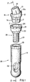
- Fig. 1 is a perspective view of the present dental implant unit in unassembled form.
- Fig. 2 is a cross sectional view taken along the line 2-2 of Fig. 1, with the dental assembly unit in assembled form.
- Fig. 3 is a front view of the angled support for mounting a dental prothesis thereto.
- Fig. 4 is a perspective view of the angled support, showing the slotted lower portion thereof.
- Fig. 5 is a perspective view of the angled support with a removable nylon cap placed on the upper portion thereof.
- Fig. 6 is a front elevational cross-sectional view taken along the line 6-6 of Fig. 5.
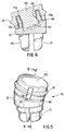
- Fig. 7 is a partially cross-sectioned view of the alignment handle seated on the angled support.
- Fig. 1 shows a dental implant unit in unassembled form.
- the dental implant comprises an implant 30 and an anchor having a base 20 and an angled support 10.
- the implant has an elongated body 31, which is preferably made of a titanium alloy or other suitable materials which do not react with human tissue or fluid. Openings 32 are formed in the lower portion of the implant.
- a threaded cavity 33 is formed from the upper end of the implant for attaching the base. The purpose of the openings 32 is for the jawbone to grow thereinto and form a strong bond therewith.
- the base includes a threaded shaft 21 for mating with the threaded cavity 33 and an upper body 22 with flattened surfaces 23.
- the flattened surfaces form a gripping area for an appropriate tool i.e., during tightening against or loosening the base from the implant.
- the upper body forms a cavity 24 for providing a snap fit retention with a slotted lower projection 11 of the angled support 10.
- a convex profiled waist 11e and a complementary surface profile formed in the cavity 24 permits the slotted lower projection to retain therein while permitting a rotational movement about a longitudinal axis 2 of the implant assembly.
- the angled support comprises a wedge shaped intermediary body 12 with an angled upper surface 12a.
- the female eyelet 13 is slightly tapered toward the uppermost surface thereof to form a truncated conical seat, with an opening 14 formed therein for seating a male cap 40.
- the detailed description of the female eyelet follows below in conjunction with the description of the male cap 40.
- Fig. 2. illustrates a cross sectional view taken along the line 2-2 of Fig. 1, with the implant unit 1 in assembled form.
- a pair of holes 15, set at 180° apart, is formed on the female eyelet 13 to permit drainage of saliva should saliva enter through the opening 14 of the female eyelet.
- the female eyelet is angled at ⁇ ° relative to the longitudinal axis 2 of the implant.
- Fig. 3 shows a side elevational view of the support 10.
- the female eyelet is shown at an angle ⁇ relative to the longitudinal axis of the implant unit.
- the angle ⁇ is fixed, and the support 10 with differently angled female eyelet is used when different angles are needed.
- the female eyelet is preferable formed with angle ⁇ at 5°, 11°, and 17° relative to the longitudinal axis 2. It is to be noted that, due to the angling of the female eyelet, by rotating the support 10 about the longitudinal axis 2 of the base 20, various offset positions about the 360° of the axis 2 can be achieved.
- Fig. 4 illustrates the lower projection 11 of the support 12, which conforms to the hourglass shape of the cavity 24 formed within the base 20.
- the lower projection 11 extends downwardly from the body 12 and the projection has a pair of slots which intersect at a right angle, with the slots extending in the direction of the projection.
- four identically shaped prongs 11a, 11b 11c, 11d are formed.
- the slots enable the prongs to move resiliently in the radial direction which is perpendicular to the direction of the projection when inserted or seated in the cavity 24 of the base 20.
- the convex profiled waist 11e and the complementary profile surface formed in the cavity 24 and the cross-slots of the projection permit a light snap fit retention with the base while permitting the support 10 to rotate about the longitudinal axis 2.
- the cuts also provide space for the adhesive to fill during the bonding stage so that a strong bond is formed between the support 10 and the base anchor 20.
- Figs. 5 and 6 show a male prothesis retention cap 40 placed over the female eyelet 13.
- the female eyelet takes a form of a cup having a substantially cylindrical upstanding side wall 13b.
- the outer surface of the side wall of the socket generally is slightly tapered in outline toward the uppermost surface 13a thereof.
- the inner surface of the side wall is contoured to form a necked-down region or constriction 13c in a form of a convex arc shaped profile.
- the female eyelet 13 is preferably formed of titanium or other metallic material which conventionally finds use in the field of dentistry.
- the male cap 40 preferably is formed of a plastic material having sufficient strength and durability to permit repeated connection and disconnection with the female eyelet.
- the material of the male cap should also provide a measure of resilience to permit a snap fit retention with the female eyelet.
- the material of the male cap should develop a retaining friction between the male cap and the female eyelet to retain the male cap and a dental prothesis, which is formed around the male cap, in a positive manner, while permitting removal and reinsertion of the male cap with the dental prothesis when desired.
- the male cap accordingly, may be formed of strong nylon, a material that also has been found to eliminate problems of wear of the female eyelet. In this connection, the male cap will absorb all wear, and as wear increases, the male cap is replaceable with a new male cap.
- the replacement technique whereby one male member is replaced by another is disclosed in U.S. Patent 4,540,367 and in a copending application SN. 07/578,396, filed September 7, 1990.
- the male cap 40 is also characterized by a substantially cup-shaped structure.
- the male cap includes a wall 42 which extends from a base 43.
- a projection 44 extends from the base, along the axis of the wall 42 and has an outer contour which generally is complementary to that of the inner surface 13c of the side wall 13b of the female eyelet.
- the outer contour is substantially shaped in the form of an hourglass.
- the projection includes a constriction at about the midpoint of its length, where two convex curve profiles meet, forming a waist portion 45. The waist allows a snap fit retention in the female eyelet and permits a substantial universal movement capability of the dental prothesis which is attached to outer surfaces of the male cap.
- a ridge 41 is formed around the outer perimeter thereof and a dental prothesis is formed around the outer surface of the male cap, with the ridge securely holding the cap in the dental prothesis.
- a gap is formed between the upper most surface 13a and the underside of the base 43 and another gap 46 is formed between the upper inclined surface 12a and the lowermost side of the male cap to enable the male member to move along the direction of the projection when force is applied to the dental prothesis formed therearound.
- Fig. 7 shows a partial cross-sectional view of the handle.
- the handle 50 is made from the same plastic material as the cap 40, i.e, nylon and comprises an elongated cylindrical body 51 and enlarged cylindrical flange 52 formed at one end and a projection 53 formed at the opposite end.
- the projection 53 is substantially shaped like the projection 44 formed on the cap 40, and in the similar manner, the projection 53 snaps into the cavity 14 formed in the female eyelet 13.
- the projection 53 has an hourglass shaped profile as shown clearly in Fig. 7, with a waist portion 53a forming the narrowest point.
- the projection can be shaped in any conventional manner as long as the projection is held securely in the cavity 14 and maintained with an orientation indicative of the slant ⁇ of the female eyelet 13.
- the enlarged cylindrical disk-like flange 52 located on the opposite end of the projection 53, provides a place for gripping during insertion and removal of the handle from the female eyelet.
- the alignment handle 50 serves an important function by sufficiently extending the alignment axis of the angled prosthetic components to allow an accurate visual intra-oral evaluation of the anchor alignment. This is especially important when two or more anchors are used to retain an appliance. All of the anchors must be aligned along the same path to achieve a smooth and non-traumatic insertion and removal of the appliance.
- the difficult part of using attachments with implants is providing a parallel alignment of the implant assembly unit with the desirable path of insertion of the dental prothesis retained by the assembly.
- the present implant assembly unit has a simple and a unique way of attaching and aligning the anchor part of the implant assembly and retaining the dental prothesis.
- all components placed in the implants will be correctly aligned with respect to each other.
- a conventional 0° one piece anchor can be used.
- the present 5°, 11° or 17° two piece anchor can be used to achieve the desired alignment.
- a base 20 with or without a preselected angled support 10 and alignment handle 50 seated therein is screwed into each implant and tightened thereto. If not done previously, a preselected angled support with an alignment handle are seated in each base.
- Each angled support 10 is then rotated about the longitudinal axis 2 until a best possible alignment is achieved.
- various offset in any of the 360° direction about the longitudinal axis can be realized, as graphically depicted by the double arrow in Fig. 3.
- the relative position of the angled support 10 about the base 20 is marked.
- the base is then unscrewed from the implant in the jaw of the patient.
- the base and the support are separated, cleaned and then bonded after aligning in the dry environment outside of the mouth of the patient.
- the preestablished marks are used to capture the pre-aligned support and base position.
- the threaded shaft of the base is coated with medical-grade silicone adhesive, and the base, with the angled support bonded thereto, is screwed back into the previously set implant in the jaw of the patient.
- the precise threading assures that the anchor will be returned to the exact same position as during the marking step to achieve a correct orientation with the prescribed path of insertion of the dental appliance and with other implant assemblies.
- a dental prothesis having one or more teeth is then snapped into one or more female eyelets 13 of the support 10.
- the dental prothesis includes a male cap at each corresponding female eyelet location.
- the dental prothesis can be easily removed, and the base 20, which is bonded to the support 10, can be unscrewed from the implant 30.
- a new base and an appropriately angled support can easily replace the old base and angled support.
- new bases and angled supports are aligned as described above.
Claims (26)
- Im Winkel ausrichtbares prothetisches Implantatbefestigungssystem zur Befestigung einer Zahnprothese an einem Backenknochen mit:einer Implantateinrichtung (30) zur permanenten Befestigung an einer in einem Backenknochen ausgebildeten Höhle, wobei die Implantateinrichtung (30) eine Bohrung (33) mit einer Befestigungseinrichtung aufweist;einer Verankerungseinrichtung (20) mit einer entsprechenden Befestigungseinrichtung (21) zur Befestigung an der Bohrung (33) der Implantateinrichtung, wobei die Verankerungseinrichtung (30) eine Auflageeinrichtung (24) aufweist;eine Prothesenhalteeinrichtung (10), die eine abgewinkelte Öse (13) zur Verkupplung mit der Prothese und eine Kupplungseinrichtung (11) zur Verkupplung mit der Auflageeinrichtung (24) der Verankerungseinrichtung (20) aufweist, wobei die abgewinkelte Öse (13) in einem festen bestimmten Winkel (2) um eine Längsachse der Kupplungseinrichtung (11) abgewinkelt ist,
wobei die Auflageeinrichtung (24) die Prothesenhalteeinrichtung (10) trägt; gekennzeichnet durcheine Einrichtung zur drehbaren Befestigung der Kupplungseinrichtung (11) der Halteeinrichtung derart, daß die Kupplungseinrichtung über 360° um die Längsachse der Verankerungseinrichtung (20) derart frei drehbar ist, daß die Halteeinrichtung (10) um jeden beliebigen Winkel von den 360° bezüglich der Verankerungseinrichtung (20) ausrichtbar ist, während sie den festen bestimmten Winkel beibehält, während die Kupplungseinrichtung (11) der Halteeinrichtung (10) voll in der Auflageeinrichtung (24) der Verankerungseinrichtung (20) aufliegt; undeine Einrichtung, um die Kupplungseinrichtung (11) relativ zu der Auflageinrichtung (24) bewegungsunfähig zu machen, wenn die Ausrichtung einmal erreicht ist, damit die Halteeinrichtung (10) daran gehindert wird, sich relativ zu der Auflageeinrichtung (24) zu bewegen. - Im Winkel ausrichtbares prothetisches Implantatbefestigungssystem nach Anspruch 1, dadurch gekennzeichnet, daß der Winkel der Öse (13) 5°, 11° oder 17° beträgt.
- Im Winkel ausrichtbares prothetisches Implantatbefestigungssystem nach Anspruch 1, dadurch gekennzeichnet, daß die abgewinkelte Öse (13) eine Innenkupplungsverbindung mit einer Aussparung (14) darin bildet.
- Im Winkel ausrichtbares prothetisches Implantatbefestigungssystem nach Anspruch 3, des weiteren mit einer komplementären Nylonsteckkupplungseinrichtung (40), die in die Öse schnappt, wobei die Prothese um die komplementäre Nylonsteckkupplungseinrichtung (40) herum ausgebildet ist.
- Im Winkel ausrichtbares prothetisches Implantatbefestigungssystem nach Anspruch 4, dadurch gekennzeichnet, daß die komplementäre Nylonsteckkupplungseinrichtung (40) lösbar an die Innenkupplungsverbindung der Öse (13) derart ist, daß die Prothese ohne weiteres von der Öse entfernbar und daran befestigbar ist.
- Im Winkel ausrichtbares prothetisches Implantatbefestigungssystem nach Anspruch 1, dadurch gekennzeichnet, daß die Befestigungseinrichtung der Implantateinrichtung eine Gewindebohrung (33) aufweist, und die komplementäre Befestigungseinrichtung der Verankerungseinrichtung (20) eine komplementäre Gewindestange (21) aufweist.
- Im Winkel ausrichtbares prothetisches Implantatbefestigungssystem nach Anspruch 6, des weiteren mit einer Einrichtung (23), damit die Verankerungseinrichtung (20) während des Anziehens oder Lösens der Verankerungseinrichtung (20) von der Implantateinrichtung (30) ergreifbar ist.
- Im Winkel ausrichtbares prothetisches Implantatbefestigungssystem nach Anspruch 1, dadurch gekennzeichnet, daß die Kupplungseinrichtung der Halteeinrichtung (10) einen Vorsprung (11) aufweist, der in der Richtung der Längsachse ausgebildet ist und einen kreuzförmigen Schlitz aufweist, der ebenfalls in der Richtung der Achse ausgebildet ist, damit der Vorsprung (11) in einer radialen Richtung verformbar ist, die senkrecht zu dieser Achse liegt.
- Im Winkel ausrichtbares prothetisches Implantatbefestigungssystem nach Anspruch 8, dadurch gekennzeichnet, daß die Auflageeinrichtung der Verankerungseinrichtung (20) eine komplementäre Aussparung (24) zur Befestigung des Vorsprungs (11) aufweist, wobei der Vorsprung (11) in die Aussparung (24) schnappt und die Halteeinrichtung (10) in der Verankerungseinrichtung (20) hält, während die Halteeinrichtung (10) um diese Achse frei drehbar ist.
- Im Winkel ausrichtbare Verankerung für eine Zahnprothese zur Verwendung mit einer Zahnimplantateinrichtung (30), die aufweist:eine Hauptverankerungseinrichtung (20); undeine Prothesenhalteeinrichtung (10),
wobei die Hauptverankerungseinrichtung (20) einen Befestigungsabschnitt (21) zur lösbaren Befestigung an die Implantateinrichtung (30) und eine Innenkupplungseinrichtung (24) zur Befestigung und Auflage der Prothesenhalteeinrichtung (10) aufweist,
wobei die Prothesenhalteeinrichtung (10) einen abgewinkelten Ösenabschnitt (13) zur Auflage der Zahnprothese und eine Steckkupplungseinrichtung (11) zur drehbaren Verkupplung mit der Innenkupplungseinrichtung (24) der Verankerungseinrichtung (20) aufweist, wobei der abgewinkelte Ösenabschnitt (13) in einem festen bestimmten Winkel um eine Längsachse der Steckkupplungseinrichtung (11) verdreht ist, gekennzeichnet durch eine Einrichtung zur drehbaren Befestigung der Steckkupplungseinrichtung (11) der Halteeinrichtung (10) an die Innenkupplungseinrichtung (24) der Verankerungseinrichtung (20), damit die Steckkupplungseinrichtung (11) über 360° um die Längsachse der Steckkupplungseinrichtung (11) frei drehbar ist, wobei die Längsachse koaxial zu einer Längsachse der Verankerungseinrichtung (20) derart liegt, daß die Prothesenhalteeinrichtung (10) um jeden beliebigen Winkel von den 360° bezüglich der Verankerungseinrichtung (20) ausrichtbar ist, während der feste bestimmte Winkel beibehalten wird,
während die Steckkupplungseinrichtung (11) der Halteeinrichtung (10) voll in der Innenkupplungseinrichtung (24) der Verankerungseinrichtung (20) befestigt ist, und die Einrichtung, um die Steckkupplungseinrichtung (11) relativ zu der Innenkupplungseinrichtung (24) bewegungsunfähig zu machen, wenn die Ausrichtung einmal erreicht ist, damit die Halteeinrichtung (10) daran gehindert wird, sich relativ zu der Verankerungseinrichtung (20) zu bewegen. - Im Winkel ausrichtbare Verankerung nach Anspruch 10, dadurch gekennzeichnet, daß der Winkel des Ösenabschnitts (13) 5°, 11° oder 17° beträgt.
- Im Winkel ausrichtbare Verankerung nach Anspruch 10, dadurch gekennzeichnet, daß der abgewinkelte Ösenabschnitt (13) eine Innenkupplungsverbindung mit einer Aussparung (14) darin bildet.
- Im Winkel ausrichtbare Verankerung nach Anspruch 12, des weiteren mit einer komplementären Nylonsteckkupplungseinrichtung (40), die in den Ösenabschnitt (13) schnappt, wobei die Prothese um die komplementäre Nylonsteckkupplungseinrichtung (40) herum ausgebildet ist.
- Im Winkel ausrichtbare Verankerung nach Anspruch 13, dadurch gekennzeichnet, daß die komplementäre Steckkupplungseinrichtung (40) lösbar an die Innenkupplungsverbindung des Ösenabschnitts (13) derart gekuppelt ist, daß die Prothese ohne weiteres von dem Ösenabschnitt (13) entfernbar und daran befestigbar ist.
- Im Winkel ausrichtbare Verankerung nach Anspruch 10, dadurch gekennzeichnet, daß der Befestigungsabschnitt der Verankerungseinrichtung (20) einen Gewindestift (21) zur Befestigung an die Implantateinrichtung (30) aufweist.
- Im Winkel ausrichtbare Verankerung nach Anspruch 15, des weiteren mit einer Einrichtung (23), damit die Verankerungseinrichtung (20) während des Befestigens oder Lösens der Verankerungseinrichtung (20) von der Implantateinrichtung (30) ergreifbar ist.
- Im Winkel ausrichtbare Verankerung nach Anspruch 10, dadurch gekennzeichnet, daß die Steckkupplungseinrichtung der Halteeinrichtung (10) einen Vorsprung (11) aufweist, der in der Richtung der Längsachse ausgebildet ist, und einen kreuzförmigen Schlitz aufweist, der ebenfalls in der Richtung der Achse ausgebildet ist, damit der Vorsprung (11) in einer radialen Richtung verformbar ist, die senkrecht zu dieser Achse liegt.
- Im Winkel ausrichtbare Verankerung nach Anspruch 17, dadurch gekennzeichnet, daß die Innenkupplungseinrichtung der Verankerungseinrichtung (20) eine komplementäre Aussparung (24) zur Befestigung des Vorsprungs (11) aufweist, wobei der Vorsprung (11) in die Aussparung (24) schnappt und die Halteeinrichtung (10) in der Verankerungseinrichtung hält, während die Halteeinrichtung (10) um diese Achse frei drehbar ist.
- Im Winkel ausrichtbares prothetisches Implantatbefestigungssystem nach Anspruch 1, des weiteren mit einem Ausrichtungsgriff (50) zur Befestigung an die abgewinkelte Öse (13), um eine visuelle Abschätzung der Ausrichtung der Halteeinrichtung (10) durchzuführen.
- Im Winkel ausrichtbares prothetisches Implantatbefestigungssystem nach Anspruch 19, dadurch gekennzeichnet, daß der Ausrichtungsgriff (50) in die abgewinkelte Öse (13) geschnappt ist, um im Mund eine Abschätzung der funktionellen Ausrichtung zwischen zwei oder mehr Halteeinrichtungen (10) zu erleichtern.
- Im Winkel ausrichtbares prothetisches Implantatbefestigungssystem nach Anspruch 19, dadurch gekennzeichnet, daß der Ausrichtungsgriff (50) einen länglichen zylindrischen Körper (51) mit einem größeren scheibenartigen Flansch (52), der an einem Ende ausgebildet ist, und einem Vorsprung (53), der an dem gegenüberliegenden Ende ausgebildet ist, aufweist, wobei der Vorsprung (53) lösbar in die Öse (13) geschnappt ist.
- Im Winkel ausrichtbares prothetisches Implantatbefestigungssystem nach Anspruch 21, dadurch gekennzeichnet, daß der Vorsprung (53), der an dem gegenüberliegenden Ende ausgebildet ist, ein im wesentlichen stundenglasförmiges Profil aufweist.
- Im Winkel ausrichtbare Verankerung nach Anspruch 10, des weiteren mit einem Ausrichtungsgriff (50) zur Befestigung an den abgewinkelten Ösenabschnitt (13), um eine visuelle Abschätzung der Ausrichtung der Halteeinrichtung (10) durchzuführen.
- Im Winkel ausrichtbare Verankerung nach Anspruch 23, dadurch gekennzeichnet, daß der Ausrichtungsgriff (50) in den Ösenabschnitt (13) geschnappt ist, um im Mund eine visuelle Abschätzung der funktionellen Ausrichtung zwischen zwei oder mehr Halteeinrichtungen (10) zu erleichtern.
- Im Winkel ausrichtbare Verankerung nach Anspruch 23, dadurch gekennzeichnet, daß der Ausrichtungsgriff (50) einen länglichen zylindrischen Körper (51) mit einem größeren scheibenartigen Flansch (52), der an einem Ende ausgebildet ist, und einem Vorsprung (53), der an dem gegenüberliegenden Ende ausgebildet ist, aufweist, wobei der Vorsprung (53) lösbar in den Ösenabschnitt (13) geschnappt ist.
- Im Winkel ausrichtbare Verankerung nach Anspruch 25, dadurch gekennzeichnet, daß der Vorsprung (53), der an dem gegenüberliegenden Ende ausgebildet ist, ein im wesentlichen stundenglasförmiges Profil aufweist.
Applications Claiming Priority (3)
| Application Number | Priority Date | Filing Date | Title |
|---|---|---|---|
| US07/623,135 US5195891A (en) | 1990-12-06 | 1990-12-06 | Adjustable dental implant system |
| US623135 | 1990-12-06 | ||
| PCT/US1991/009119 WO1992010145A1 (en) | 1990-12-06 | 1991-12-05 | Adjustable dental implant system |
Publications (3)
| Publication Number | Publication Date |
|---|---|
| EP0560889A1 EP0560889A1 (de) | 1993-09-22 |
| EP0560889A4 EP0560889A4 (en) | 1993-11-03 |
| EP0560889B1 true EP0560889B1 (de) | 1998-03-04 |
Family
ID=24496916
Family Applications (1)
| Application Number | Title | Priority Date | Filing Date |
|---|---|---|---|
| EP92901539A Expired - Lifetime EP0560889B1 (de) | 1990-12-06 | 1991-12-05 | Einstellbares, dentales implantatsystem |
Country Status (5)
| Country | Link |
|---|---|
| US (1) | US5195891A (de) |
| EP (1) | EP0560889B1 (de) |
| JP (1) | JP3297435B2 (de) |
| DE (1) | DE69129039T2 (de) |
| WO (1) | WO1992010145A1 (de) |
Cited By (1)
| Publication number | Priority date | Publication date | Assignee | Title |
|---|---|---|---|---|
| DE102006042919B3 (de) * | 2006-09-01 | 2008-04-10 | Profim Ltd. | Kiefer-Implantat-System, und Verfahren zum Herstellen eines Zahnersatzes |
Families Citing this family (130)
| Publication number | Priority date | Publication date | Assignee | Title |
|---|---|---|---|---|
| US5591029A (en) * | 1989-11-14 | 1997-01-07 | Zest Anchors, Inc. | Dental implant system |
| USRE37646E1 (en) * | 1989-11-14 | 2002-04-09 | Sulzer Dental Inc. | Dental implant system |
| AT393952B (de) * | 1990-08-01 | 1992-01-10 | Sichler Heimo | Thermisch verstell- und fixierbarer implantatpfosten |
| GB9208442D0 (en) * | 1992-04-16 | 1992-06-03 | Asher George B | Tooth & selection joint & jig(dental implants) |
| SE510158C2 (sv) * | 1992-10-29 | 1999-04-26 | Medevelop Ab | Förankringselement för uppbärande av proteser samt användning av sådant förankringselement för fixering av proteser |
| US5527183A (en) * | 1993-08-18 | 1996-06-18 | Collaborative Enterprises, Inc. | Endosseous implant system |
| US5417570A (en) * | 1994-01-03 | 1995-05-23 | Zest Anchors, Inc. | Dental anchor assembly |
| IT1269482B (it) * | 1994-01-26 | 1997-04-01 | New Line Srl | Impianto protesico per implantologia odontoiatrica |
| US5417568A (en) * | 1994-02-25 | 1995-05-23 | Giglio; Graziano D. | Gingival contoured abutment |
| US5492471A (en) * | 1994-03-23 | 1996-02-20 | Gary Singer | Healing cap system |
| DE4415670A1 (de) * | 1994-05-04 | 1995-11-09 | Degussa | Abformkappe für Dentalimplantate |
| US5863201A (en) * | 1994-11-30 | 1999-01-26 | Implant Innovations, Inc. | Infection-blocking dental implant |
| DE69533448T2 (de) * | 1994-11-30 | 2005-01-20 | Implant Innovations, Inc., Palm Beach Gardens | Preparierung einer implantatoberfläche |
| DE9419173U1 (de) * | 1994-11-30 | 1995-02-02 | Impla Gmbh Dental Implantate | Für einen Zahnersatz bestimmter Implantatbausatz |
| US6652765B1 (en) * | 1994-11-30 | 2003-11-25 | Implant Innovations, Inc. | Implant surface preparation |
| US5927979A (en) * | 1994-12-15 | 1999-07-27 | Biohorizons Implants Systems, Inc. | Abutment-mount system for dental implants |
| US5628630A (en) * | 1994-12-15 | 1997-05-13 | Univ. Of Alabama At Birmingham | Design process for skeletal implants to optimize cellular response |
| DE19509762A1 (de) * | 1995-03-17 | 1996-09-26 | Imz Fertigung Vertrieb | Enossales Einzelzahnimplantat mit Distanzhülse |
| WO1996029019A1 (de) * | 1995-03-20 | 1996-09-26 | Institut Straumann Ag | Verbindungsanordnung für implantat gestützten zahnersatz |
| US5904483A (en) * | 1995-11-17 | 1999-05-18 | Wade; Curtis K. | Dental implant systems and methods |
| DE69535892D1 (de) * | 1995-12-08 | 2009-01-08 | Zimmer Dental Inc | Zahnimplantat mit mehrfach strukturierter oberfläche |
| US5733123A (en) * | 1996-02-12 | 1998-03-31 | Blacklock; Gordon D. | Healing cap for implant anchor |
| US5662475A (en) * | 1996-03-08 | 1997-09-02 | Mena; Raul R. | Universal prosthetic and implant abutment |
| DE29605296U1 (de) * | 1996-03-21 | 1996-05-30 | Zahntechnisches Atelier Lothar | Aufbauteil für zahnärztliche Suprakonstruktionen |
| US6068480A (en) * | 1996-07-18 | 2000-05-30 | Biohorizons Implant Systems, Inc. | Abutment-mount with square driving surface |
| US5888218A (en) * | 1997-03-27 | 1999-03-30 | Folsom Metal Products | Implant micro seal |
| US6619958B2 (en) * | 1997-04-09 | 2003-09-16 | Implant Innovations, Inc. | Implant delivery system |
| US5947735A (en) * | 1997-11-10 | 1999-09-07 | Sulzer Calcitek Inc. | Surface roughening of self-tapping dental implants |
| US6030219A (en) * | 1998-10-13 | 2000-02-29 | Zest Anchors, Inc. | Dental attachment assembly |
| US6299447B1 (en) * | 1998-10-13 | 2001-10-09 | Zest Anchors, Inc. | Dental attachment assembly |
| US6287115B1 (en) | 1998-11-17 | 2001-09-11 | L. Paul Lustig | Dental implant and tool and method for effecting a dental restoration using the same |
| FR2785789B1 (fr) * | 1998-11-18 | 2001-10-05 | Ile D Innovations Technologiqu | Implant dentaire pour installer une prothese dentaire ayant une ou plusieurs dents |
| EP1013236B1 (de) * | 1998-12-11 | 2000-11-08 | Dinkelacker, Wolfgang, Dr. med. dent. | Zahnimplantat und Verfahren zu seiner Herstellung |
| US6387038B1 (en) * | 1999-02-05 | 2002-05-14 | St. Croix Medical, Inc. | Air cell mountable support shaft |
| US6095817A (en) * | 1999-02-24 | 2000-08-01 | Sulzer Calcitek Inc. | Dental implant having multiple textured surfaces |
| US6213773B1 (en) * | 1999-05-10 | 2001-04-10 | Neal B. Gittleman | Reduced height dental impression post |
| US6644969B2 (en) * | 1999-09-14 | 2003-11-11 | Nobel Biocare Ab | Snap-in healing cap and insertion tool |
| US6394806B1 (en) | 1999-09-14 | 2002-05-28 | Nobel Biocare Usa, Inc | Snap-in healing cap |
| GB9924959D0 (en) * | 1999-10-21 | 1999-12-22 | Sethi Ashok | Implant alignment |
| WO2001050977A1 (de) * | 2000-01-13 | 2001-07-19 | Robert Laux | Aufbaupfosten und befestigungseinrichtung für die zahnprothetik bzw. implantologie |
| BR0100091A (pt) * | 2000-01-18 | 2001-08-28 | Implant Innovations Inc | Cobertura de preparação para criar um pino permanente preciso para suportar uma prótese final e método para a criação da mesma |
| US6769913B2 (en) | 2000-08-30 | 2004-08-03 | Nobel Biocare Ab | Impression cap |
| US6695616B2 (en) | 2001-10-04 | 2004-02-24 | Sterngold | Apparatus and method for anchoring a dental appliance |
| AU2002357086A1 (en) * | 2001-12-07 | 2003-06-23 | Nobel Biocare Ab | Healing abutment |
| GB0213774D0 (en) * | 2002-06-15 | 2002-07-24 | Osseobiotek Ltd | Prosthesis |
| US6981871B2 (en) * | 2002-07-05 | 2006-01-03 | Zest Anchors, Inc. | Dental attachment assembly and method |
| US7066736B2 (en) * | 2002-09-12 | 2006-06-27 | Zimmer Dental, Inc. | Dental impression coping with retention |
| US20040053195A1 (en) * | 2002-09-17 | 2004-03-18 | Blacklock Gordon D. | Healing cap and gingival emergence profiler for dental implant anchor |
| IL158789A (en) * | 2002-11-13 | 2009-11-18 | Biomet 3I Llc | Dental implant system |
| WO2004062520A2 (en) * | 2003-01-03 | 2004-07-29 | Nobel Biocare Services Ag | Dental implant system |
| EP1440670B1 (de) | 2003-01-25 | 2006-10-11 | Dinkelacker, Wolfgang, Dr. med. dent. | Temporärer Aufsatz für Kieferimplantate |
| FR2853828B1 (fr) * | 2003-04-16 | 2006-07-28 | Remy Tanimura | Procede de fixation reversible d'un outil sur un element implantable et dispositif pour la mise en oeuvre d'un tel procede de fixation |
| US8251700B2 (en) * | 2003-05-16 | 2012-08-28 | Biomet 3I, Llc | Surface treatment process for implants made of titanium alloy |
| ITFI20040013A1 (it) * | 2004-01-19 | 2004-04-19 | Leone Spa | Impianto dentale |
| JP2005270175A (ja) * | 2004-03-23 | 2005-10-06 | Dentsply Sankin Kk | 歯列矯正用支持体 |
| US8272871B2 (en) * | 2005-03-17 | 2012-09-25 | Nobel Biocare Service Ag | Transfer coping for dental implants |
| US20060263747A1 (en) * | 2005-03-17 | 2006-11-23 | Hurson Steven M | Healing cap for dental implants |
| DE102005027401A1 (de) * | 2005-06-13 | 2006-12-14 | Heraeus Kulzer Gmbh | Verfahren zur Sicherung eines medizinischen Elements in einem Implantat und medizinisches Element |
| US8506296B2 (en) * | 2005-06-17 | 2013-08-13 | Zimmer Dental, Inc. | Dental restorative system and components |
| DE102006038395B4 (de) * | 2006-08-15 | 2009-01-29 | Robert Laux | Zahnimplantat mit Primärkrone und Sekundärkrone |
| JP2008079782A (ja) * | 2006-09-27 | 2008-04-10 | Gc Corp | 歯科インプラントフィクスチャー用のアバットメントコーピング |
| EP2068751B1 (de) * | 2006-10-02 | 2018-09-19 | Cendres + Métaux SA | Verankerung zur befestigung eines zahnersatzes |
| JP5175291B2 (ja) * | 2006-11-03 | 2013-04-03 | マテリアライズ・デンタル・ナムローゼ・フエンノートシャップ | 歯科アタッチメントアセンブリ |
| FR2908629B1 (fr) * | 2006-11-20 | 2009-11-27 | Anthogyr Sa | Dispositif d'impression a coiffe de prise d'empreinte pour prothese dentaire |
| US8465283B2 (en) | 2006-11-22 | 2013-06-18 | Ch Scientific, Llc | Dental implant |
| CN101547660A (zh) * | 2006-11-22 | 2009-09-30 | 艾利泽·巴夏洛姆 | 用于植牙的配有斜球的多定位支持牙 |
| US20080118892A1 (en) * | 2006-11-22 | 2008-05-22 | Curtis Adams | Dental implant |
| US8403667B2 (en) * | 2006-11-22 | 2013-03-26 | Ch Scientific, Llc | Dental implant |
| US7704076B2 (en) * | 2006-12-20 | 2010-04-27 | Zest Ip Holdings Llc | Dental attachment assembly and method |
| EP2124808B1 (de) * | 2007-02-07 | 2021-03-31 | Kulzer GmbH | Befestigungssstem zur befestigung eines zahnaufbaus an einem implantat |
| JP4321637B2 (ja) * | 2007-07-27 | 2009-08-26 | セイコーエプソン株式会社 | 歯科用インプラントの製造方法 |
| JP4321636B2 (ja) * | 2007-07-27 | 2009-08-26 | セイコーエプソン株式会社 | 歯科用インプラントの製造方法 |
| JP4321635B2 (ja) * | 2007-07-27 | 2009-08-26 | セイコーエプソン株式会社 | 歯科用インプラントの製造方法 |
| US7632095B2 (en) * | 2007-08-13 | 2009-12-15 | Biomet 3I, Inc. | Method for forming a dental prosthesis |
| CN101397737B (zh) * | 2007-09-29 | 2012-07-25 | 海尔集团公司 | 滚筒洗衣机即时开门控制方法 |
| US8033826B2 (en) * | 2007-11-15 | 2011-10-11 | Biomet 3I, Llc | Two-piece dental abutment system |
| KR100954931B1 (ko) | 2008-03-19 | 2010-04-27 | 정유진 | 분할식 지대주를 구비한 임플란트 |
| GB0807118D0 (en) * | 2008-04-18 | 2008-05-21 | Neoss Ltd | Spacer element |
| GB0807113D0 (en) * | 2008-04-18 | 2008-05-21 | Neoss Ltd | Locking ring |
| WO2010020630A1 (en) | 2008-08-18 | 2010-02-25 | Arcelik Anonim Sirketi | A washing machine |
| US9314318B2 (en) * | 2008-08-26 | 2016-04-19 | Zest Ip Holdings, Llc | Dental anchor apparatus and method |
| NL2002019C (nl) * | 2008-09-25 | 2010-03-29 | Biocomp Ind B V | Implantaatconstructie. |
| US7959439B2 (en) * | 2008-10-23 | 2011-06-14 | Intrinsic Medical, Llc | Apparatus, system, and method for implanting dental prosthesis |
| US20100112527A1 (en) * | 2008-11-02 | 2010-05-06 | Timothy Dow Chapel | Method for fabricating an implanted dental restoration |
| US20100129772A1 (en) * | 2008-11-21 | 2010-05-27 | David Sklarski | Captive thread dental implant apparatus |
| US20100151420A1 (en) * | 2008-12-11 | 2010-06-17 | Ranck Roger S | Fixtures for dental implants |
| US20100209877A1 (en) | 2009-02-13 | 2010-08-19 | Stephen Hogan | Components for use with implants and related methods |
| US20100151423A1 (en) * | 2008-12-11 | 2010-06-17 | Ranck Roger S | Temporary restorations and related methods |
| US8075313B2 (en) * | 2009-01-19 | 2011-12-13 | Aeton Medical Llc | Transfer copings and related methods for taking implant impressions |
| JP2010252902A (ja) * | 2009-04-22 | 2010-11-11 | Nihon Univ | インプラント |
| US20110014588A1 (en) * | 2009-07-17 | 2011-01-20 | Bruce Seavey | Apparatus for anchoring a dental appliance |
| ES2357204B1 (es) * | 2009-10-08 | 2012-03-06 | Ramón Farre Berga | Aditamiento para la confección de la estructura interna de prótesis dentales. |
| US9456881B1 (en) * | 2010-04-07 | 2016-10-04 | Gerald A. Niznick | Dental attachment assembly |
| EP2579801A2 (de) * | 2010-06-10 | 2013-04-17 | Straumann Holding AG | Analogpositionierer |
| US10687921B2 (en) * | 2010-07-02 | 2020-06-23 | Valoc Ag | Connection of a prosthesis structure with an implant structure |
| US20120003606A1 (en) * | 2010-07-02 | 2012-01-05 | Elisabeth Fischler | Connection of a prosthesis structure with an implant structure |
| WO2012040056A1 (en) | 2010-09-23 | 2012-03-29 | Biomet 3I, Llc | Dental abutment system |
| EP2624781B1 (de) * | 2010-10-07 | 2015-04-22 | Bredent Gmbh & Co. Kg | Abutment und zahnprothetische anordnung mit einem solchen abutment |
| US20130203009A1 (en) * | 2010-10-27 | 2013-08-08 | Amnon Mutsafi | Dental registration device and method |
| US20120214128A1 (en) | 2011-02-18 | 2012-08-23 | Zimmer Dental | Porous Implant Device for Supporting a Denture |
| US8920170B2 (en) | 2011-02-21 | 2014-12-30 | Aeton Medical Llc | Abutment and abutment systems for use with implants |
| DE202011110633U1 (de) | 2011-02-28 | 2015-05-15 | Robert Laux | Zahnimplantat |
| US9095398B2 (en) | 2011-06-01 | 2015-08-04 | Straumann Holding Ag | Two-part dental component |
| EP2717800B1 (de) | 2011-06-08 | 2018-08-08 | Zest IP Holdings, LLC | Lösbare zahnbefestigungsvorrichtung |
| US9925024B2 (en) | 2011-06-28 | 2018-03-27 | Biomet 3I, Llc | Dental implant and abutment tools |
| EP3799826B1 (de) * | 2011-07-27 | 2024-05-15 | Abracadabra Implants Ltd | Vorrichtung zur prosthodontischen wiederherstellung |
| US8747112B2 (en) * | 2011-12-30 | 2014-06-10 | Nobel Biocare Services Ag | Abutment position locator |
| KR200471489Y1 (ko) * | 2012-04-04 | 2014-02-28 | 왕제원 | 각도조절과 위치조절이 자유로운 틀니 고정용 어태치먼트 |
| US8905757B2 (en) | 2012-12-03 | 2014-12-09 | E. Kats Enterprises Ltd. | Method and apparatus for measuring a location and orientation of a plurality of implants |
| US9452029B2 (en) | 2012-12-11 | 2016-09-27 | Zest Ip Holdings Llc | Fixed hybrid dental attachment device and methods of using same |
| USD767763S1 (en) * | 2013-02-11 | 2016-09-27 | A.B. Dental Devices Ltd. | Dental connector assembly |
| ES2524946B1 (es) * | 2013-06-12 | 2015-10-01 | Francisco Raúl HERNANDO MITGE | Pilar de implante dental |
| CA3160933A1 (en) | 2014-05-20 | 2015-11-20 | Panthera Dental Inc. | Attachment system for removable dental prosthesis and dental implant abutment |
| US9931181B2 (en) | 2014-07-22 | 2018-04-03 | Zest Ip Holdings, Llc | Fixed hybrid dental attachment assembly and methods of use |
| WO2016014730A1 (en) | 2014-07-22 | 2016-01-28 | Zest Ip Holdings, Llc | Fixed hybrid dental attachment assembly and methods of use |
| US10639132B2 (en) | 2014-09-12 | 2020-05-05 | Italo Lozada | Dental prosthesis |
| US11903791B2 (en) | 2014-09-12 | 2024-02-20 | Italo Lozada | Dental prosthesis |
| JP2016220722A (ja) * | 2015-05-27 | 2016-12-28 | 大信貿易株式会社 | アバットメントおよびアバットメントアレイ |
| BR112017025452B1 (pt) * | 2015-07-24 | 2021-05-04 | Nobel Biocare Services Ag | adaptador para ligar um primeiro componente dentário a um segundo componente dentário, e conjunto dentário que compreende o adaptador |
| JP6120925B2 (ja) * | 2015-09-07 | 2017-04-26 | 中島 康 | 歯科用インプラント |
| USD842306S1 (en) * | 2016-03-04 | 2019-03-05 | Southco, Inc. | Articulating arm |
| DE102016008669B4 (de) * | 2016-07-20 | 2018-10-11 | Bruno Spindler | Suprastrukturträger mit besonderer Implantatpfostengeometrie |
| DE102016008668B4 (de) * | 2016-07-20 | 2018-10-25 | Bruno Spindler | Suprastrukturträger mit besonderer Innen- und Außengeometrie |
| ES2632337B2 (es) * | 2016-07-29 | 2017-12-20 | Fernando CASTRO ROJAS | Implante doble dental estable frente a periimplantitis |
| EP3551123B1 (de) * | 2016-12-07 | 2024-01-03 | Bendat, Jacob | Adaptersystem für zahnprothesen |
| KR101916210B1 (ko) * | 2017-01-13 | 2019-01-30 | 주식회사 덴플렉스 | 치과용 임플란트 |
| DE102019203222A1 (de) | 2018-05-07 | 2019-11-07 | Epiphanostics GmbH | Implantataufbau für ein enossales Zahnimplantat |
| WO2019219641A1 (en) * | 2018-05-16 | 2019-11-21 | Valoc Ag | Gingiva former, bite support and dental healing system |
| TWI712394B (zh) * | 2020-01-17 | 2020-12-11 | 九齒大精工股份有限公司 | 假牙之結合組件 |
| USD938036S1 (en) * | 2020-07-13 | 2021-12-07 | Megagen Implant Co., Ltd. | Dental implant abutment |
Citations (1)
| Publication number | Priority date | Publication date | Assignee | Title |
|---|---|---|---|---|
| US3787975A (en) * | 1972-09-18 | 1974-01-29 | M Zuest | Anchor for attaching dental partial or full artificial denture |
Family Cites Families (21)
| Publication number | Priority date | Publication date | Assignee | Title |
|---|---|---|---|---|
| US3656236A (en) * | 1970-10-16 | 1972-04-18 | Peter F Kurer | Denture retention method |
| US4410467A (en) * | 1981-11-09 | 1983-10-18 | Wentworth Fred Albert Jr | Ion-vapor generator and method |
| US4488875A (en) * | 1982-04-29 | 1984-12-18 | A&L Investment Company | Connector for overdenture |
| JPS598768U (ja) * | 1982-07-09 | 1984-01-20 | ヤマハ株式会社 | 打楽器用チユ−ニングキ− |
| CH651462A5 (fr) * | 1983-02-23 | 1985-09-30 | Helmut Hader | Partie femelle d'un accouplement pour la fixation en bouche d'une prothese dentaire. |
| US4540367A (en) * | 1984-05-02 | 1985-09-10 | Sulc Josef M | Dental attachment structure |
| DE3531389A1 (de) * | 1985-09-03 | 1987-03-05 | Kirsch Axel | Enossales implantat |
| US4645453A (en) * | 1985-09-19 | 1987-02-24 | Niznick Gerald A | Bendable adapter for dental implant |
| US4738623A (en) * | 1986-08-15 | 1988-04-19 | Quintron, Inc. | Dental implant and method |
| US4932868A (en) * | 1986-09-04 | 1990-06-12 | Vent-Plant Corporation | Submergible screw-type dental implant and method of utilization |
| US4713004A (en) * | 1986-09-04 | 1987-12-15 | Vent Plant Corporation | Submergible screw-type dental implant and method of utilization |
| GB8625174D0 (en) * | 1986-10-21 | 1986-11-26 | Edwards Barry Noel | Dental prostheses |
| US4957438A (en) * | 1986-11-25 | 1990-09-18 | Ceka N.V. | Dental coupling assembly and method for its use |
| US4780080A (en) * | 1987-01-05 | 1988-10-25 | Facial Alveodental Implant Rehabilitation Inc. | Adjustable dentoalveolar implant system |
| US4854872B1 (en) * | 1987-09-24 | 1995-06-27 | Steven G Detsch | Prosthetic implant attachment system and method |
| US4832601A (en) * | 1987-12-04 | 1989-05-23 | Hall Surgical | Adjustable support for a prosthetic tooth and method |
| US4988297A (en) * | 1988-03-01 | 1991-01-29 | Implant Innovations, Inc. | Alignment corrector for dental implants |
| US4907969A (en) * | 1988-04-14 | 1990-03-13 | Ward Whitley S | Universal dental prosthesis retention system |
| US5030095A (en) * | 1989-08-16 | 1991-07-09 | Niznick Gerald A | Angled abutment for endosseous implants |
| US5007835A (en) * | 1989-08-17 | 1991-04-16 | Maurice Valen | Dental implant |
| US5071350A (en) * | 1990-03-21 | 1991-12-10 | Core-Vent Corporation | Tiltable, adjustable, insert for a dental implant |
-
1990
- 1990-12-06 US US07/623,135 patent/US5195891A/en not_active Expired - Lifetime
-
1991
- 1991-12-05 JP JP50157892A patent/JP3297435B2/ja not_active Expired - Fee Related
- 1991-12-05 WO PCT/US1991/009119 patent/WO1992010145A1/en active IP Right Grant
- 1991-12-05 EP EP92901539A patent/EP0560889B1/de not_active Expired - Lifetime
- 1991-12-05 DE DE69129039T patent/DE69129039T2/de not_active Expired - Fee Related
Patent Citations (1)
| Publication number | Priority date | Publication date | Assignee | Title |
|---|---|---|---|---|
| US3787975A (en) * | 1972-09-18 | 1974-01-29 | M Zuest | Anchor for attaching dental partial or full artificial denture |
Cited By (1)
| Publication number | Priority date | Publication date | Assignee | Title |
|---|---|---|---|---|
| DE102006042919B3 (de) * | 2006-09-01 | 2008-04-10 | Profim Ltd. | Kiefer-Implantat-System, und Verfahren zum Herstellen eines Zahnersatzes |
Also Published As
| Publication number | Publication date |
|---|---|
| JP3297435B2 (ja) | 2002-07-02 |
| DE69129039T2 (de) | 1998-07-23 |
| EP0560889A1 (de) | 1993-09-22 |
| EP0560889A4 (en) | 1993-11-03 |
| DE69129039D1 (de) | 1998-04-09 |
| WO1992010145A1 (en) | 1992-06-25 |
| US5195891A (en) | 1993-03-23 |
| JPH06505645A (ja) | 1994-06-30 |
Similar Documents
| Publication | Publication Date | Title |
|---|---|---|
| EP0560889B1 (de) | Einstellbares, dentales implantatsystem | |
| EP0688193B1 (de) | Dentales verankerungssystem | |
| US5015186A (en) | Dental implant attachment system | |
| EP0313222B1 (de) | System zur Befestigung von Zahnersatz auf Implantat | |
| CA1304968C (en) | Submergible screw-type dental implant | |
| EP0967931B1 (de) | Zahnimplantatsystem zur anatomischen restoration von hinteren und vorderen zähnen | |
| US5407359A (en) | Endosseous implant system with captured screw | |
| US5362235A (en) | Anatomical restoration dental implant system with interlockable angled abutment assembly | |
| JP3009219B2 (ja) | 歯列の一部の置換における部材を結合するデバイスおよび方法 | |
| US9314318B2 (en) | Dental anchor apparatus and method | |
| US5904483A (en) | Dental implant systems and methods | |
| US4793808A (en) | Enossal implant | |
| AU2006227608B2 (en) | Transfer coping for dental implants | |
| US5547377A (en) | Anatomical restoration dental implant system with interlockable various shaped healing cap assembly and matching abutment member | |
| JP2005504583A (ja) | 歯科装具を固定するための装置及び方法 | |
| KR20120117893A (ko) | 치과용 플랫폼 조립체 및 방법들 | |
| CA2235052A1 (en) | Non-submergible, one-part, root-form endosseous dental implants | |
| US20110275030A1 (en) | Dental implant | |
| US4854874A (en) | Oral implant | |
| KR20190122285A (ko) | 치과용 임플란트 | |
| AU2015203455A1 (en) | Dental anchor apparatus and method |
Legal Events
| Date | Code | Title | Description |
|---|---|---|---|
| PUAI | Public reference made under article 153(3) epc to a published international application that has entered the european phase |
Free format text: ORIGINAL CODE: 0009012 |
|
| 17P | Request for examination filed |
Effective date: 19930621 |
|
| AK | Designated contracting states |
Kind code of ref document: A1 Designated state(s): CH DE FR IT LI |
|
| A4 | Supplementary search report drawn up and despatched |
Effective date: 19930914 |
|
| AK | Designated contracting states |
Kind code of ref document: A4 Designated state(s): CH DE FR IT LI |
|
| 17Q | First examination report despatched |
Effective date: 19960125 |
|
| GRAG | Despatch of communication of intention to grant |
Free format text: ORIGINAL CODE: EPIDOS AGRA |
|
| GRAH | Despatch of communication of intention to grant a patent |
Free format text: ORIGINAL CODE: EPIDOS IGRA |
|
| GRAH | Despatch of communication of intention to grant a patent |
Free format text: ORIGINAL CODE: EPIDOS IGRA |
|
| GRAA | (expected) grant |
Free format text: ORIGINAL CODE: 0009210 |
|
| AK | Designated contracting states |
Kind code of ref document: B1 Designated state(s): CH DE FR IT LI |
|
| REG | Reference to a national code |
Ref country code: CH Ref legal event code: EP |
|
| ET | Fr: translation filed | ||
| REF | Corresponds to: |
Ref document number: 69129039 Country of ref document: DE Date of ref document: 19980409 |
|
| REG | Reference to a national code |
Ref country code: CH Ref legal event code: NV Representative=s name: KIRKER & CIE SA |
|
| ITF | It: translation for a ep patent filed |
Owner name: JACOBACCI & PERANI S.P.A. |
|
| RBV | Designated contracting states (corrected) |
Designated state(s): CH DE FR IT LI |
|
| PLBE | No opposition filed within time limit |
Free format text: ORIGINAL CODE: 0009261 |
|
| STAA | Information on the status of an ep patent application or granted ep patent |
Free format text: STATUS: NO OPPOSITION FILED WITHIN TIME LIMIT |
|
| 26N | No opposition filed | ||
| PGFP | Annual fee paid to national office [announced via postgrant information from national office to epo] |
Ref country code: DE Payment date: 20040202 Year of fee payment: 13 |
|
| PGFP | Annual fee paid to national office [announced via postgrant information from national office to epo] |
Ref country code: FR Payment date: 20041217 Year of fee payment: 14 |
|
| PGFP | Annual fee paid to national office [announced via postgrant information from national office to epo] |
Ref country code: CH Payment date: 20041222 Year of fee payment: 14 |
|
| PG25 | Lapsed in a contracting state [announced via postgrant information from national office to epo] |
Ref country code: DE Free format text: LAPSE BECAUSE OF NON-PAYMENT OF DUE FEES Effective date: 20050701 |
|
| PG25 | Lapsed in a contracting state [announced via postgrant information from national office to epo] |
Ref country code: IT Free format text: LAPSE BECAUSE OF NON-PAYMENT OF DUE FEES Effective date: 20051205 |
|
| PG25 | Lapsed in a contracting state [announced via postgrant information from national office to epo] |
Ref country code: LI Free format text: LAPSE BECAUSE OF NON-PAYMENT OF DUE FEES Effective date: 20051231 Ref country code: CH Free format text: LAPSE BECAUSE OF NON-PAYMENT OF DUE FEES Effective date: 20051231 |
|
| REG | Reference to a national code |
Ref country code: CH Ref legal event code: PL |
|
| PG25 | Lapsed in a contracting state [announced via postgrant information from national office to epo] |
Ref country code: FR Free format text: LAPSE BECAUSE OF NON-PAYMENT OF DUE FEES Effective date: 20060831 |
|
| REG | Reference to a national code |
Ref country code: FR Ref legal event code: ST Effective date: 20060831 |