EP0551995A1 - Banddrucker mit Linienverstärkungsfähigkeit - Google Patents
Banddrucker mit Linienverstärkungsfähigkeit Download PDFInfo
- Publication number
- EP0551995A1 EP0551995A1 EP93300104A EP93300104A EP0551995A1 EP 0551995 A1 EP0551995 A1 EP 0551995A1 EP 93300104 A EP93300104 A EP 93300104A EP 93300104 A EP93300104 A EP 93300104A EP 0551995 A1 EP0551995 A1 EP 0551995A1
- Authority
- EP
- European Patent Office
- Prior art keywords
- line
- lines
- characters
- tape
- Prior art date
- Legal status (The legal status is an assumption and is not a legal conclusion. Google has not performed a legal analysis and makes no representation as to the accuracy of the status listed.)
- Granted
Links
Images


Classifications
-
- B—PERFORMING OPERATIONS; TRANSPORTING
- B41—PRINTING; LINING MACHINES; TYPEWRITERS; STAMPS
- B41J—TYPEWRITERS; SELECTIVE PRINTING MECHANISMS, i.e. MECHANISMS PRINTING OTHERWISE THAN FROM A FORME; CORRECTION OF TYPOGRAPHICAL ERRORS
- B41J5/00—Devices or arrangements for controlling character selection
- B41J5/30—Character or syllable selection controlled by recorded information
Definitions
- the present invention relates to a tape printer, and more particularly to a tape printer having line enhancement features such as flush left, flush right, centering, and right justification settable to lines printed on a tape.
- a tape printer that prints desired character strings in a dot pattern along a print tape.
- the tape printer has many practical applications. For example, a tape can be printed with a title or information regarding the contents of a given file and then adhered or affixed to an appropriate position of a casing of the file.
- the tape printer can also print out a tape with a name and the tape fixed to a name plate.
- the tape printer includes a print head fixed to a predetermined position and a tape feed drive for uni-directionally feeding the tape past the print head.
- the print head has a plurality of printing elements formed in a row or in a direction perpendicular to a direction in which the tape travels. Each element prints a dot on the tape when energized.
- the tape feed drive feeds the tape past the print head at a speed synchronized with energization of the print elements so the dots printed by the print elements form strings of characters on the tape.
- the strings of characters form a single line or a plurality of lines.
- Conventional tape printers differ from other printing apparatuses, such as typewriters and word processors, in that the print head does not bi-directionally move and the tape is fed in only one direction as mentioned above. Therefore, conventional tape printers cannot print more than one line while enhancing visual appearance of the printed lines, such as flush left and flush right. In view of such a shortage of the conventional tape printers, a tape printer which can enhance printed lines has been desired, particularly because of the wide availability of printed tapes.
- a printer which comprises (a) printing means for printing strings of characters on a tape-like print medium, (b) input means for entering commands regarding strings of characters to be printed on the tape-like print medium, the input means producing character code data representative of each character to be printed, (c) storage means for storing the character code data produced from the input means, (d) control means for controlling the printing means to print the characters in a plurality of lines, (e) mode setting means for setting a line enhancement to each of the plurality of lines on a line basis, the line enhancement being one of flush left, centering, flush right, and justification, and (f) determining means for determining, when at least one of the plurality of lines is set to the line enhancement by the mode setting means, a string of characters that is longest in length based on the character code data stored in the storage means, wherein the plurality of lines are printed by the printing means so that the enhanced lines are printed while referring to the longest string of characters.
- a printer which comprises (a) a frame, (b) means for accommodating a tape-like print medium, (c) means for uni-directionally moving the tape-like print medium, (d) printing means fixedly mounted on the frame for printing strings of characters on the tape-like print medium moving past the printing means, (e) input means for entering commands regarding strings of characters to be printed on the tape-like print medium and a print line number in which the strings of characters are printed, the input means producing character code data representative of each character to be printed and line number data representative of the print line number, (f) storage means for storing the character code data and the line number data both produced from the input means, (g) control means for controlling the printing means to print the characters in a plurality of lines based on the character code data and the line number data, (h) mode setting means for setting a line enhancement to each of the plurality of lines on a line basis, the line enhancement being one of flush left, centering, flush right, and justification, and (i)
- the preferred embodiment is directed to a tape printer which prints alphanumerals, symbols and other characters used in English text. It should be noted that the present invention can also be used for printing other characters such as Japanese kanji , katakana , and hiragana .
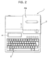
- the tape printer 1 includes a body frame 2 within which is installed a printing mechanism PM. At the front end of the body frame 2 is a keyboard 3. Behind the keyboard 3 is an LCD (liquid crystal display) 4 capable of displaying, for example, up to two lines of characters or symbols.
- LCD liquid crystal display
- the keyboard 3 includes character keys for entering alphanumerals and symbols, cursor keys for moving a cursor horizontally or vertically across the LCD, a return key for starting a new line of character strings, a text forming key for forming text, a finish key for indicating to the printer when text is complete, a mode set key for setting a line enhancement, a flush left key for making characters flush left as shown in Fig. 3, a centering key for centering characters as shown in Fig. 4, a flush right key for making characters flush right as shown in Fig. 5, a right-justification key for aligning characters on the printed lines along a right marginal line as shown in Fig. 6, a printing key for executing printing, and a power switch for turning the power ON and OFF.
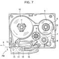
- a rectangular tape cassette CS is removably loaded in the body frame 2.
- the tape cassette CS contains a tape spool 6 around which is wound a printing tape 5 made of transparent film about 24 mm wide, a ribbon feed spool 8 around which an inking ribbon 7 is wound, a take-up spool 9 for taking up used inking ribbon 7, a feed spool 11 around which a double-sided adhesive tape 10 having the same width as the printing tape 5 is wound so its releasable sheet faces outward, and a bonding roller 12 for bonding the printing tape 5 to the double-sided adhesive tape 10.
- the roller 12 and spools 6, 8, 9, and 11 are all rotatably arranged within the cassette CS.
- a thermal head 13 is fixedly located at a position where the printing tape 5 and the inking ribbon 7 overlap each other.
- a platen roller 14 presses the printing tape 5 and the inking ribbon 7 against the thermal head 13.
- a feed roller 15 presses the printing tape 5 (which now contains characters) and double-sided adhesive tape 10 against the bonding roller 12.
- the platen roller 14 and the feed roller 15 are rotatably supported by a supporting member 16.
- the thermal head 13 contains 128 heating elements 13a arranged vertically to extend across the tape width, as shown in Fig. 8.
- the bonding roller 12 and the take-up spool 9 are rotated by a tape feed motor 24 in predetermined directions at speeds in synchronism with each other.
- the bonding roller 12, the take-up spool 9 and the tape feed motor 24 serve as means for uni-directionally feeding the printing tape 5.
- the heating elements 13a are selectively energized, causing a plurality of dot columns (dot strings) to be printed on the printing tape 5.
- the printing tape 5 with the double-sided adhesive tape 10 adhered thereto is fed in the direction of arrow A out of the body frame 2.
- the printing mechanism PM refer to Japanese Laid-Open Patent Publication No. 2-106555.
- the printing tape 5 is formed with a printing area PE.
- the printing area corresponds to the vertical length of the heating elements 13a and partially fills the printing tape 5 in the widthwise direction between a top line TL and a bottom line BL.
- Single-, double-, or, triple-printing of vertical lines as represented in Fig. 8 by characters "A", "D” and "F” respectively, can be printed within the printing area PE.
- Single-line printing i.e., filling the entire printing area PE with a single line
- creates large characters as represented by "A” in Fig. 8) formed by dot pattern data 120 dots high by 120 dots wide.
- Double-line printing i.e., dividing the printing area Pe into two equal-sized lines.
- creates medium-sized characters as represented by the two "D” characters in Fig. 8) formed by dot pattern data 48 dots high by 48 dots wide.
- Triple-line printing i.e., printing to fill the printing area PE with three equal-sized lines
- creates small characters as represented by the three "F” characters in Fig. 8) formed from dot pattern data 32 dots high by 32 dots wide.
- the line nearest the top line TL is called the first line
- the line nearest the bottom line BL is the third line
- the line between the first and third lines is the second line.
- a space equivalent to at least a row of four dots separates the uppermost printed area (for example, the upper tip of the single-line printed "A" character) and the top line TL, and a space equivalent to at least a row of four dots separates the lowermost printed area (for example, the base of the single-line printed "A" character) and the bottom line BL.
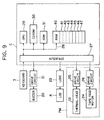
- the control system of the tape printer 1 is constructed as shown in Fig. 9.
- the control system includes a controller C which is connected via an interface 27 to the keyboard 3, a buzzer drive circuit 21 for driving a buzzer 20, an LCD (liquid crystal display) controller 23 which includes a display RAM for outputting display data to an LCD 4, a thermal head drive circuit 25 for driving the thermal head 13, and a feed motor drive circuit 26 for driving the feed motor 24.
- the thermal head drive circuit 25 and the feed motor drive circuit 26 are parts of the printing mechanism PM.
- the interface 27 of the controller C is connected by a bus 28 (e.g., a data bus) to a CPU (central processing unit) 29, a CGROM (character generating read-only memory) 30, a ROM 31, and a RAM (random access memory) 40, all contained within the controller C.
- the CGROM 30 stores dot pattern data required for printing each character in the large, medium, or small size, and another dot pattern data for outputing each character to the display RAM of the display controller 23 in association with coding data representative of the character.
- the ROM 31 stores a table indicating a relationship between the number of lines to be printed and size designating data representative of the size of character to be used for printing, with control programs which include such tape printing control programs as a mode setting control program for setting the specific line enhancements according to the present invention, a data input control program, a display control program, and a tape printing control program.
- the RAM 40 has a line buffer 41, a text memory 42, a line number memory 43, a flag memory 44, a maximum line length memory 45, a character position memory 46, and a character print buffer 47.
- the line buffer 41 temporarily stores both character code data (1 byte) representative of each character input from the keyboard 3 and character enhancement data (1 byte) such as size designating data which designate character size.
- the text memory 42 stores data transferred from the line buffer 41.
- the line number memory 43 temporarily stores a line number N to be printed on the tape.
- the flag memory 44 stores flag data for character lines, i.e. a flush left flag LF, a centering flag CF, and a flush right flag, which are set when flush left, centering, and flush right are set respectively.
- the flag data are stored corresponding to character lines set with line enhancement.
- the maximum line length memory 45 stores data regarding the line with the maximum length.
- the character position memory 46 stores, along with code data and size designating data, data of character positions for each character of enhanced lines.
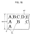
- the character buffer 47 stores character data of the plurality of characters for which dot pattern data was developed based on character position data, and other data, stored in the character position memory 46.
- line enhancement is set for triple-line printing with each line set to the right-justification. Tape thus printed will appear as shown in Fig. 6.
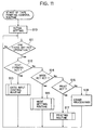
- Step S10 executes initial settings by clearing memories 41 through 47 and a line counter which designates the line to be printed.
- Operating the text forming key i.e., steps S11 and S12 are "yes" initiates data input routine S13 in which data input through operations of character keys are processed.
- step S20 causes, in step S21, the character code data for each character to be successively stored in the line buffer 41, and, in step S22, the characters to be displayed on the LCD 4.
- step S21 the character code data for each character to be successively stored in the line buffer 41
- step S22 the characters to be displayed on the LCD 4.
- a character string "ABCDEFGHIJKLMN" will appear on the LCD 4 at the first line.
- step S23 Pressing the return key (i.e., step S23 is "yes") stores the fact that the return key was pressed once in the line buffer 41, and, in step S25, moves the curser to the far left of the second line of the LCD 4. Pressing successively the character keys "A”, “B”, “C”, “D”, “E”, “F”, and “G” to print the second line on the tape causes steps S20 through S22 to repeat and the character string "ABCDEFG" to appear at the second line of the LCD 4. To further print the character string "ABC” on the third line, the return key is again pressed. That the return key was again pressed will be stored in the line buffer in step S24. It is noted that the return key has been pressed twice so far in this embodiment.
- a line number N to be printed on the tape is determined based on the number of times the return key was pressed by referring to the data stored in the line buffer 41.
- the resultant line number N is stored in the line number memory 43 in step S27. For example, if the return key was pressed once, the line number N would be two. In this embodiment the return key was pressed twice, so the line number N is three.
- step S28 the size of the characters at time of printing is set based on the line number N.
- step S29 the data in the line buffer 41 are transferred to the text memory 42.
- step S15 the mode setting routine for carrying out line enhancement.
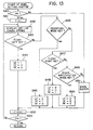
- the mode setting routine will be described while referring to Fig. 13.
- step S40 it is determined in step S40 whether the number of lines N is greater than two or not based on the data stored in the line number memory 43. If the number of lines is determined over two (i.e., step S40 is "yes"), the line counter is set to "1" to designate the first line as the object of the line enhancement. In step S42 the LCD 4 displays the character string on the first line. Operating the flush left mode key (i.e., step S43 is "yes") sets, in step S44, the flush left flag LF and resets both the centering mode flag CF and the flush right mode flag RF.
- step S43 sets, in step S46, the centering mode flag CF and resets both the flush left mode flag LF and the flush right mode flag RF.
- step S48 sets, in step S48, the flush right mode flag RF and resets both the flush left mode flag LF and the centering mode flag CF.
- step S50 Operating the right-justification mode key (i.e., steps S43, S45, and S47 are "no” and step S49 is "yes") resets, in step S50, the flush left mode flag LF, the centering mode flag CF, and the flush right mode flag RF. Because in this embodiment the right-justification mode is selected, the flush left mode flag LF, the centering mode flag CF, and the flush right mode flag RF are reset and flag data corresponding to each line are stored in the flag memory 44.
- step S53 whether or not the value of the line counter is over four is determined. If not (i.e., step S53 is "no") the routine returns to step S42. Because the line enhancement for the first line was just set, the value of the counter C is not greater than four so the routine returns to step S42 and line enhancement for the second and third lines are set. When line enhancements are set for all lines (i.e., step S53 is "yes") the routine returns to step S11.
- step S40 If, in step S40, the line number N is determined as one, or if a key other than the flush left mode key, the centering mode key, the flush right mode key and the right-justification mode key (i.e., steps S43, S45, S47, and S49 are "no") are pressed, the warning buzzer 20 goes off in step S51.
- step S17 Pressing the print key (i.e., steps S11 and S16 are “yes” and steps S12 and S14 are “no") initiates the printing routine in step S17.
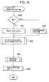
- the printing routine will be described while referring to Fig. 14.
- the printing routine starts, it is determined in step 60 whether or not the line number N is one (1) based on data in the line number memory 43. If the line number N equals one (i.e., step S60 is "yes"), dot pattern data for those characters to be printed on the line are developed in the print buffer 47 in step S62 based on character code data and size designating data stored in the text memory 42.
- step S63 a rearranging routine is executed in step S63 for developing dot pattern data in the print buffer based on the line enhancement set for each character for each line.
- the longest line is determined by comparing the number of characters in each line.
- step S70 the line number of the longest line is stored in the longest line memory 45. Because in this embodiment the longest line is the first line, "1" is stored in the longest line memory 45.
- the line counter is set to "1" in step S71.
- step S72 data for the first line are read from the text memory 42.
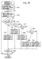
- step S73 the value in the line counter and the data stored in the longest line memory 45 are compared to determine whether or not the first line is the longest.
- step S73 is "yes"
- step S74 the position for each character of the first line is calculated for developing dot pattern data in the print buffer 47.
- step S74 the calculated results are stored, along with the size designating data and the character code data, in the character position memory 46 as character position data. Because in this embodiment the first line is the longest line, a standard position P n , for example, the origin 0 of the print buffer 47 as shown in Fig.
- step S82 one is added to the value of the line counter C.
- step S83 whether or not the valve of the line counter C is greater than four is determined. At this point in this embodiment, because the routine was completed for the first line only, the value of the line counter C is less than four, so the routine proceeds to step S72 where the data for the second line is read.
- step S73 whether or not the second line is the longest is determined by comparing the value in the counter C and the data in the longest line memory 45. In this embodiment the second line is not the longest line (i.e., step S73 is "no").
- the line enhancement for the second line is determined based on the flag data stored in the flag memory 44.
- the second line is set for right-justification (as are the first and third), (i.e., steps S75, S77, and S79 are "no").
- steps S75, S77, and S79 are "no"
- steps S75, S77, and S79 are "no"
- steps S75, S77, and S79 are "no"
- a standard position P n is calculated, based on the results of the above calculations, for each character of the longest character string to develop dot pattern data for the character buffer 47.
- step S81 the calculated results are stored, along with the size designating data and character code data, in the character position memory 46 as character position data.
- the routine then proceeds to step S82.
- Steps S83 and S72 through S81 are executed for the third line as they were the second line.
- step S83 the value of the counter C will be greater than that of the line number N (i.e., step S83 is "yes") and the routine returns to step S62. If any line had been set with the flush left mode line enhancement (i.e., step S75 is "yes") step 76 of the routine would be executed. Similarly, if any line had been set with either the centering or flush right mode line enhancement (i.e., step S78 or S80 respectively is "yes") step S78 and S80 respectively would be executed.
- step S62 the character print buffer 47 develops the dot pattern data for each character as shown in Fig. 15 based on the character position data for each character of each line, the size designating data, and the character code data stored in the character position memory 46.
- step S64 double-sided adhesive tape 10 is adhered to the printing tape 5.
- step S65 a predetermined amount of tape is fed and cut and the routine returns to step S11.
- line enhancement By operating the flush left mode key, the centering mode key, the flush right mode key, or the right-justification mode key, line enhancement can be easily set for each character print line, which increases flexibility in laying out text to be printed, aesthetic quality of printed lines, and practicality of the tape printer.
Applications Claiming Priority (2)
| Application Number | Priority Date | Filing Date | Title |
|---|---|---|---|
| JP4018508A JP2556233B2 (ja) | 1992-01-07 | 1992-01-07 | テープ印字装置 |
| JP18508/92 | 1992-01-07 |
Publications (2)
| Publication Number | Publication Date |
|---|---|
| EP0551995A1 true EP0551995A1 (de) | 1993-07-21 |
| EP0551995B1 EP0551995B1 (de) | 1995-12-06 |
Family
ID=11973571
Family Applications (1)
| Application Number | Title | Priority Date | Filing Date |
|---|---|---|---|
| EP93300104A Expired - Lifetime EP0551995B1 (de) | 1992-01-07 | 1993-01-07 | Banddrucker mit Linienverstärkungsfähigkeit |
Country Status (4)
| Country | Link |
|---|---|
| US (1) | US5403101A (de) |
| EP (1) | EP0551995B1 (de) |
| JP (1) | JP2556233B2 (de) |
| DE (1) | DE69300915T2 (de) |
Cited By (6)
| Publication number | Priority date | Publication date | Assignee | Title |
|---|---|---|---|---|
| EP0639813A2 (de) * | 1993-08-18 | 1995-02-22 | Brother Kogyo Kabushiki Kaisha | Druckvorrichtung und Verfahren |
| EP0651347A2 (de) * | 1993-11-02 | 1995-05-03 | King Jim Co., Ltd. | Layout-Anzeigegerät für Streifendrucker zur Anzeige von Mehrzeilenzeichen mit hoher Geschwindigkeit |
| EP0652109A2 (de) * | 1993-11-09 | 1995-05-10 | King Jim Co., Ltd. | Gerät und Verfahren zum Bedrucken eines Streifens mit Buchstaben |
| EP0695643A1 (de) * | 1993-12-22 | 1996-02-07 | Seiko Epson Corporation | Streifendrucker |
| EP0885734A1 (de) * | 1994-01-18 | 1998-12-23 | Esselte N.V. | Kassette |
| EP1167049A1 (de) * | 1994-11-29 | 2002-01-02 | King Jim Co., Ltd. | Banddruckvorrichtung |
Families Citing this family (19)
| Publication number | Priority date | Publication date | Assignee | Title |
|---|---|---|---|---|
| CA2107759A1 (en) * | 1992-10-06 | 1994-04-07 | Masahiko Nunokawa | Tape printing device |
| US5836061A (en) * | 1997-07-12 | 1998-11-17 | Honda Giken Kogyo Kabushiki Kaisha | Cable end anchoring nipple and methods of constructing and utilizing same |
| US6092947A (en) * | 1992-10-06 | 2000-07-25 | Seiko Epson Corporation & King Jim Co., Ltd. | Tape printing device |
| GB9300715D0 (en) * | 1993-01-14 | 1993-03-03 | Esselte Dymo Nv | Label printing apparatus |
| WO1995017309A1 (fr) * | 1993-12-22 | 1995-06-29 | Seiko Epson Corporation | Imprimante de bandes |
| JP3349577B2 (ja) | 1993-12-30 | 2002-11-25 | セイコーエプソン株式会社 | 印字装置 |
| JPH0911545A (ja) * | 1995-03-31 | 1997-01-14 | Seiko Epson Corp | 空白設定機能付きテープ印刷装置 |
| JPH09237078A (ja) | 1995-12-28 | 1997-09-09 | Seiko Epson Corp | 画像形成装置における外字作成方法 |
| US6226094B1 (en) * | 1996-01-05 | 2001-05-01 | King Jim Co., Ltd. | Apparatus and method for processing character information |
| JP3478106B2 (ja) | 1997-12-19 | 2003-12-15 | セイコーエプソン株式会社 | キャラクタ画像割付装置 |
| JP2004130656A (ja) * | 2002-10-10 | 2004-04-30 | Brother Ind Ltd | 印刷装置、及びプログラム |
| JP4534502B2 (ja) * | 2004-01-30 | 2010-09-01 | ブラザー工業株式会社 | テープ印字装置 |
| EP1809482A2 (de) * | 2004-03-10 | 2007-07-25 | Kroy, Llc | Banddruckvorrichtung und druckverfahren |
| JP4546164B2 (ja) * | 2004-06-17 | 2010-09-15 | セイコーエプソン株式会社 | 文字情報処理装置、文字情報処理装置の情報処理方法、プログラムおよび記憶媒体 |
| JP4706467B2 (ja) * | 2005-03-31 | 2011-06-22 | ブラザー工業株式会社 | 印刷データ編集装置、印刷データ編集プログラム及び印刷データ編集プログラムを記録した記録媒体 |
| US7410311B2 (en) * | 2005-03-31 | 2008-08-12 | Brother Kogyo Kabushiki Kaisha | Print data editing device, print data editing program and computer readable recording medium |
| JP2007245663A (ja) * | 2006-03-17 | 2007-09-27 | Casio Comput Co Ltd | 印字装置 |
| JP5360488B2 (ja) * | 2009-09-30 | 2013-12-04 | カシオ計算機株式会社 | 印字装置、印字物を作成する作成方法及びコンピュータ読み取り可能な記憶媒体 |
| US8471878B2 (en) * | 2011-02-24 | 2013-06-25 | Cobra Systems, Inc. | Sign maker templates for producing centered labels and methods of use |
Citations (2)
| Publication number | Priority date | Publication date | Assignee | Title |
|---|---|---|---|---|
| US4661001A (en) * | 1984-08-08 | 1987-04-28 | Tokyo Electric Co., Ltd. | Label printer with test pattern for price and bar codes |
| US4836712A (en) * | 1984-12-29 | 1989-06-06 | Casio Computer Co., Ltd. | Electronic word processing with sequential character attribute compounding |
Family Cites Families (21)
| Publication number | Priority date | Publication date | Assignee | Title |
|---|---|---|---|---|
| JPS5829679A (ja) * | 1981-08-17 | 1983-02-21 | Tsutomu Tamura | ミニプリンタ− |
| JPS58212972A (ja) * | 1982-06-04 | 1983-12-10 | Sharp Corp | メモ印字装置 |
| US4573138A (en) * | 1982-11-09 | 1986-02-25 | International Business Machines Corp. | Justifying with printer level data stream which accommodates footers and headers |
| JPS6027583A (ja) * | 1983-07-26 | 1985-02-12 | Canon Inc | マイクロスペ−シングの管理方式 |
| JPS60234856A (ja) * | 1984-05-09 | 1985-11-21 | Canon Inc | 記録装置 |
| US4783760A (en) * | 1985-06-03 | 1988-11-08 | Honeywell Bull Inc. | Word processing text justification method |
| JPS62128774A (ja) * | 1985-11-29 | 1987-06-11 | Teraoka Seiko Co Ltd | プリンタ |
| JPS6335431A (ja) * | 1986-07-29 | 1988-02-16 | Furukawa Electric Co Ltd:The | 光フアイバ母材の製造方法 |
| JPH0677253B2 (ja) * | 1987-04-08 | 1994-09-28 | 松下電送株式会社 | 宛名印刷装置 |
| JPH01113258A (ja) * | 1987-10-27 | 1989-05-01 | Canon Inc | 印刷装置 |
| US4976558A (en) * | 1987-11-19 | 1990-12-11 | Brother Kogyo Kabushiki Kaisha | Device for feeding recording medium in the longitudinal recording direction |
| JPH01229673A (ja) * | 1988-03-11 | 1989-09-13 | Toshiba Corp | 英殴文印刷制御方式 |
| JP2564210Y2 (ja) * | 1988-06-08 | 1998-03-04 | ブラザー工業株式会社 | ラベル印字装置 |
| JP2535059B2 (ja) * | 1988-08-09 | 1996-09-18 | 株式会社ピーエフユー | 文字処理装置 |
| JPH02176853A (ja) * | 1988-12-27 | 1990-07-10 | Sharp Corp | 文字処理装置 |
| JPH078585B2 (ja) * | 1989-04-14 | 1995-02-01 | シャープ株式会社 | 手走査式プリンタ |
| JPH03156668A (ja) * | 1989-11-15 | 1991-07-04 | Toshiba Corp | 文書作成装置 |
| JP3166206B2 (ja) * | 1990-08-29 | 2001-05-14 | セイコーエプソン株式会社 | テーププリンタ及びその制御方法 |
| EP0475625B1 (de) * | 1990-08-31 | 1996-05-22 | New Oji Paper Co., Ltd. | Drucker mit einem Bogenschneider |
| JP2643569B2 (ja) * | 1990-09-12 | 1997-08-20 | ブラザー工業株式会社 | テープ印字装置 |
| JP2536322B2 (ja) * | 1991-03-28 | 1996-09-18 | ブラザー工業株式会社 | テ―プ印字装置 |
-
1992
- 1992-01-07 JP JP4018508A patent/JP2556233B2/ja not_active Expired - Fee Related
-
1993
- 1993-01-07 US US08/001,755 patent/US5403101A/en not_active Expired - Lifetime
- 1993-01-07 EP EP93300104A patent/EP0551995B1/de not_active Expired - Lifetime
- 1993-01-07 DE DE69300915T patent/DE69300915T2/de not_active Expired - Lifetime
Patent Citations (2)
| Publication number | Priority date | Publication date | Assignee | Title |
|---|---|---|---|---|
| US4661001A (en) * | 1984-08-08 | 1987-04-28 | Tokyo Electric Co., Ltd. | Label printer with test pattern for price and bar codes |
| US4836712A (en) * | 1984-12-29 | 1989-06-06 | Casio Computer Co., Ltd. | Electronic word processing with sequential character attribute compounding |
Cited By (14)
| Publication number | Priority date | Publication date | Assignee | Title |
|---|---|---|---|---|
| US5579041A (en) * | 1993-08-18 | 1996-11-26 | Brother Kogyo Kabushiki Kaisha | Printing device bordering function and a method thereof |
| EP0639813A3 (de) * | 1993-08-18 | 1995-09-27 | Brother Ind Ltd | Druckvorrichtung und Verfahren. |
| EP0639813A2 (de) * | 1993-08-18 | 1995-02-22 | Brother Kogyo Kabushiki Kaisha | Druckvorrichtung und Verfahren |
| EP0651347A2 (de) * | 1993-11-02 | 1995-05-03 | King Jim Co., Ltd. | Layout-Anzeigegerät für Streifendrucker zur Anzeige von Mehrzeilenzeichen mit hoher Geschwindigkeit |
| EP0651347A3 (de) * | 1993-11-02 | 1997-04-16 | King Jim Co Ltd | Layout-Anzeigegerät für Streifendrucker zur Anzeige von Mehrzeilenzeichen mit hoher Geschwindigkeit. |
| EP0652109A3 (de) * | 1993-11-09 | 1997-12-17 | King Jim Co., Ltd. | Gerät und Verfahren zum Bedrucken eines Streifens mit Buchstaben |
| EP0652109A2 (de) * | 1993-11-09 | 1995-05-10 | King Jim Co., Ltd. | Gerät und Verfahren zum Bedrucken eines Streifens mit Buchstaben |
| EP0695643A4 (de) * | 1993-12-22 | 1996-02-14 | ||
| EP0695643A1 (de) * | 1993-12-22 | 1996-02-07 | Seiko Epson Corporation | Streifendrucker |
| US5810486A (en) * | 1993-12-22 | 1998-09-22 | Seiko Epson Corporation | Tape printing apparatus |
| US6168323B1 (en) | 1993-12-22 | 2001-01-02 | Seiko Epson Corporation | Tape printing apparatus |
| KR100343294B1 (ko) * | 1993-12-22 | 2002-10-31 | 킹 짐(주) | 테이프인쇄장치 |
| EP0885734A1 (de) * | 1994-01-18 | 1998-12-23 | Esselte N.V. | Kassette |
| EP1167049A1 (de) * | 1994-11-29 | 2002-01-02 | King Jim Co., Ltd. | Banddruckvorrichtung |
Also Published As
| Publication number | Publication date |
|---|---|
| JPH05185663A (ja) | 1993-07-27 |
| EP0551995B1 (de) | 1995-12-06 |
| US5403101A (en) | 1995-04-04 |
| DE69300915D1 (de) | 1996-01-18 |
| JP2556233B2 (ja) | 1996-11-20 |
| DE69300915T2 (de) | 1996-06-05 |
Similar Documents
| Publication | Publication Date | Title |
|---|---|---|
| EP0551995B1 (de) | Banddrucker mit Linienverstärkungsfähigkeit | |
| US5860752A (en) | Tape printing device | |
| US5230572A (en) | Tape printer having spacing function | |
| US5813779A (en) | Printing apparatus having user keys | |
| EP0577247B1 (de) | Streifendrucker | |
| EP0506461B2 (de) | Banddruckvorrichtung zum Drucken einer Mehrzahl von benachbarten Drucklinien über die Breite des Bandes | |
| US5395173A (en) | Bar code and text printer capable of displaying bar code location | |
| EP0577250B1 (de) | Streifendrucker | |
| JPH05185653A (ja) | テープ印字装置 | |
| US6120200A (en) | Tape printing device | |
| US6338583B1 (en) | Printing apparatus | |
| EP0573262B1 (de) | Textverarbeitungsgerät | |
| EP0606768A2 (de) | Prozessor für Punktmuster-Ausrichtungsdaten in einer Textverarbeitungsvorrichtung | |
| JPH05185654A (ja) | テープ印字装置 | |
| JP3292393B2 (ja) | 文書処理装置 | |
| US5647676A (en) | Document processing device having ruling function | |
| JP3139514B2 (ja) | テープ印字装置 | |
| JP3208978B2 (ja) | テープ印字装置 | |
| JPH08314924A (ja) | 文書処理装置 | |
| JPH06203028A (ja) | 文書処理装置 | |
| JPH11212960A (ja) | 文書処理装置 | |
| JP2508933C (de) | ||
| JP2546194C (de) | ||
| JPH05177900A (ja) | 印字装置 |
Legal Events
| Date | Code | Title | Description |
|---|---|---|---|
| PUAI | Public reference made under article 153(3) epc to a published international application that has entered the european phase |
Free format text: ORIGINAL CODE: 0009012 |
|
| AK | Designated contracting states |
Kind code of ref document: A1 Designated state(s): BE DE FR GB |
|
| 17P | Request for examination filed |
Effective date: 19930823 |
|
| 17Q | First examination report despatched |
Effective date: 19950116 |
|
| GRAA | (expected) grant |
Free format text: ORIGINAL CODE: 0009210 |
|
| AK | Designated contracting states |
Kind code of ref document: B1 Designated state(s): BE DE FR GB |
|
| ET | Fr: translation filed | ||
| REF | Corresponds to: |
Ref document number: 69300915 Country of ref document: DE Date of ref document: 19960118 |
|
| PLBE | No opposition filed within time limit |
Free format text: ORIGINAL CODE: 0009261 |
|
| STAA | Information on the status of an ep patent application or granted ep patent |
Free format text: STATUS: NO OPPOSITION FILED WITHIN TIME LIMIT |
|
| 26N | No opposition filed | ||
| REG | Reference to a national code |
Ref country code: GB Ref legal event code: IF02 |
|
| PGFP | Annual fee paid to national office [announced via postgrant information from national office to epo] |
Ref country code: GB Payment date: 20101215 Year of fee payment: 19 |
|
| PGFP | Annual fee paid to national office [announced via postgrant information from national office to epo] |
Ref country code: FR Payment date: 20120111 Year of fee payment: 20 |
|
| PGFP | Annual fee paid to national office [announced via postgrant information from national office to epo] |
Ref country code: DE Payment date: 20120131 Year of fee payment: 20 |
|
| PGFP | Annual fee paid to national office [announced via postgrant information from national office to epo] |
Ref country code: BE Payment date: 20120222 Year of fee payment: 20 |
|
| REG | Reference to a national code |
Ref country code: DE Ref legal event code: R071 Ref document number: 69300915 Country of ref document: DE |
|
| REG | Reference to a national code |
Ref country code: GB Ref legal event code: PE20 Expiry date: 20130106 |
|
| BE20 | Be: patent expired |
Owner name: *BROTHER KOGYO K.K. Effective date: 20130107 |
|
| PG25 | Lapsed in a contracting state [announced via postgrant information from national office to epo] |
Ref country code: GB Free format text: LAPSE BECAUSE OF EXPIRATION OF PROTECTION Effective date: 20130106 Ref country code: DE Free format text: LAPSE BECAUSE OF EXPIRATION OF PROTECTION Effective date: 20130108 |