EP0546789A2 - Procédé et système pour estimer le point neutre d'un volant de direction - Google Patents
Procédé et système pour estimer le point neutre d'un volant de direction Download PDFInfo
- Publication number
- EP0546789A2 EP0546789A2 EP92311149A EP92311149A EP0546789A2 EP 0546789 A2 EP0546789 A2 EP 0546789A2 EP 92311149 A EP92311149 A EP 92311149A EP 92311149 A EP92311149 A EP 92311149A EP 0546789 A2 EP0546789 A2 EP 0546789A2
- Authority
- EP
- European Patent Office
- Prior art keywords
- wheel angle
- wheel
- steering
- specified
- determining
- Prior art date
- Legal status (The legal status is an assumption and is not a legal conclusion. Google has not performed a legal analysis and makes no representation as to the accuracy of the status listed.)
- Granted
Links
Images

Classifications
-
- B—PERFORMING OPERATIONS; TRANSPORTING
- B62—LAND VEHICLES FOR TRAVELLING OTHERWISE THAN ON RAILS
- B62D—MOTOR VEHICLES; TRAILERS
- B62D15/00—Steering not otherwise provided for
- B62D15/02—Steering position indicators ; Steering position determination; Steering aids
-
- G—PHYSICS
- G01—MEASURING; TESTING
- G01D—MEASURING NOT SPECIALLY ADAPTED FOR A SPECIFIC VARIABLE; ARRANGEMENTS FOR MEASURING TWO OR MORE VARIABLES NOT COVERED IN A SINGLE OTHER SUBCLASS; TARIFF METERING APPARATUS; MEASURING OR TESTING NOT OTHERWISE PROVIDED FOR
- G01D1/00—Measuring arrangements giving results other than momentary value of variable, of general application
- G01D1/14—Measuring arrangements giving results other than momentary value of variable, of general application giving a distribution function of a value, i.e. number of times the value comes within specified ranges of amplitude
-
- B—PERFORMING OPERATIONS; TRANSPORTING
- B62—LAND VEHICLES FOR TRAVELLING OTHERWISE THAN ON RAILS
- B62D—MOTOR VEHICLES; TRAILERS
- B62D15/00—Steering not otherwise provided for
- B62D15/02—Steering position indicators ; Steering position determination; Steering aids
- B62D15/021—Determination of steering angle
- B62D15/0245—Means or methods for determination of the central position of the steering system, e.g. straight ahead position
Definitions
- the present invention relates to a method and system for estimating the neutral point of the steering wheel of a vehicle while the vehicle is traveling.
- the steering wheel i.e., the steering shaft
- the steering wheel is generally equipped with a wheel angle sensor.
- This wheel angle sensor functions to detect a wheel angle when the steering wheel is steered, for allowing a front-wheel steering angle to be determined from the detected wheel angle.
- the steering angle of front wheels provides an important control factor for implementing, for example, rear-wheel steering control or the trace control and the like of a traction control system; therefore, the wheel angle sensor must be capable of detecting the steering angle of front wheels with high accuracy.
- the wheel angle sensor is designed to detect a wheel angle when the steering wheel is steered to the right or left from its neutral point, i.e., the front-wheel steering angle. For this reason, a vehicle must be traveling straight ahead whenever the neutral point of the steering wheel is detected through the wheel angle sensor.
- Japanese Utility Model Applications Laid-Open H2-85675 discloses a technology for correcting the neutral point of a wheel angle sensor output on the basis of the output of the wheel angle sensor obtained when the pressure difference between the right and left pressure chambers of a power steering unit is zero.
- the present invention is based on the aforesaid circumstances, and its object is to provide a method and system for estimating the neutral point of a steering wheel, which method is useful for permitting correction of a sensor signal of a wheel angle sensor or implementation of a highly accurate detection of a front-wheel steering angle.
- a method and system for estimating the neutral position of a steering wheel comprises a straight-ahead travel judgment step and means of judging that a vehicle is in a straight ahead travel condition, and a neutral point estimating step of estimating the neutral point of an output of a wheel angle sensor on the basis of an output of the wheel angle sensor obtained under a condition where the aforesaid straight-ahead travel condition of the vehicle is recognized.
- the aforesaid straight-ahead travel judgement step and means comprise a first detection step and means of detecting that the aforesaid straight-ahead travel condition has lasted for a specified time, and a second detection step and means of detecting an output of the aforesaid wheel angle sensor at intervals of a specified cycle which is shorter than the aforesaid specified time, until the lapse of the aforesaid specified time is detected.
- the aforesaid neutral estimating step and means comprise a distribution calculating step and means of determining a detection frequency distribution which corresponds to a series of wheel angles detected in the aforesaid second detection step, and a neutral point deciding step and means of determining the neutral point of a wheel angle sensor output from the aforesaid detection frequency distribution.
- a series of detected wheel angles are obtained from the outputs of the wheel angle sensor when the straight-ahead travel condition of a vehicle lasts for a specified time, and the neutral point of the wheel angle sensor is output.
- the neutral point of the steering wheel is estimated from the detection frequency distribution corresponding to that series of detected wheel angles; therefore, it is possible to accurately determine the neutral point of the steering wheel even if the straight-ahead travel condition of a vehicle can be determined only with a certain degree of accuracy.
- the detection frequency distribution is determined based on the wheel angle detection frequencies in a plurality of small wheel angle regions obtained by dividing a specified wheel angle region.
- the neutral point deciding step and means include a weighted mean step and means of calculating the weighted mean value of detected wheel angles, as the neutral point of the wheel angle sensor output, from the detection frequency distribution, for thereby making it possible to accurately determine the neutral point of the steering wheel.
- the straight-ahead travel condition can be easily judged by judging the straight-ahead travel condition of a vehicle on when the working pressure of a hydraulic power steering system for assisting the operating physical force of the steering wheel is a specified pressure or less.
- accurate judgment of the straight-ahead travel condition can be performed by rendering the judgment of the straight-ahead travel condition valid only when it is determined that the car speed is a specified car speed or higher or when no steering speed of a specified value or higher is generated. This permits accurate determination of the neutral point of a steering wheel.
- the neutral point it is made possible to accurately estimate the neutral point with a reduced memory capacity by providing a plurality of arrays for accumulating the values, which indicate wheel angle detection frequencies in a plurality of small wheel angle regions, by determining the detection frequency distribution by adding one to an accumulated value which corresponds to a detected wheel angle of the plurality of arrays each time a wheel angle sensor output is detected, and subtracting one from the accumulated values of all the arrays when there is an array which has a value exceeding a maximum allowable value.
- FIG. 1 a hydraulic power steering system of a vehicle is schematically shown.
- This hydraulic power steering system is equipped with a power cylinder 1, and both ends of a piston rod 2 in the power cylinder 1 are arranged to be linked to the right and left front wheels although they are not illustrated.
- piston rod 2 and a steering wheel 3, i.e., its steering shaft 4 are interconnected via a rack and a pinion although they are not illustrated. Accordingly, when the steering wheel 3 is steered to the right or left, the piston rod 2 is mechanically driven via the rack and pinion, thus making it possible to drive the front wheels to the right or left.
- the power cylinder 1 incorporates a pair of pressure chambers (not shown) formed on both sides of the piston by the piston made integral with the piston rod 2 and the circumferential wall of the power cylinder. These pressure chambers are connected to a control valve 7 of the power steering system via hydraulic lines 5 and 6.
- a hydraulic supply line 8 extends from the control valve 7 and the hydraulic supply line 8 is connected to a hydraulic reservoir 11 via a hydraulic pump 10 driven by an engine 9.
- a return line 12 also extends from the control valve 7, and the return line 12 is directly connected to the hydraulic reservoir 11.
- the aforementioned control valve 7 When the steering wheel 3 is steered, the aforementioned control valve 7 is operated to supply oil pressure to a pressure chamber, which corresponds to that steering direction for actuating the piston rod 2 by the hydraulic pressure, and thus adds to the steering power of the steering wheel 3.
- the control valve 7 When the steering wheel 3 is not steered, the control valve 7 is in the neutral position, and the hydraulic pressure supplied from the hydraulic pump 10 is immediately returned to the hydraulic reservoir 11 from the control valve 7 via the return line 12; therefore, no pressure difference develops between the right and left pressure chambers of the power cylinder 1.
- a wheel angle sensor 13 is mounted on the steering shaft 4, and the wheel angle sensor 13 is electrically connected to a controller, for instance, a one-chip microcomputer 14.
- the wheel angle sensor 13 is a digital type sensor using a photo interrupter; therefore, when the steering wheel 3 is steered, the wheel angle sensor 13 detects the wheel angle of the steering wheel 3 with a resolution of 1° and supplies the wheel angle to the microcomputer 14.
- the microcomputer 14 incorporates a program for estimating, that is, computing, the neutral point of the steering wheel 3.
- a program for estimating that is, computing, the neutral point of the steering wheel 3.
- electrically connected to the microcomputer 14 are pressure sensors 15 and 16 for detecting the pressures in the right and left pressure chambers of the power steering 1, and a car speed sensor 17 for detecting the speed of the vehicle, in addition to the wheel angle sensor 13.
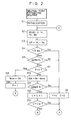
- the estimating routine is designed to be repeatedly implemented at intervals of 5-msec., for example.
- initialization is performed.
- the values of, for example, a counter C, a flag F, and a plurality of arrays D [ ⁇ H(n)] for storing wheel angle detection frequencies to be discussed later are all reset to 0.
- each array consists of a memory area including 8 bits, for example.
- Each array is related to a corresponding one of a plurality of small wheel angle ranges or regions, which are obtained by dividing a specified wheel angle range or region wherein the wheel angle changes, for instance, from ⁇ H(-n1) to ⁇ H(n1), and each array is designed to store a detection frequency of wheel angles that fall into the small wheel angle range concerned.
- the wheel angle ⁇ H detected as a neutral point (wheel neutral angle) "n" of the steering wheel 3 takes a value which falls into a range from -10° to 10°; therefore, the wheel angles ⁇ (-n1) and ⁇ (n1) which correspond to the small wheel angle ranges on both ends of the specified wheel angle range, i.e., the minimum wheel neutral angle - n1 and the maximum wheel neutral angle n1, are set to -10° and 10°, respectively.
- the angle width of the small wheel angle range is set to 1° which is equivalent to the resolution of the wheel angle sensor 13. Accordingly, the specified wheel angle range from -10° to 10° is divided into (2n1 + 1) ranges, namely, 21 small wheel angle ranges.
- step S2 a car speed V, pressures PL and PR of the pressure chambers, and a wheel angle ⁇ H supplied from the aforesaid sensors are read into the microcomputer 14. Then in a step S3, a power steering pressure ⁇ P of the power cylinder 1 is calculated.
- the power steering pressure ⁇ P of the power cylinder 1 is calculated from a difference between the pressure PL and the pressure PR detected through a pair of pressure sensors 15 and 16.
- the system judges in sequence whether the car speed V has exceeded a specified car speed V60 (e.g., 60km/h) and the absolute value of the power steering pressure ⁇ P, i.e.,
- step S6 If the judgment result of either the step S4 or S5 is negative (NO), then the system executes a step S6 and goes back to the step S2 to repeat the step S2 and the subsequent steps. In the step S6, the values of the counter C and the flag F are reset to 0.
- step S7 determines whether the flag F is set to 0.
- the system proceeds to a step S8, stores the wheel angle ⁇ H at that time as a reference wheel angle ⁇ H(B), and the system sets 1 in the flag F in a step S9.
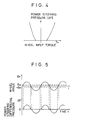
- the condition where the judgment results of both steps S4 and S5 become positive, indicates that the vehicle is traveling at a medium or higher speed, the steering wheel 3 is not steered, that is, the absolute value of a wheel input torque is a specified value or less, and the power steering pressure ⁇ P has not virtually risen in the power cylinder 1 as shown in FIG. 4.
- this condition indicates that a vehicle is traveling straight ahead.
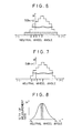
- the power steering pressure ⁇ P that appears in the power cylinder 1 changes as shown in FIG. 5.
- the power steering pressure ⁇ P does not virtually rise until the steering wheel 3 is steered by a specified wheel angle
- the reference wheel angle ⁇ H(B) obtained by implementing the step S8 comes to temporarily indicate the neutral point of the steering wheel 3 when the vehicle is traveling straight ahead.
- step S9 the steps following the step S2 are repeated. If the system reaches the step S7 with the judgment results of the steps S4 and S5 being both positive, then the judgment result of the step S7 becomes negative, which causes the next step S10 to be carried out.
- the system judges whether the absolute value
- of the wheel angle deviation ⁇ ⁇ H is a specified angle ⁇ 1 or less (in the case of this embodiment, the specified angle is set, for example, to ⁇ 1 1°, in consideration of the detection resolution of the wheel angle sensor 13). If the judgment result is negative, the system goes through the aforesaid step S6 and then repeats the step S2 and the subsequent steps.
- step S11 if the judgment result of the step S11 is positive, then the value of the counter C is incremented by 1 in a step S12, and it is judged in the next step S13 whether the value of the counter C has reached a specified number C20 (e.g., 20).
- a specified number C20 e.g. 20
- step S13 If the judgment in the step S13 is carried out immediately after the judgment result of the step S7 becomes positive, then the judgment result will be negative; therefore, the system goes back from the step to the step S2 to repeat the step S2 and the subsequent steps.
- step S14 indicates a straight-ahead travel condition of a vehicle, wherein the car speed V is V60 or more, the power steering pressure ⁇ P of the power cylinder 1 is the specified pressure P1 or less, and the wheel angular velocity is 10°/sec. or less as is obvious from the judgment results of the steps S4, S5, S11, and S13 as previously mentioned.
- step S14 the counter C and the flag F are both reset to 0.
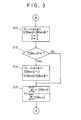
- the system judges whether one or more stored values of the 21 memory areas (arrays), which indicate the wheel angle detection frequencies D [ ⁇ H(n)] in the 21 small wheel angle ranges, have reached a maximum permissible value M.
- step S15 If the judgment result of the step S15 is negative, then the system proceeds to a step S17, and bypasses a step S16.
- step S17 the system goes back to the step S2 of FIG. 2 to repeat the steps following S2.
- the value of the array D [ ⁇ H(n)] which corresponds to the wheel angle ⁇ H(n) detected as the wheel neutral angle "n" at that point, is increased in sequence. Accordingly, the value of the array D [ ⁇ H(n)] represents the detection frequency of the wheel neutral angle "n;” therefore, the frequency distribution, which corresponds to the wheel neutral angle "n,” can be obtained as shown in FIG. 6.
- step S16 is executed before the step S17 is implemented.
- the value of each array D [ ⁇ H(n)] is decremented by 1 provided that the value of the array D [ ⁇ H(n)] is larger than 0 within a range of -n1 ⁇ n ⁇ n1.
- the weighted mean value Y calculated in the aforesaid step S17 accurately indicates the neutral point of the steering wheel 3 and the neutral point of the output of the wheel angle sensor 13 at which the vehicle is kept in the straight-ahead travel condition.
- the weighted mean value Y i.e., the neutral point of the steering wheel 3, is supplied from the microcomputer 14 to a 4-wheel steering system (4WS system) 18 or a traction control system (TCL system) 19 as shown in FIG. 1 each time the neutral point is calculated through the estimating routine, and the neutral point is used in these systems to correct the wheel angle ⁇ H detected through the wheel angle sensor 13.
- 4WS system 18 or the TCL system 19 it is possible to carry out rear-wheel steering control or trace control using the accurate wheel angle ⁇ H, thereby allowing optimum control to be performed.
- the present invention is not limited to the embodiments described above but various modifications thereof may be made.
- the values of V60, P1, ⁇ 1, and M are just examples and therefore they are not limited to those values.
- the neutral point of the steering wheel estimated from the weighted mean value Y can be of course applied to diverse control systems, which are based on wheel angles, other than the 4WS system and the TLC system.
- the wheel angle of the maximum detection frequency may be decided as the neutral point of the steering wheel without calculating the weighted mean value Y.
Landscapes
- Engineering & Computer Science (AREA)
- Chemical & Material Sciences (AREA)
- Combustion & Propulsion (AREA)
- Transportation (AREA)
- Mechanical Engineering (AREA)
- Physics & Mathematics (AREA)
- General Physics & Mathematics (AREA)
- Steering Control In Accordance With Driving Conditions (AREA)
- Force Measurement Appropriate To Specific Purposes (AREA)
- Indicating Or Recording The Presence, Absence, Or Direction Of Movement (AREA)
- Length Measuring Devices With Unspecified Measuring Means (AREA)
- Mechanical Control Devices (AREA)
Applications Claiming Priority (2)
| Application Number | Priority Date | Filing Date | Title |
|---|---|---|---|
| JP325888/91 | 1991-12-10 | ||
| JP3325888A JPH05162652A (ja) | 1991-12-10 | 1991-12-10 | ステアリングハンドルの中立点推定方法 |
Publications (3)
| Publication Number | Publication Date |
|---|---|
| EP0546789A2 true EP0546789A2 (fr) | 1993-06-16 |
| EP0546789A3 EP0546789A3 (fr) | 1994-04-06 |
| EP0546789B1 EP0546789B1 (fr) | 1997-02-19 |
Family
ID=18181722
Family Applications (1)
| Application Number | Title | Priority Date | Filing Date |
|---|---|---|---|
| EP92311149A Expired - Lifetime EP0546789B1 (fr) | 1991-12-10 | 1992-12-08 | Procédé et système pour estimer le point neutre d'un volant de direction |
Country Status (5)
| Country | Link |
|---|---|
| US (1) | US5311432A (fr) |
| EP (1) | EP0546789B1 (fr) |
| JP (1) | JPH05162652A (fr) |
| KR (1) | KR960005854B1 (fr) |
| DE (1) | DE69217540T2 (fr) |
Cited By (11)
| Publication number | Priority date | Publication date | Assignee | Title |
|---|---|---|---|---|
| EP0747282A1 (fr) * | 1995-06-09 | 1996-12-11 | Ford Motor Company Limited | Méthode pour déterminer la position centrale d'un système de direction de véhicule |
| WO2000066416A1 (fr) * | 1999-04-30 | 2000-11-09 | Daimlerchrysler Ag | Procede d'egalisation d'un signal d'angle au volant |
| EP0978441A3 (fr) * | 1998-08-03 | 2002-11-20 | Koyo Seiko Co., Ltd. | Dispositif détecteur du point milieu de l'angle de rotation du volant et direction assistée |
| EP0962379A3 (fr) * | 1998-06-01 | 2002-11-20 | Ford Global Technologies, Inc. | Méthode et dispositif pour déterminer la position centrée d'un système de direction |
| EP1262850A2 (fr) * | 2001-05-25 | 2002-12-04 | The Raymond Corporation | Dispositif de commande de la direction de véhicules de manutention de charges |
| US6816799B2 (en) | 2002-08-05 | 2004-11-09 | Robert Bosch Corporation | Vehicle operating parameter determination system and method |
| FR2876973A1 (fr) * | 2004-10-26 | 2006-04-28 | Koyo Steering Europ K S E Soc | Procede de correction des mesures du couple exerce sur un volant de conduite d'une direction assistee electrique de vehicule automobile |
| EP1642806A3 (fr) * | 2004-10-01 | 2006-05-31 | Toyota Jidosha Kabushiki Kaisha | Direction assistée électrique |
| EP1627799A3 (fr) * | 2004-08-20 | 2007-08-01 | Nsk Ltd. | Détermination de la position neutre d'un système de direction |
| EP2853472A4 (fr) * | 2012-05-22 | 2016-07-06 | Toyota Motor Co Ltd | Dispositif de détection de changement de caractéristique pour système de transmission de direction |
| CN108082284A (zh) * | 2016-11-22 | 2018-05-29 | 福特全球技术公司 | 同步车辆转向 |
Families Citing this family (69)
| Publication number | Priority date | Publication date | Assignee | Title |
|---|---|---|---|---|
| US5465210A (en) * | 1994-08-18 | 1995-11-07 | General Motors Corporation | Method for determining a vehicle steering wheel center position |
| US5787375A (en) * | 1996-04-01 | 1998-07-28 | Ford Global Technologies, Inc. | Method for determining steering position of automotive steering mechanism |
| US5790966A (en) * | 1996-04-01 | 1998-08-04 | Ford Global Technologies, Inc. | Method for determining steering position of automotive steering mechanism |
| US5904222A (en) * | 1996-11-06 | 1999-05-18 | Ford Motor Company | Variable assist power steering using vehicle speed and steering pressure |
| JP3468065B2 (ja) * | 1997-11-14 | 2003-11-17 | 日産自動車株式会社 | 車両のヨーレート制御装置 |
| US7409700B1 (en) * | 2000-11-03 | 2008-08-05 | The Walt Disney Company | System and method for enhanced broadcasting and interactive |
| JP3947014B2 (ja) * | 2002-01-25 | 2007-07-18 | 株式会社ジェイテクト | 電動パワーステアリング装置 |
| US6789017B2 (en) | 2002-02-15 | 2004-09-07 | Robert Bosch Corporation | Vehicle steering angle position determination method |
| KR100498694B1 (ko) * | 2002-08-23 | 2005-07-01 | 현대모비스 주식회사 | 조향각 확인이 가능한 동력조향장치 |
| JP5011757B2 (ja) * | 2005-08-02 | 2012-08-29 | 日産自動車株式会社 | 車両用操舵装置 |
| JP4852964B2 (ja) * | 2005-10-14 | 2012-01-11 | 日本精工株式会社 | 電動パワーステアリング装置の制御装置 |
| EP2005120B1 (fr) | 2006-04-06 | 2018-01-10 | Continental Teves AG & Co. oHG | Procédé et dispositif de détermination de la valeur absolue d'une grandeur |
| DE102007002708A1 (de) | 2007-01-18 | 2008-07-24 | Continental Aktiengesellschaft | Verfahren und Vorrichtung zur Ermittlung eines Lenkwinkeloffsets |
| JP4605265B2 (ja) * | 2008-07-22 | 2011-01-05 | トヨタ自動車株式会社 | 車両の操舵装置 |
| WO2011083627A1 (fr) * | 2010-01-07 | 2011-07-14 | 日立建機株式会社 | Dispositif de direction pour véhicule |
| US9205869B2 (en) | 2010-08-16 | 2015-12-08 | Honda Motor Co., Ltd. | System and method for determining a steering angle for a vehicle and system and method for controlling a vehicle based on same |
| US8994237B2 (en) | 2010-12-30 | 2015-03-31 | Dresser-Rand Company | Method for on-line detection of liquid and potential for the occurrence of resistance to ground faults in active magnetic bearing systems |
| US9024493B2 (en) | 2010-12-30 | 2015-05-05 | Dresser-Rand Company | Method for on-line detection of resistance-to-ground faults in active magnetic bearing systems |
| US9551349B2 (en) | 2011-04-08 | 2017-01-24 | Dresser-Rand Company | Circulating dielectric oil cooling system for canned bearings and canned electronics |
| WO2012166236A1 (fr) | 2011-05-27 | 2012-12-06 | Dresser-Rand Company | Roulement segmenté à décélération en roue libre pour des systèmes de roulement magnétique |
| US8851756B2 (en) | 2011-06-29 | 2014-10-07 | Dresser-Rand Company | Whirl inhibiting coast-down bearing for magnetic bearing systems |
| CN102514619B (zh) * | 2011-12-05 | 2014-04-09 | 中联重科股份有限公司 | 多轴车辆全轮转向控制方法及控制系统 |
| JP5862545B2 (ja) * | 2012-11-08 | 2016-02-16 | トヨタ自動車株式会社 | 操舵装置 |
| EP2907730B1 (fr) | 2014-01-29 | 2017-09-06 | Steering Solutions IP Holding Corporation | Détection de mains sur volant de direction |
| US10351159B2 (en) | 2015-05-01 | 2019-07-16 | Steering Solutions Ip Holding Corporation | Retractable steering column with a radially projecting attachment |
| US10589774B2 (en) | 2015-05-01 | 2020-03-17 | Steering Solutions Ip Holding Corporation | Counter rotation steering wheel |
| US9919724B2 (en) | 2015-05-29 | 2018-03-20 | Steering Solutions Ip Holding Corporation | Retractable steering column with manual retrieval |
| US11560169B2 (en) | 2015-06-11 | 2023-01-24 | Steering Solutions Ip Holding Corporation | Retractable steering column system and method |
| US10343706B2 (en) | 2015-06-11 | 2019-07-09 | Steering Solutions Ip Holding Corporation | Retractable steering column system, vehicle having the same, and method |
| DE102016110791A1 (de) | 2015-06-15 | 2016-12-15 | Steering Solutions Ip Holding Corporation | Gestensteuerung für ein einfahrbares Lenkrad |
| CN106256651B (zh) | 2015-06-16 | 2019-06-04 | 操纵技术Ip控股公司 | 可缩回转向柱组件及方法 |
| US9828016B2 (en) | 2015-06-24 | 2017-11-28 | Steering Solutions Ip Holding Corporation | Retractable steering column system, vehicle having the same, and method |
| DE102016111473A1 (de) | 2015-06-25 | 2016-12-29 | Steering Solutions Ip Holding Corporation | Stationäre lenkradbaugruppe und verfahren |
| US20160375931A1 (en) | 2015-06-25 | 2016-12-29 | Steering Solutions Ip Holding Corporation | Rotation control system for a steering wheel and method |
| US10112639B2 (en) | 2015-06-26 | 2018-10-30 | Steering Solutions Ip Holding Corporation | Vehicle steering arrangement and method of making same |
| US9840271B2 (en) | 2015-06-29 | 2017-12-12 | Steering Solutions Ip Holding Corporation | Retractable steering column with rake limiter |
| US9849904B2 (en) | 2015-07-31 | 2017-12-26 | Steering Solutions Ip Holding Corporation | Retractable steering column with dual actuators |
| US9845106B2 (en) | 2015-08-31 | 2017-12-19 | Steering Solutions Ip Holding Corporation | Overload protection for belt drive mechanism |
| US10160472B2 (en) | 2015-10-20 | 2018-12-25 | Steering Solutions Ip Holding Corporation | Steering column with stationary hub |
| US9809155B2 (en) | 2015-10-27 | 2017-11-07 | Steering Solutions Ip Holding Corporation | Retractable steering column assembly having lever, vehicle having retractable steering column assembly, and method |
| US10029725B2 (en) | 2015-12-03 | 2018-07-24 | Steering Solutions Ip Holding Corporation | Torque feedback system for a steer-by-wire vehicle, vehicle having steering column, and method of providing feedback in vehicle |
| US10496102B2 (en) | 2016-04-11 | 2019-12-03 | Steering Solutions Ip Holding Corporation | Steering system for autonomous vehicle |
| DE102017108692B4 (de) | 2016-04-25 | 2024-09-26 | Steering Solutions Ip Holding Corporation | Steuerung einer elektrischen Servolenkung unter Verwendung von Systemzustandsvorhersagen |
| CN106741178A (zh) * | 2016-05-26 | 2017-05-31 | 上海拿森汽车电子有限公司 | 一种电动助力转向系统的方向盘中位自适应控制方法 |
| US10351161B2 (en) | 2016-05-27 | 2019-07-16 | Steering Solutions Ip Holding Corporation | Steering column with manual retraction |
| US10421476B2 (en) | 2016-06-21 | 2019-09-24 | Steering Solutions Ip Holding Corporation | Self-locking telescope actuator of a steering column assembly |
| US10457313B2 (en) | 2016-06-28 | 2019-10-29 | Steering Solutions Ip Holding Corporation | ADAS wheel locking device |
| US10363958B2 (en) | 2016-07-26 | 2019-07-30 | Steering Solutions Ip Holding Corporation | Electric power steering mode determination and transitioning |
| US10160477B2 (en) | 2016-08-01 | 2018-12-25 | Steering Solutions Ip Holding Corporation | Electric power steering column assembly |
| US10189496B2 (en) | 2016-08-22 | 2019-01-29 | Steering Solutions Ip Holding Corporation | Steering assembly having a telescope drive lock assembly |
| US10384708B2 (en) | 2016-09-12 | 2019-08-20 | Steering Solutions Ip Holding Corporation | Intermediate shaft assembly for steer-by-wire steering system |
| US10160473B2 (en) | 2016-09-13 | 2018-12-25 | Steering Solutions Ip Holding Corporation | Steering column decoupling system |
| US10399591B2 (en) | 2016-10-03 | 2019-09-03 | Steering Solutions Ip Holding Corporation | Steering compensation with grip sensing |
| US10239552B2 (en) | 2016-10-14 | 2019-03-26 | Steering Solutions Ip Holding Corporation | Rotation control assembly for a steering column |
| US10481602B2 (en) | 2016-10-17 | 2019-11-19 | Steering Solutions Ip Holding Corporation | Sensor fusion for autonomous driving transition control |
| JP6658464B2 (ja) | 2016-11-09 | 2020-03-04 | 株式会社デンソー | 中立点検出装置、及び操舵制御システム |
| US10310605B2 (en) | 2016-11-15 | 2019-06-04 | Steering Solutions Ip Holding Corporation | Haptic feedback for steering system controls |
| US10421475B2 (en) | 2016-11-15 | 2019-09-24 | Steering Solutions Ip Holding Corporation | Electric actuator mechanism for retractable steering column assembly with manual override |
| US9862403B1 (en) | 2016-11-29 | 2018-01-09 | Steering Solutions Ip Holding Corporation | Manually retractable steering column assembly for autonomous vehicle |
| US10351160B2 (en) | 2016-11-30 | 2019-07-16 | Steering Solutions Ip Holding Corporation | Steering column assembly having a sensor assembly |
| US10780915B2 (en) | 2016-12-07 | 2020-09-22 | Steering Solutions Ip Holding Corporation | Vehicle steering system having a user experience based automated driving to manual driving transition system and method |
| US10370022B2 (en) | 2017-02-13 | 2019-08-06 | Steering Solutions Ip Holding Corporation | Steering column assembly for autonomous vehicle |
| US10385930B2 (en) | 2017-02-21 | 2019-08-20 | Steering Solutions Ip Holding Corporation | Ball coupling assembly for steering column assembly |
| US10449927B2 (en) | 2017-04-13 | 2019-10-22 | Steering Solutions Ip Holding Corporation | Steering system having anti-theft capabilities |
| US10875566B2 (en) | 2018-03-22 | 2020-12-29 | Steering Solutions Ip Holding Corporation | Stow release assembly for a manually adjustable steering column assembly |
| US10974756B2 (en) | 2018-07-31 | 2021-04-13 | Steering Solutions Ip Holding Corporation | Clutch device latching system and method |
| CN112744293A (zh) * | 2019-10-31 | 2021-05-04 | 郑州宇通客车股份有限公司 | 方向盘零位偏差角度测量方法及车辆 |
| US11418423B2 (en) * | 2020-12-15 | 2022-08-16 | Caterpillar Inc. | Systems and methods for establishing a virtualized channel and communicating therewith |
| CN116552627B (zh) * | 2023-05-16 | 2024-07-30 | 东风华神汽车有限公司 | Eps转向零位修正方法、装置、设备及可读存储介质 |
Citations (5)
| Publication number | Priority date | Publication date | Assignee | Title |
|---|---|---|---|---|
| EP0017991A2 (fr) * | 1979-04-20 | 1980-10-29 | Siemens Aktiengesellschaft | Dispositif d'affichage de la répartition de données dans une gamme de mesure variable |
| JPH01259209A (ja) * | 1988-04-08 | 1989-10-16 | Hitachi Ltd | 幅を有する測定対象部の長さ測定方法 |
| EP0350819A2 (fr) * | 1988-07-11 | 1990-01-17 | Koyo Seiko Co., Ltd. | Appareil détecteur du point milieu de l'angle de rotation du volant |
| EP0359673A2 (fr) * | 1988-09-16 | 1990-03-21 | Nissan Motor Co., Ltd. | Méthode et appareil de détection de l'angle neutre de commande d'un volant de véhicule |
| DE3942494A1 (de) * | 1988-12-22 | 1990-07-05 | Fuji Heavy Ind Ltd | Hinterradlenkanordnung fuer ein fahrzeug mit vierradlenkung |
Family Cites Families (8)
| Publication number | Priority date | Publication date | Assignee | Title |
|---|---|---|---|---|
| JPH0825468B2 (ja) * | 1987-04-07 | 1996-03-13 | ティーアールダブリュエスエスジエイ株式会社 | パワ−・ステアリング装置用のステアリング・センタ−自動セツト装置 |
| JPH01226476A (ja) * | 1988-03-04 | 1989-09-11 | Fuji Heavy Ind Ltd | 自動車の前輪舵角検出方法 |
| US5203420A (en) * | 1989-04-25 | 1993-04-20 | Nissan Motor Co., Ltd. | Auxiliary steering mechanism for automotive vehicles |
| JP2502745B2 (ja) * | 1989-05-15 | 1996-05-29 | 日産自動車株式会社 | 中立舵角推定装置 |
| JP2578975B2 (ja) * | 1989-05-15 | 1997-02-05 | 日産自動車株式会社 | 車両動特性制御装置 |
| JP2507598B2 (ja) * | 1989-05-15 | 1996-06-12 | 日産自動車株式会社 | 中立舵角推定装置 |
| JPH0361170A (ja) * | 1989-07-28 | 1991-03-15 | Fuji Heavy Ind Ltd | 自動車用電動式パワステアリング装置の故障判定装置 |
| US4999776A (en) * | 1989-11-30 | 1991-03-12 | Ford Motor Company | Method and apparatus for determining the center position of a vehicular steering system |
-
1991
- 1991-12-10 JP JP3325888A patent/JPH05162652A/ja active Pending
-
1992
- 1992-12-08 DE DE69217540T patent/DE69217540T2/de not_active Expired - Fee Related
- 1992-12-08 EP EP92311149A patent/EP0546789B1/fr not_active Expired - Lifetime
- 1992-12-08 KR KR1019920023575A patent/KR960005854B1/ko not_active IP Right Cessation
- 1992-12-10 US US07/988,703 patent/US5311432A/en not_active Expired - Fee Related
Patent Citations (5)
| Publication number | Priority date | Publication date | Assignee | Title |
|---|---|---|---|---|
| EP0017991A2 (fr) * | 1979-04-20 | 1980-10-29 | Siemens Aktiengesellschaft | Dispositif d'affichage de la répartition de données dans une gamme de mesure variable |
| JPH01259209A (ja) * | 1988-04-08 | 1989-10-16 | Hitachi Ltd | 幅を有する測定対象部の長さ測定方法 |
| EP0350819A2 (fr) * | 1988-07-11 | 1990-01-17 | Koyo Seiko Co., Ltd. | Appareil détecteur du point milieu de l'angle de rotation du volant |
| EP0359673A2 (fr) * | 1988-09-16 | 1990-03-21 | Nissan Motor Co., Ltd. | Méthode et appareil de détection de l'angle neutre de commande d'un volant de véhicule |
| DE3942494A1 (de) * | 1988-12-22 | 1990-07-05 | Fuji Heavy Ind Ltd | Hinterradlenkanordnung fuer ein fahrzeug mit vierradlenkung |
Non-Patent Citations (1)
| Title |
|---|
| PATENT ABSTRACTS OF JAPAN vol. 14, no. 8 (P-987)10 January 1990 & JP-A-01 259 209 (HITACHI LTD) 16 October 1989 * |
Cited By (16)
| Publication number | Priority date | Publication date | Assignee | Title |
|---|---|---|---|---|
| US5732372A (en) * | 1995-06-09 | 1998-03-24 | Ford Global Technologies, Inc. | Method for determining a center position of a vehicle steering system |
| EP0747282A1 (fr) * | 1995-06-09 | 1996-12-11 | Ford Motor Company Limited | Méthode pour déterminer la position centrale d'un système de direction de véhicule |
| EP0962379A3 (fr) * | 1998-06-01 | 2002-11-20 | Ford Global Technologies, Inc. | Méthode et dispositif pour déterminer la position centrée d'un système de direction |
| EP0978441A3 (fr) * | 1998-08-03 | 2002-11-20 | Koyo Seiko Co., Ltd. | Dispositif détecteur du point milieu de l'angle de rotation du volant et direction assistée |
| WO2000066416A1 (fr) * | 1999-04-30 | 2000-11-09 | Daimlerchrysler Ag | Procede d'egalisation d'un signal d'angle au volant |
| EP1262850A2 (fr) * | 2001-05-25 | 2002-12-04 | The Raymond Corporation | Dispositif de commande de la direction de véhicules de manutention de charges |
| EP1262850A3 (fr) * | 2001-05-25 | 2003-08-27 | The Raymond Corporation | Dispositif de commande de la direction de véhicules de manutention de charges |
| US6816799B2 (en) | 2002-08-05 | 2004-11-09 | Robert Bosch Corporation | Vehicle operating parameter determination system and method |
| EP1627799A3 (fr) * | 2004-08-20 | 2007-08-01 | Nsk Ltd. | Détermination de la position neutre d'un système de direction |
| US7481294B2 (en) | 2004-10-01 | 2009-01-27 | Toyota Jidosha Kabushiki Kaisha | Electric power steering system |
| EP1642806A3 (fr) * | 2004-10-01 | 2006-05-31 | Toyota Jidosha Kabushiki Kaisha | Direction assistée électrique |
| WO2006045910A1 (fr) * | 2004-10-26 | 2006-05-04 | Koyo Steering Europe (K.S.E) | Procédé de correction des mesures du couple exercé sur un volant de conduite d'une direction assistée électrique de véhicule automobile |
| FR2876973A1 (fr) * | 2004-10-26 | 2006-04-28 | Koyo Steering Europ K S E Soc | Procede de correction des mesures du couple exerce sur un volant de conduite d'une direction assistee electrique de vehicule automobile |
| US8296016B2 (en) | 2004-10-26 | 2012-10-23 | Koyo Steering Europe (K.S.E.) | Method for correcting measurements of the torque exerted on a steering wheel of an automobile vehicle electric power-assisted steering |
| EP2853472A4 (fr) * | 2012-05-22 | 2016-07-06 | Toyota Motor Co Ltd | Dispositif de détection de changement de caractéristique pour système de transmission de direction |
| CN108082284A (zh) * | 2016-11-22 | 2018-05-29 | 福特全球技术公司 | 同步车辆转向 |
Also Published As
| Publication number | Publication date |
|---|---|
| DE69217540D1 (de) | 1997-03-27 |
| KR930012500A (ko) | 1993-07-20 |
| DE69217540T2 (de) | 1997-09-04 |
| US5311432A (en) | 1994-05-10 |
| EP0546789B1 (fr) | 1997-02-19 |
| EP0546789A3 (fr) | 1994-04-06 |
| KR960005854B1 (ko) | 1996-05-03 |
| JPH05162652A (ja) | 1993-06-29 |
Similar Documents
| Publication | Publication Date | Title |
|---|---|---|
| EP0546789B1 (fr) | Procédé et système pour estimer le point neutre d'un volant de direction | |
| US6789017B2 (en) | Vehicle steering angle position determination method | |
| EP0615892B1 (fr) | Système et dispositif pour mesurer l'angle de dérapage d'un véhicule | |
| US5719790A (en) | Method and circuit configuration for compensating for signal errors of a yaw velocity sensor | |
| EP0803386B1 (fr) | Système et méthode pour la détermination dynamique de l'état opérationnel d'un véhicule automobile | |
| US5742918A (en) | Method and apparatus for dynamically compensating a lateral acceleration of a motor vehicle | |
| EP0983919B1 (fr) | Procédé pour déterminer l'angle d'inclinaison d'un véhicule roulant | |
| KR100215343B1 (ko) | 차체의 슬립각 추정 장치 | |
| US6134509A (en) | Road curvature estimating apparatus | |
| EP0470700A2 (fr) | Méthode et appareillage de détection du coefficient de frottement du revêtement routier, et méthode et système de direction des quatre roues pour des véhicules, utilisant le coefficient de frottement du revêtement routier détecté | |
| JPH06104455B2 (ja) | 車両運動状態推定装置 | |
| US6314329B1 (en) | Compensation algorithm for initializing yaw rate sensor's zero point offset | |
| US5136507A (en) | System for correctively controlling turning movement of vehicle | |
| US6223107B1 (en) | Method and device for monitoring sensors in a vehicle | |
| US5563792A (en) | Vehicular surface traction characteristic estimation techniques | |
| US6128569A (en) | Method and apparatus for estimating sideslip angle of automotive vehicle | |
| EP0553978B1 (fr) | Procédé et dispositif de correction du zéro pour le capteur de pression d'une direction assistée hydraulique | |
| JP3119037B2 (ja) | 車両用故障検出装置 | |
| US6304807B1 (en) | Method for determining the yaw velocity of a vehicle | |
| JP3282449B2 (ja) | 車輌の横滑り状態量検出装置 | |
| JP3097419B2 (ja) | 車両状態判定装置 | |
| JPH07246948A (ja) | 車両運動状態量補正装置 | |
| KR100751245B1 (ko) | 조향각 센서의 영점 보정 장치 및 그 방법 | |
| JP2755068B2 (ja) | 車体重心スリップ角計測装置 | |
| JPH0843422A (ja) | 車両のヨーレート推定方法及びその装置 |
Legal Events
| Date | Code | Title | Description |
|---|---|---|---|
| PUAI | Public reference made under article 153(3) epc to a published international application that has entered the european phase |
Free format text: ORIGINAL CODE: 0009012 |
|
| AK | Designated contracting states |
Kind code of ref document: A2 Designated state(s): DE FR GB |
|
| PUAL | Search report despatched |
Free format text: ORIGINAL CODE: 0009013 |
|
| AK | Designated contracting states |
Kind code of ref document: A3 Designated state(s): DE FR GB |
|
| 17P | Request for examination filed |
Effective date: 19940930 |
|
| 17Q | First examination report despatched |
Effective date: 19950608 |
|
| GRAG | Despatch of communication of intention to grant |
Free format text: ORIGINAL CODE: EPIDOS AGRA |
|
| GRAH | Despatch of communication of intention to grant a patent |
Free format text: ORIGINAL CODE: EPIDOS IGRA |
|
| GRAH | Despatch of communication of intention to grant a patent |
Free format text: ORIGINAL CODE: EPIDOS IGRA |
|
| GRAA | (expected) grant |
Free format text: ORIGINAL CODE: 0009210 |
|
| AK | Designated contracting states |
Kind code of ref document: B1 Designated state(s): DE FR GB |
|
| REF | Corresponds to: |
Ref document number: 69217540 Country of ref document: DE Date of ref document: 19970327 |
|
| ET | Fr: translation filed | ||
| PLBE | No opposition filed within time limit |
Free format text: ORIGINAL CODE: 0009261 |
|
| STAA | Information on the status of an ep patent application or granted ep patent |
Free format text: STATUS: NO OPPOSITION FILED WITHIN TIME LIMIT |
|
| 26N | No opposition filed | ||
| PGFP | Annual fee paid to national office [announced via postgrant information from national office to epo] |
Ref country code: DE Payment date: 20001204 Year of fee payment: 9 |
|
| PGFP | Annual fee paid to national office [announced via postgrant information from national office to epo] |
Ref country code: GB Payment date: 20001206 Year of fee payment: 9 |
|
| PGFP | Annual fee paid to national office [announced via postgrant information from national office to epo] |
Ref country code: FR Payment date: 20001212 Year of fee payment: 9 |
|
| PG25 | Lapsed in a contracting state [announced via postgrant information from national office to epo] |
Ref country code: GB Free format text: LAPSE BECAUSE OF NON-PAYMENT OF DUE FEES Effective date: 20011208 |
|
| REG | Reference to a national code |
Ref country code: GB Ref legal event code: IF02 |
|
| PG25 | Lapsed in a contracting state [announced via postgrant information from national office to epo] |
Ref country code: DE Free format text: LAPSE BECAUSE OF NON-PAYMENT OF DUE FEES Effective date: 20020702 |
|
| GBPC | Gb: european patent ceased through non-payment of renewal fee |
Effective date: 20011208 |
|
| PG25 | Lapsed in a contracting state [announced via postgrant information from national office to epo] |
Ref country code: FR Free format text: LAPSE BECAUSE OF NON-PAYMENT OF DUE FEES Effective date: 20020830 |
|
| REG | Reference to a national code |
Ref country code: FR Ref legal event code: ST |