US5732372A - Method for determining a center position of a vehicle steering system - Google Patents
Method for determining a center position of a vehicle steering system Download PDFInfo
- Publication number
- US5732372A US5732372A US08/488,522 US48852295A US5732372A US 5732372 A US5732372 A US 5732372A US 48852295 A US48852295 A US 48852295A US 5732372 A US5732372 A US 5732372A
- Authority
- US
- United States
- Prior art keywords
- center position
- count
- vehicle
- minimum
- maximum
- Prior art date
- Legal status (The legal status is an assumption and is not a legal conclusion. Google has not performed a legal analysis and makes no representation as to the accuracy of the status listed.)
- Expired - Lifetime
Links
Images


Classifications
-
- B—PERFORMING OPERATIONS; TRANSPORTING
- B62—LAND VEHICLES FOR TRAVELLING OTHERWISE THAN ON RAILS
- B62D—MOTOR VEHICLES; TRAILERS
- B62D15/00—Steering not otherwise provided for
- B62D15/02—Steering position indicators ; Steering position determination; Steering aids
-
- B—PERFORMING OPERATIONS; TRANSPORTING
- B60—VEHICLES IN GENERAL
- B60G—VEHICLE SUSPENSION ARRANGEMENTS
- B60G17/00—Resilient suspensions having means for adjusting the spring or vibration-damper characteristics, for regulating the distance between a supporting surface and a sprung part of vehicle or for locking suspension during use to meet varying vehicular or surface conditions, e.g. due to speed or load
- B60G17/015—Resilient suspensions having means for adjusting the spring or vibration-damper characteristics, for regulating the distance between a supporting surface and a sprung part of vehicle or for locking suspension during use to meet varying vehicular or surface conditions, e.g. due to speed or load the regulating means comprising electric or electronic elements
- B60G17/019—Resilient suspensions having means for adjusting the spring or vibration-damper characteristics, for regulating the distance between a supporting surface and a sprung part of vehicle or for locking suspension during use to meet varying vehicular or surface conditions, e.g. due to speed or load the regulating means comprising electric or electronic elements characterised by the type of sensor or the arrangement thereof
-
- B—PERFORMING OPERATIONS; TRANSPORTING
- B60—VEHICLES IN GENERAL
- B60G—VEHICLE SUSPENSION ARRANGEMENTS
- B60G2400/00—Indexing codes relating to detected, measured or calculated conditions or factors
- B60G2400/10—Acceleration; Deceleration
- B60G2400/104—Acceleration; Deceleration lateral or transversal with regard to vehicle
-
- B—PERFORMING OPERATIONS; TRANSPORTING
- B60—VEHICLES IN GENERAL
- B60G—VEHICLE SUSPENSION ARRANGEMENTS
- B60G2400/00—Indexing codes relating to detected, measured or calculated conditions or factors
- B60G2400/40—Steering conditions
- B60G2400/41—Steering angle
- B60G2400/412—Steering angle of steering wheel or column
-
- B—PERFORMING OPERATIONS; TRANSPORTING
- B60—VEHICLES IN GENERAL
- B60G—VEHICLE SUSPENSION ARRANGEMENTS
- B60G2600/00—Indexing codes relating to particular elements, systems or processes used on suspension systems or suspension control systems
- B60G2600/02—Retarders, delaying means, dead zones, threshold values, cut-off frequency, timer interruption
-
- B—PERFORMING OPERATIONS; TRANSPORTING
- B60—VEHICLES IN GENERAL
- B60G—VEHICLE SUSPENSION ARRANGEMENTS
- B60G2600/00—Indexing codes relating to particular elements, systems or processes used on suspension systems or suspension control systems
- B60G2600/12—Sampling or average detecting; Addition or substraction
-
- B—PERFORMING OPERATIONS; TRANSPORTING
- B60—VEHICLES IN GENERAL
- B60G—VEHICLE SUSPENSION ARRANGEMENTS
- B60G2600/00—Indexing codes relating to particular elements, systems or processes used on suspension systems or suspension control systems
- B60G2600/60—Signal noise suppression; Electronic filtering means
-
- B—PERFORMING OPERATIONS; TRANSPORTING
- B60—VEHICLES IN GENERAL
- B60G—VEHICLE SUSPENSION ARRANGEMENTS
- B60G2800/00—Indexing codes relating to the type of movement or to the condition of the vehicle and to the end result to be achieved by the control action
- B60G2800/01—Attitude or posture control
- B60G2800/012—Rolling condition
Definitions
- the present invention relates generally to vehicle steering systems and, more specifically, to a method for determining a center position of a vehicle steering system.
- the patented method and apparatus also includes a first timer for determining the amount of time the vehicle steering system has been operated within the moveable window as well as a second timer for determining the amount of time the vehicle steering system has been operated within the fixed window.
- the present invention is a method for determining a center position of a vehicle steering system.
- the method includes the steps of reading a plurality of predetermined inputs and setting a minimum center position and maximum center position for the vehicle steering system based on a count of rotation of a steering wheel of the steering system.
- the method includes the steps of determining whether predetermined conditions have been met based on the read predetermined inputs and calculating a center position of the vehicle steering system based on the read predetermined inputs if the predetermined conditions have been met.
- the method further includes the steps of determining whether the calculated center position is within the minimum center position and maximum center position and concluding that the calculated center position is the center position of the vehicle steering system if the calculated center position is within the minimum center position and maximum center position.
- One advantage of the present invention is that an improved method is provided for determining a center position of a vehicle steering system. Another advantage of the present invention is that the method determines the center position of the steering system while the motor vehicle is in a turn. Yet another advantage of the present invention is that the method determines the center position of the steering system for a motor vehicle more quickly and at a much lower speed of the vehicle. Still another advantage of the present invention is that the method determines the center position of the steering wheel angle based on input from a vehicle yaw velocity sensor and other inputs of calculated relative steering wheel angle since ignition key-ON. A further advantage of the present invention is that the method does not rely on ride height sensor input from suspension units of the motor vehicle.
- FIG. 1 is a perspective view of a motor vehicle employing a method, according to the present invention, for determining a center position of a steering system partially illustrated for the motor vehicle.
- FIG. 2 is a block diagram of the steering system for the motor vehicle of FIG. 1 for carrying out the method according to the present invention.
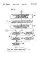
- FIGS. 3 through 5 are flowcharts of a method, according to the present invention, for determining a center position of the steering system for the motor vehicle of FIG. 1.
- the motor vehicle 10 such as an automotive vehicle is partially shown.
- the motor vehicle 10 includes wheels 12 and a steering system, generally indicated at 14, for controlling the angle of the wheels 12.
- the steering system includes a wheel speed sensor 16 for each of the wheels 12 to sense the rotational velocity of the wheels 12.
- the steering system 14 includes an electronic control unit such as a brake control module for outputting commands to a hydraulic control unit 19 for controlling a brake system (not shown) of the motor vehicle 10.
- the steering system 14 also includes a steering (wheel angle and rate) sensor 20, a lateral accelerometer 22 and a yaw rate sensor 24.
- the steering sensor 20 includes means for measuring an excursion angle of the steering system 14 from a center position determined by the steering sensor 20 in conjunction with the electronic control unit 18 as well as means, again in conjunction with the electronic control unit 18, for measuring an angular velocity which the steering system 14 (e.g., the steering shaft) is being operated.
- a steering sensor 20 is disclosed in U.S. Pat. No. 4,621,833.
- the steering sensor 20 includes a shutter wheel attached to a steering shaft, which shaft rotates in unison with a steering wheel as the steering wheel is turned by a driver of the motor vehicle 10.
- the shutter wheel has a plurality of apertures which serve to trigger the activity of detectors as the shutter wheel is rotated with the steering wheel of the motor vehicle 10.
- the steering sensor 20 is a digital device which provides a two-bit signal a plurality of times during one revolution of the steering wheel and as a result each of the signal transitions indicates for this example, 4.5 degrees of rotation of the steering wheel.
- a further discussion of the steering sensor 20 may be found in U.S. Pat. Nos. 4,722,545, 4,621,833 and 4,999,776.
- the lateral accelerometer 22 measures the lateral acceleration of the motor vehicle 10.
- the yaw rate sensor 24 measures the yaw velocity about the z axis of the motor vehicle 10.
- the electronic control unit 18 receives inputs from the wheel sensors 16, steering sensor 20, lateral accelerometer 22 and yaw rate sensor 24. In return, the electronic control unit 18 outputs commands to the hydraulic control unit 19 for controlling the brake system of the motor vehicle 10.
- the processor within the electronic control unit 18 and its associated peripheral equipment could be structured according to several different architectures. In this embodiment, however, the processor is configured so that a control program is sequentially read for each unit command from a read-only memory (ROM) which stores preset control programs. Unit commands are executed by a central processing unit (CPU).
- the processor integrally includes an input-output control circuit (I/O) for exchanging data with external devices and a random access memory (RAM) for temporarily holding data while the data is being processed.
- I/O input-output control circuit
- RAM random access memory
- a flowchart of a method, according to the present invention, for determining a center position of the steering system 14 is shown.
- the method starts in bubble 32 and advances to block 34 and defines constants and declares local and static variables.
- the method defines constants such as short to long integer scaling factor (SCALEINT), final filter constant (FILTEREND) and slightly more than half steering range (HALFSWARRANGE).
- local variables such as steering sensor counts (COUNT), vehicle longitudinal velocity (LONGV), yaw velocity (YAWV), estimated steering wheel angle based on LONGV and YAWV (ROUGHSWA), brake control active (IVDACTIVE), vehicle lateral acceleration (LATA), steering wheel angular velocity (SWAV) are defined.
- static variables such as steering wheel angle center (SWACENTER), filter setting (FILTER), maximum value of counts (COUNTMAX), minimum value of counts (COUNTMIN), maximum value of steering wheel angle center position (SWACENTERMAX), minimum value of steering wheel angle center position (SWACENTERMIN), first factor in steering center calculation (SWACTERM1), second factor in steering center calculator (SWACTERM2), and error term from truncation of steering center from long to short (SWACTRUNC) are defined.
- SWACTERM1 steering wheel angle center
- SWACTERM2 second factor in steering center calculator
- SWACTRUNC error term from truncation of steering center from long to short
- the method then advances to block 36 and reads the inputs such as COUNT, ROUGHSWA, LONGV, IVDACTIVE, LATA AND SWAV.
- the electronic control unit 18 reads a digital signal from the steering sensor 20 and reads an analog signal (YAWV) from the yaw rate sensor 24.
- the electronic control unit 18 estimates LONGV based on the input from the four wheel speed sensors 16 wherein for this example, one unit equals 0.01 kilometers/hour and estimates ROUGHSWA using LONGV and YAWV and linear interpolation from a 2-D look-up table.
- the electronic control unit 18 reads an analog signal (LATA) from the lateral acceleratometer 22 and checks the IVDACTIVE variable to see if the hydraulic control unit 19 is being actuated.
- the method advances to block 38 and determines whether this is the first pass through the algorithm, for example, by checking an initialization flag. If so, the method advances to block 40 and initializes the static variables wherein FILTER is initiated for this example, at one second and all other static variables are initiated at zero (0). After block 40 or if this is not the first pass of the method, the method advances to block 42 and determines whether the COUNT is less than (COUNTMIN) which is initially set to zero (0). If so, the method advances to block 44 and sets COUNTMIN equal to COUNT. After block 44 or if COUNT is not less than COUNTMIN, the method advances to block 46 and includes the step of determining whether COUNT is greater than COUNTMAX which is initially set to zero (0).
- the method advances to block 48 and sets COUNTMAX equal to COUNT. After block 48 or if COUNT is not greater than COUNTMAX, the method advances to block 50. It should be appreciated that based on the maximum and minimum steering rotation since start-up or key-ON of the motor vehicle 10 and knowledge of full steering travel (e.g. 920 degrees), the bounds on feasible center positions of the steering system 14 can be calculated.
- the method sets the static variable SWACENTERMAX equal to COUNTMIN plus HALFSWARANGE which is slightly more than half of the full range of the steering wheel, lock to lock.
- the method then advances to block 52 and sets the static variable SWACENTERMIN equal to COUNTMAX minus HALFSWARANGE.
- the method advances to block 54 and determines whether the read input LONGV is greater than a predetermined velocity, such as three miles per hour (3 m.p.h.), and the read input SWAV is approximately zero degrees per second and IVDACTIVE is false.
- the algorithm filters the steering wheel center when vehicle speed is above 3 m.p.h., steering wheel velocity is approximately zero (0) and the electronic control unit 18 is not actively controlling the hydraulic control unit 19 for the brake system of the motor vehicle 10.
- the method advances to block 56 (FIG. 5) to ensure the best estimate of the center position is within the known feasible boundaries (this is most important shortly after start-up and before the filter has been running long).
- the method determines whether the static variable SWACENTER is greater than the static variable SWACENTERMAX. If so, the method advances to block 58 and sets the static variable SWACENTER equal to the static variable SWACENTERMAX. After block 58 or if the static variable SWACENTER is not greater than the static variable SWACENTERMAX, the method advances to block 60 and determines whether the static variable SWACENTER is less than the static variable SWACENTERMIN. If so, the method advances to block 62 and sets the static variable SWACENTER equal to the static variable SWACENTERMIN.
- the method advances to block 64 and writes the output of the static variable SWACENTER for use by the electronic control unit 18 for controlling the hydraulic control unit 19 for brake system of the motor vehicle 10.
- the methodology then advances to bubble 66 and loops back to bubble 32 to start the method again and adjust SWACENTER.
- the method advances to block 68 and determines whether the motor vehicle 10 is driving approximately straight.
- the electronic control unit 18 determines whether the absolute value of ROUGHSWA is less than a predetermined value, such as ten degrees (10°). If so, the method advances to block 70 to set up the filter parameters in preparation for a slower responding, but more accurate, calculation of the steering center based on the steering count through a moving pole filter.
- the electronic control unit 18 determines whether FILTER is less than or equal to FILTEREND which for this example, is one minute.
- the method advances to block 72 and sets SWACTERM1 equal to SCALEINT*2/FILTER to establish one time constant and advances to block 74 and sets SWACTERM2 equal to SCALEINT minus SWACTERM1.
- the method then advances to block 76 and increments time constant by half of the loop time such as 0.0035 sec by setting FILTER equal to FILTER plus one (1). While the conditions in blocks 54 and 68 are satisfied, the FILTER time constant is incremented along with real time (one second of time goes by and FILTER increments one second). By using the term 2/FILTER, this cuts the incrementation rate of the FILTER time constant to half of real time.
- the method advances to block 78 in FIG. 5.
- the method calculates SWACENTER using a long integer filter equation.
- the calculation of the center position of the steering wheel angle is based on a low pass filter with increasing time constant starting at 0.5 seconds and ending at sixty (60) seconds.
- the method calculates SWACENTER as follows:
- the method advances to block 80 and truncates long integer to short:
- the method then advances to block 82 and calculates a truncation error:
- SWACENTER -- long is a thirty-two (32) bit value and SWACENTER is a sixteen (16) bit value and that the truncation error is saved in memory.
- the method advances to block 84 and determines whether FILTER is less than a predetermined value, such as three (3) seconds, and the absolute value of LATA is less than a predetermined value such as 0.3G's. If LATA is greater than 0.3G's, the tires begin operating in a non-linear region and the 2-D look-up table used to calculate ROUGHSWA is not sufficiently accurate. If conditions in block 84 are not satisfied, the method advances to block 56 previously described.
- a predetermined value such as three (3) seconds
- LATA is less than a predetermined value such as 0.3G's. If LATA is greater than 0.3G's, the tires begin operating in a non-linear region and the 2-D look-up table used to calculate ROUGHSWA is not sufficiently accurate. If conditions in block 84 are not satisfied, the method advances to block 56 previously described.
- the method advances to block 86 because the method may not yet have found center using the slower responding, but more accurate, method and uses a faster responding, but less accurate, method.
- the faster method uses the steering wheel angle estimate (ROUGHSWA) through a one (1) Hz filter to calculate what the steering center should be.
- the method calculates the SWACENTER -- long according to a long integer filter equation:
- the method advances to block 88 and truncates long integer to short as follows:
- the method advances to block 56 previously described. It should be appreciated that the method recalculates and adjusts the center position of the steering system 14 every loop.
Abstract
Description
SWACENTER.sub.-- long=(SWACTERM1*COUNT)+(SWACTERM2*SWACENTER)+SWACTRUNC.
SWACENTER=SWACENTER.sub.-- long/SCALEINT.
SWACTRUNC=SWACENTER.sub.-- long-(SWACENTER*SCALEINT).
SWACENTER.sub.-- long=6993*(COUNT-ROUGHSWA/4.5)+993007*SWACENTER+SWACTRUNC.
SWACENTER=SWACENTER.sub.-- long-(SWACENTER*SCALEINT).
Claims (17)
Priority Applications (4)
| Application Number | Priority Date | Filing Date | Title |
|---|---|---|---|
| US08/488,522 US5732372A (en) | 1995-06-09 | 1995-06-09 | Method for determining a center position of a vehicle steering system |
| JP8103060A JPH092320A (en) | 1995-06-09 | 1996-04-25 | Determining method of central place of automobile steering system |
| EP96303997A EP0747282B1 (en) | 1995-06-09 | 1996-06-03 | Method for determining a centre position of a vehicle steering system |
| DE69611480T DE69611480T2 (en) | 1995-06-09 | 1996-06-03 | Method for determining the center point of a vehicle steering system |
Applications Claiming Priority (1)
| Application Number | Priority Date | Filing Date | Title |
|---|---|---|---|
| US08/488,522 US5732372A (en) | 1995-06-09 | 1995-06-09 | Method for determining a center position of a vehicle steering system |
Publications (1)
| Publication Number | Publication Date |
|---|---|
| US5732372A true US5732372A (en) | 1998-03-24 |
Family
ID=23939996
Family Applications (1)
| Application Number | Title | Priority Date | Filing Date |
|---|---|---|---|
| US08/488,522 Expired - Lifetime US5732372A (en) | 1995-06-09 | 1995-06-09 | Method for determining a center position of a vehicle steering system |
Country Status (4)
| Country | Link |
|---|---|
| US (1) | US5732372A (en) |
| EP (1) | EP0747282B1 (en) |
| JP (1) | JPH092320A (en) |
| DE (1) | DE69611480T2 (en) |
Cited By (14)
| Publication number | Priority date | Publication date | Assignee | Title |
|---|---|---|---|---|
| US5948030A (en) * | 1997-07-25 | 1999-09-07 | General Motors Corporation | Steering angle determaination method and apparatus |
| USH1846H (en) * | 1999-02-02 | 2000-04-04 | Caterpillar Inc. | Electro-hydraulic steering system for an articulated vehicle |
| US6050360A (en) * | 1998-06-24 | 2000-04-18 | General Motors Corporation | Apparatus and method for producing a desired return torque in a vehicle power steering system having a rotational steering position sensor |
| US6089344A (en) * | 1998-06-01 | 2000-07-18 | Ford Global Technologies, Inc. | Method and apparatus for determining the center position of a steering system |
| US6141605A (en) * | 1999-06-25 | 2000-10-31 | Ford Global Technologies, Inc. | Determining the direction of travel of an automotive vehicle from yaw rate and relative steering wheel angle |
| US6198988B1 (en) | 1998-08-10 | 2001-03-06 | Ford Global Technologies, Inc. | Method for detecting an erroneous direction of travel signal |
| US6234520B1 (en) | 1992-05-05 | 2001-05-22 | Automotive Technologies International, Inc. | Method and apparatus for disabling an airbag system in a vehicle |
| US6429780B1 (en) * | 1999-06-22 | 2002-08-06 | Nisshinbo Industries, Inc. | Failure detection method for a steering wheel sensor |
| US20040017190A1 (en) * | 2002-07-17 | 2004-01-29 | Mcdearmon Graham F. | Apparatus and method for absolute angular position sensing |
| US20040024565A1 (en) * | 2002-08-05 | 2004-02-05 | Jingsheng Yu | Vehicle operating parameter determination system and method |
| US6789017B2 (en) | 2002-02-15 | 2004-09-07 | Robert Bosch Corporation | Vehicle steering angle position determination method |
| US20080079311A1 (en) * | 2006-08-15 | 2008-04-03 | Ford Global Technologies, Llc | Vehicle regenerative braking system and method |
| US20120041658A1 (en) * | 2010-08-16 | 2012-02-16 | Steven Paul Turner | System and method for determining a steering angle for a vehicle and system and method for controlling a vehicle based on same |
| US8583312B2 (en) * | 2011-08-22 | 2013-11-12 | Agco Corporation | Guidance system automatic wheel angle sensor calibration |
Families Citing this family (1)
| Publication number | Priority date | Publication date | Assignee | Title |
|---|---|---|---|---|
| DE10011710B4 (en) * | 2000-03-10 | 2005-07-14 | Daimlerchrysler Ag | Method for determining a center position in a vehicle steering system and steering system for carrying out the method |
Citations (18)
| Publication number | Priority date | Publication date | Assignee | Title |
|---|---|---|---|---|
| US4621833A (en) * | 1985-12-16 | 1986-11-11 | Ford Motor Company | Control system for multistable suspension unit |
| US4722545A (en) * | 1987-05-04 | 1988-02-02 | Ford Motor Company | Method and apparatus for determining the center position of a vehicular steering system |
| US4803629A (en) * | 1986-01-08 | 1989-02-07 | Hitachi, Ltd. | Power steering apparatus and control system for power steering apparatus having a steering wheel angle detection device |
| EP0321082A2 (en) * | 1987-12-16 | 1989-06-21 | Ford Motor Company Limited | Method and apparatus for determining the center position of a vehicular steering system |
| EP0359673A2 (en) * | 1988-09-16 | 1990-03-21 | Nissan Motor Co., Ltd. | Apparatus and method for detecting neutral steering angle of steering wheel system for vehicle |
| US4961474A (en) * | 1988-07-11 | 1990-10-09 | Koyo Seiko Co., Ltd. | Steering angle middle point detecting apparatus |
| DE4015618A1 (en) * | 1989-05-15 | 1990-11-22 | Nissan Motor | DEVICE FOR DETERMINING THE NEUTRAL POSITION OF A STEERING ACTUATOR |
| US4999776A (en) * | 1989-11-30 | 1991-03-12 | Ford Motor Company | Method and apparatus for determining the center position of a vehicular steering system |
| JPH03128768A (en) * | 1989-08-23 | 1991-05-31 | Nissan Motor Co Ltd | Neutral steering angle estimating device |
| US5121322A (en) * | 1989-05-15 | 1992-06-09 | Nissan Motor Co., Ltd. | Steering handle neutral position estimating apparatus |
| DE4130142A1 (en) * | 1991-09-11 | 1993-03-18 | Fichtel & Sachs Ag | Null point correction appts. for motor vehicle steering angle sensor - converts continuous steering angle signal into instantaneous values which are averaged by computer for derivation of correction values |
| EP0546789A2 (en) * | 1991-12-10 | 1993-06-16 | Mitsubishi Jidosha Kogyo Kabushiki Kaisha | Method and system for estimating the neutral point of a steering wheel |
| US5243188A (en) * | 1991-09-26 | 1993-09-07 | Kabushiki Kaisha Tokai Rika Denki Seisakusho | Neutral position detector for steering wheels having a first and second rotors with aligned slots |
| US5253172A (en) * | 1990-01-25 | 1993-10-12 | Mitsubishi Jidosha Kogyo Kabushiki Kaisha | Method and apparatus for learning neutral position of vehicle steering angle |
| JPH06255530A (en) * | 1993-03-02 | 1994-09-13 | Toyota Autom Loom Works Ltd | Neutral position detecting device for steered road wheel in industrial vehicle |
| US5422810A (en) * | 1994-05-05 | 1995-06-06 | Ford Motor Company | Method and apparatus for determining steering position of automotive steering mechanism |
| US5434784A (en) * | 1994-08-26 | 1995-07-18 | General Motors Corporation | Vehicle steering wheel position sensing apparatus |
| US5465210A (en) * | 1994-08-18 | 1995-11-07 | General Motors Corporation | Method for determining a vehicle steering wheel center position |
Family Cites Families (1)
| Publication number | Priority date | Publication date | Assignee | Title |
|---|---|---|---|---|
| JPH04252912A (en) * | 1991-01-29 | 1992-09-08 | Nippondenso Co Ltd | Steering position detector for automobile |
-
1995
- 1995-06-09 US US08/488,522 patent/US5732372A/en not_active Expired - Lifetime
-
1996
- 1996-04-25 JP JP8103060A patent/JPH092320A/en active Pending
- 1996-06-03 EP EP96303997A patent/EP0747282B1/en not_active Expired - Lifetime
- 1996-06-03 DE DE69611480T patent/DE69611480T2/en not_active Expired - Fee Related
Patent Citations (21)
| Publication number | Priority date | Publication date | Assignee | Title |
|---|---|---|---|---|
| US4621833A (en) * | 1985-12-16 | 1986-11-11 | Ford Motor Company | Control system for multistable suspension unit |
| US4803629A (en) * | 1986-01-08 | 1989-02-07 | Hitachi, Ltd. | Power steering apparatus and control system for power steering apparatus having a steering wheel angle detection device |
| US4722545A (en) * | 1987-05-04 | 1988-02-02 | Ford Motor Company | Method and apparatus for determining the center position of a vehicular steering system |
| EP0321082A2 (en) * | 1987-12-16 | 1989-06-21 | Ford Motor Company Limited | Method and apparatus for determining the center position of a vehicular steering system |
| US4961474A (en) * | 1988-07-11 | 1990-10-09 | Koyo Seiko Co., Ltd. | Steering angle middle point detecting apparatus |
| US5032996A (en) * | 1988-09-16 | 1991-07-16 | Nissan Motor Company, Limited | Apparatus and method for detecting neutral steering angle of steering wheel system for vehicle |
| EP0359673A2 (en) * | 1988-09-16 | 1990-03-21 | Nissan Motor Co., Ltd. | Apparatus and method for detecting neutral steering angle of steering wheel system for vehicle |
| US5065323A (en) * | 1989-05-15 | 1991-11-12 | Nissan Motor Co., Ltd. | Steering handle neutral position estimating apparatus |
| DE4015618A1 (en) * | 1989-05-15 | 1990-11-22 | Nissan Motor | DEVICE FOR DETERMINING THE NEUTRAL POSITION OF A STEERING ACTUATOR |
| US5121322A (en) * | 1989-05-15 | 1992-06-09 | Nissan Motor Co., Ltd. | Steering handle neutral position estimating apparatus |
| JPH03128768A (en) * | 1989-08-23 | 1991-05-31 | Nissan Motor Co Ltd | Neutral steering angle estimating device |
| US4999776A (en) * | 1989-11-30 | 1991-03-12 | Ford Motor Company | Method and apparatus for determining the center position of a vehicular steering system |
| US5253172A (en) * | 1990-01-25 | 1993-10-12 | Mitsubishi Jidosha Kogyo Kabushiki Kaisha | Method and apparatus for learning neutral position of vehicle steering angle |
| DE4130142A1 (en) * | 1991-09-11 | 1993-03-18 | Fichtel & Sachs Ag | Null point correction appts. for motor vehicle steering angle sensor - converts continuous steering angle signal into instantaneous values which are averaged by computer for derivation of correction values |
| US5243188A (en) * | 1991-09-26 | 1993-09-07 | Kabushiki Kaisha Tokai Rika Denki Seisakusho | Neutral position detector for steering wheels having a first and second rotors with aligned slots |
| EP0546789A2 (en) * | 1991-12-10 | 1993-06-16 | Mitsubishi Jidosha Kogyo Kabushiki Kaisha | Method and system for estimating the neutral point of a steering wheel |
| US5311432A (en) * | 1991-12-10 | 1994-05-10 | Mitsubishi Jidosha Kogyo Kabushiki Kaisha | Method and system for estimating the neutral point of a steering wheel |
| JPH06255530A (en) * | 1993-03-02 | 1994-09-13 | Toyota Autom Loom Works Ltd | Neutral position detecting device for steered road wheel in industrial vehicle |
| US5422810A (en) * | 1994-05-05 | 1995-06-06 | Ford Motor Company | Method and apparatus for determining steering position of automotive steering mechanism |
| US5465210A (en) * | 1994-08-18 | 1995-11-07 | General Motors Corporation | Method for determining a vehicle steering wheel center position |
| US5434784A (en) * | 1994-08-26 | 1995-07-18 | General Motors Corporation | Vehicle steering wheel position sensing apparatus |
Cited By (16)
| Publication number | Priority date | Publication date | Assignee | Title |
|---|---|---|---|---|
| US6234520B1 (en) | 1992-05-05 | 2001-05-22 | Automotive Technologies International, Inc. | Method and apparatus for disabling an airbag system in a vehicle |
| US5948030A (en) * | 1997-07-25 | 1999-09-07 | General Motors Corporation | Steering angle determaination method and apparatus |
| US6089344A (en) * | 1998-06-01 | 2000-07-18 | Ford Global Technologies, Inc. | Method and apparatus for determining the center position of a steering system |
| US6050360A (en) * | 1998-06-24 | 2000-04-18 | General Motors Corporation | Apparatus and method for producing a desired return torque in a vehicle power steering system having a rotational steering position sensor |
| US6198988B1 (en) | 1998-08-10 | 2001-03-06 | Ford Global Technologies, Inc. | Method for detecting an erroneous direction of travel signal |
| USH1846H (en) * | 1999-02-02 | 2000-04-04 | Caterpillar Inc. | Electro-hydraulic steering system for an articulated vehicle |
| US6429780B1 (en) * | 1999-06-22 | 2002-08-06 | Nisshinbo Industries, Inc. | Failure detection method for a steering wheel sensor |
| US6141605A (en) * | 1999-06-25 | 2000-10-31 | Ford Global Technologies, Inc. | Determining the direction of travel of an automotive vehicle from yaw rate and relative steering wheel angle |
| US6789017B2 (en) | 2002-02-15 | 2004-09-07 | Robert Bosch Corporation | Vehicle steering angle position determination method |
| US20040017190A1 (en) * | 2002-07-17 | 2004-01-29 | Mcdearmon Graham F. | Apparatus and method for absolute angular position sensing |
| US20040024565A1 (en) * | 2002-08-05 | 2004-02-05 | Jingsheng Yu | Vehicle operating parameter determination system and method |
| US6816799B2 (en) | 2002-08-05 | 2004-11-09 | Robert Bosch Corporation | Vehicle operating parameter determination system and method |
| US20080079311A1 (en) * | 2006-08-15 | 2008-04-03 | Ford Global Technologies, Llc | Vehicle regenerative braking system and method |
| US20120041658A1 (en) * | 2010-08-16 | 2012-02-16 | Steven Paul Turner | System and method for determining a steering angle for a vehicle and system and method for controlling a vehicle based on same |
| US9205869B2 (en) * | 2010-08-16 | 2015-12-08 | Honda Motor Co., Ltd. | System and method for determining a steering angle for a vehicle and system and method for controlling a vehicle based on same |
| US8583312B2 (en) * | 2011-08-22 | 2013-11-12 | Agco Corporation | Guidance system automatic wheel angle sensor calibration |
Also Published As
| Publication number | Publication date |
|---|---|
| DE69611480D1 (en) | 2001-02-15 |
| JPH092320A (en) | 1997-01-07 |
| EP0747282A1 (en) | 1996-12-11 |
| EP0747282B1 (en) | 2001-01-10 |
| DE69611480T2 (en) | 2001-05-23 |
Similar Documents
| Publication | Publication Date | Title |
|---|---|---|
| US5732372A (en) | Method for determining a center position of a vehicle steering system | |
| US5809434A (en) | Method and apparatus for dynamically determically determining an operating state of a motor vehicle | |
| US5742919A (en) | Method and apparatus for dynamically determining a lateral velocity of a motor vehicle | |
| US5857160A (en) | Sensor-responsive control method and apparatus | |
| US5977869A (en) | Motor vehicle speed control method and arrangement | |
| EP0983919B1 (en) | A method for detecting a bank angle experienced by a moving vehicle | |
| US5465210A (en) | Method for determining a vehicle steering wheel center position | |
| EP0799755A2 (en) | Method for determining steering position of automotive steering mechanism | |
| JPH11348811A (en) | Method and device for determining center position of steering system | |
| JPH09118212A (en) | Side slip speed estimating device of car body | |
| US7099759B2 (en) | Method and apparatus for estimating steering behavior for integrated chassis control | |
| JP3236003B1 (en) | Road surface friction coefficient estimation device for vehicles | |
| US5895433A (en) | Vehicle chassis system control method and apparatus | |
| US5040115A (en) | System for monitoring vehicle slip angle | |
| US5343400A (en) | Method for detecting relative travel direction of a vehicle | |
| JPH09505891A (en) | Circuit device for evaluating the signal of the yawing speed sensor | |
| JP3165045B2 (en) | Angular velocity data correction device | |
| US5826204A (en) | Circuit configuration for evaluation of the signals from a yaw rate sensor | |
| US20050182542A1 (en) | Device and procedure for a steering support for vehicles with electromechanical steering system | |
| JP3319989B2 (en) | Sensor detection value correction device in vehicle motion control device | |
| JPH08332934A (en) | Skidding condition quantity detection device for vehicle | |
| JPH10315999A (en) | Steering torque detector and steering torque detection method | |
| JPH11227489A (en) | Critical operation judging device for vehicle | |
| JP3033397B2 (en) | Abnormality detection device for yaw rate sensor output | |
| JPH0783949A (en) | Apparatus for detecting yaw rate of vehicle |
Legal Events
| Date | Code | Title | Description |
|---|---|---|---|
| AS | Assignment |
Owner name: FORD MOTOR COMPANY, MICHIGAN Free format text: ASSIGNMENT OF ASSIGNORS INTEREST;ASSIGNOR:MARSDEN, DOUGLAS W.;REEL/FRAME:007649/0358 Effective date: 19950605 |
|
| AS | Assignment |
Owner name: FORD GLOBAL TECHNOLOGIES, INC., MICHIGAN Free format text: ASSIGNMENT OF ASSIGNORS INTEREST;ASSIGNOR:FORD MOTOR COMPANY;REEL/FRAME:008564/0053 Effective date: 19970430 |
|
| STCF | Information on status: patent grant |
Free format text: PATENTED CASE |
|
| FPAY | Fee payment |
Year of fee payment: 4 |
|
| FPAY | Fee payment |
Year of fee payment: 8 |
|
| FPAY | Fee payment |
Year of fee payment: 12 |