EP0542423A2 - Verbesserter Verbinder für Aufzeichnungsplattenabe - Google Patents
Verbesserter Verbinder für Aufzeichnungsplattenabe Download PDFInfo
- Publication number
- EP0542423A2 EP0542423A2 EP92309223A EP92309223A EP0542423A2 EP 0542423 A2 EP0542423 A2 EP 0542423A2 EP 92309223 A EP92309223 A EP 92309223A EP 92309223 A EP92309223 A EP 92309223A EP 0542423 A2 EP0542423 A2 EP 0542423A2
- Authority
- EP
- European Patent Office
- Prior art keywords
- hub
- substrate
- spheroids
- adhesive
- cross
- Prior art date
- Legal status (The legal status is an assumption and is not a legal conclusion. Google has not performed a legal analysis and makes no representation as to the accuracy of the status listed.)
- Granted
Links
- 239000000758 substrate Substances 0.000 claims abstract description 59
- 239000010410 layer Substances 0.000 claims abstract description 33
- 239000000853 adhesive Substances 0.000 claims abstract description 29
- 230000001070 adhesive effect Effects 0.000 claims abstract description 29
- 239000011521 glass Substances 0.000 claims abstract description 21
- 239000002356 single layer Substances 0.000 claims abstract description 5
- 239000004593 Epoxy Substances 0.000 claims description 35
- 238000000034 method Methods 0.000 claims description 12
- 229910052782 aluminium Inorganic materials 0.000 claims description 3
- XAGFODPZIPBFFR-UHFFFAOYSA-N aluminium Chemical compound [Al] XAGFODPZIPBFFR-UHFFFAOYSA-N 0.000 claims description 3
- 238000009826 distribution Methods 0.000 claims description 3
- 239000000919 ceramic Substances 0.000 claims description 2
- 239000000463 material Substances 0.000 claims description 2
- QXJJQWWVWRCVQT-UHFFFAOYSA-K calcium;sodium;phosphate Chemical compound [Na+].[Ca+2].[O-]P([O-])([O-])=O QXJJQWWVWRCVQT-UHFFFAOYSA-K 0.000 description 16
- 230000013011 mating Effects 0.000 description 10
- 239000000203 mixture Substances 0.000 description 8
- 125000006850 spacer group Chemical group 0.000 description 7
- 239000010408 film Substances 0.000 description 5
- 230000003287 optical effect Effects 0.000 description 5
- 230000002093 peripheral effect Effects 0.000 description 3
- 239000010965 430 stainless steel Substances 0.000 description 2
- 239000012790 adhesive layer Substances 0.000 description 2
- 238000005094 computer simulation Methods 0.000 description 2
- 229920006332 epoxy adhesive Polymers 0.000 description 2
- 238000004519 manufacturing process Methods 0.000 description 2
- 238000005065 mining Methods 0.000 description 2
- 229920000515 polycarbonate Polymers 0.000 description 2
- 239000004417 polycarbonate Substances 0.000 description 2
- 239000004820 Pressure-sensitive adhesive Substances 0.000 description 1
- 238000004590 computer program Methods 0.000 description 1
- 238000010276 construction Methods 0.000 description 1
- 238000005137 deposition process Methods 0.000 description 1
- 239000000945 filler Substances 0.000 description 1
- 238000010030 laminating Methods 0.000 description 1
- 229910052751 metal Inorganic materials 0.000 description 1
- 239000002184 metal Substances 0.000 description 1
- 229920003229 poly(methyl methacrylate) Polymers 0.000 description 1
- 229920000728 polyester Polymers 0.000 description 1
- 229920006254 polymer film Polymers 0.000 description 1
- 239000004926 polymethyl methacrylate Substances 0.000 description 1
- 238000004544 sputter deposition Methods 0.000 description 1
- 239000010935 stainless steel Substances 0.000 description 1
- 229910001220 stainless steel Inorganic materials 0.000 description 1
- 239000010409 thin film Substances 0.000 description 1
- 230000009974 thixotropic effect Effects 0.000 description 1
Images
Classifications
-
- G—PHYSICS
- G11—INFORMATION STORAGE
- G11B—INFORMATION STORAGE BASED ON RELATIVE MOVEMENT BETWEEN RECORD CARRIER AND TRANSDUCER
- G11B23/00—Record carriers not specific to the method of recording or reproducing; Accessories, e.g. containers, specially adapted for co-operation with the recording or reproducing apparatus ; Intermediate mediums; Apparatus or processes specially adapted for their manufacture
-
- B—PERFORMING OPERATIONS; TRANSPORTING
- B29—WORKING OF PLASTICS; WORKING OF SUBSTANCES IN A PLASTIC STATE IN GENERAL
- B29C—SHAPING OR JOINING OF PLASTICS; SHAPING OF MATERIAL IN A PLASTIC STATE, NOT OTHERWISE PROVIDED FOR; AFTER-TREATMENT OF THE SHAPED PRODUCTS, e.g. REPAIRING
- B29C66/00—General aspects of processes or apparatus for joining preformed parts
- B29C66/40—General aspects of joining substantially flat articles, e.g. plates, sheets or web-like materials; Making flat seams in tubular or hollow articles; Joining single elements to substantially flat surfaces
- B29C66/47—Joining single elements to sheets, plates or other substantially flat surfaces
- B29C66/474—Joining single elements to sheets, plates or other substantially flat surfaces said single elements being substantially non-flat
-
- B—PERFORMING OPERATIONS; TRANSPORTING
- B29—WORKING OF PLASTICS; WORKING OF SUBSTANCES IN A PLASTIC STATE IN GENERAL
- B29C—SHAPING OR JOINING OF PLASTICS; SHAPING OF MATERIAL IN A PLASTIC STATE, NOT OTHERWISE PROVIDED FOR; AFTER-TREATMENT OF THE SHAPED PRODUCTS, e.g. REPAIRING
- B29C65/00—Joining or sealing of preformed parts, e.g. welding of plastics materials; Apparatus therefor
- B29C65/48—Joining or sealing of preformed parts, e.g. welding of plastics materials; Apparatus therefor using adhesives, i.e. using supplementary joining material; solvent bonding
- B29C65/4805—Joining or sealing of preformed parts, e.g. welding of plastics materials; Apparatus therefor using adhesives, i.e. using supplementary joining material; solvent bonding characterised by the type of adhesives
- B29C65/483—Reactive adhesives, e.g. chemically curing adhesives
-
- B—PERFORMING OPERATIONS; TRANSPORTING
- B29—WORKING OF PLASTICS; WORKING OF SUBSTANCES IN A PLASTIC STATE IN GENERAL
- B29C—SHAPING OR JOINING OF PLASTICS; SHAPING OF MATERIAL IN A PLASTIC STATE, NOT OTHERWISE PROVIDED FOR; AFTER-TREATMENT OF THE SHAPED PRODUCTS, e.g. REPAIRING
- B29C66/00—General aspects of processes or apparatus for joining preformed parts
- B29C66/01—General aspects dealing with the joint area or with the area to be joined
- B29C66/05—Particular design of joint configurations
- B29C66/10—Particular design of joint configurations particular design of the joint cross-sections
- B29C66/11—Joint cross-sections comprising a single joint-segment, i.e. one of the parts to be joined comprising a single joint-segment in the joint cross-section
- B29C66/112—Single lapped joints
- B29C66/1122—Single lap to lap joints, i.e. overlap joints
-
- G—PHYSICS
- G11—INFORMATION STORAGE
- G11B—INFORMATION STORAGE BASED ON RELATIVE MOVEMENT BETWEEN RECORD CARRIER AND TRANSDUCER
- G11B11/00—Recording on or reproducing from the same record carrier wherein for these two operations the methods are covered by different main groups of groups G11B3/00 - G11B7/00 or by different subgroups of group G11B9/00; Record carriers therefor
- G11B11/10—Recording on or reproducing from the same record carrier wherein for these two operations the methods are covered by different main groups of groups G11B3/00 - G11B7/00 or by different subgroups of group G11B9/00; Record carriers therefor using recording by magnetic means or other means for magnetisation or demagnetisation of a record carrier, e.g. light induced spin magnetisation; Demagnetisation by thermal or stress means in the presence or not of an orienting magnetic field
- G11B11/105—Recording on or reproducing from the same record carrier wherein for these two operations the methods are covered by different main groups of groups G11B3/00 - G11B7/00 or by different subgroups of group G11B9/00; Record carriers therefor using recording by magnetic means or other means for magnetisation or demagnetisation of a record carrier, e.g. light induced spin magnetisation; Demagnetisation by thermal or stress means in the presence or not of an orienting magnetic field using a beam of light or a magnetic field for recording by change of magnetisation and a beam of light for reproducing, i.e. magneto-optical, e.g. light-induced thermomagnetic recording, spin magnetisation recording, Kerr or Faraday effect reproducing
- G11B11/10582—Record carriers characterised by the selection of the material or by the structure or form
-
- G—PHYSICS
- G11—INFORMATION STORAGE
- G11B—INFORMATION STORAGE BASED ON RELATIVE MOVEMENT BETWEEN RECORD CARRIER AND TRANSDUCER
- G11B23/00—Record carriers not specific to the method of recording or reproducing; Accessories, e.g. containers, specially adapted for co-operation with the recording or reproducing apparatus ; Intermediate mediums; Apparatus or processes specially adapted for their manufacture
- G11B23/0014—Record carriers not specific to the method of recording or reproducing; Accessories, e.g. containers, specially adapted for co-operation with the recording or reproducing apparatus ; Intermediate mediums; Apparatus or processes specially adapted for their manufacture record carriers not specifically of filamentary or web form
- G11B23/0021—Record carriers not specific to the method of recording or reproducing; Accessories, e.g. containers, specially adapted for co-operation with the recording or reproducing apparatus ; Intermediate mediums; Apparatus or processes specially adapted for their manufacture record carriers not specifically of filamentary or web form discs
- G11B23/0028—Details
- G11B23/0035—Details means incorporated in the disc, e.g. hub, to enable its guiding, loading or driving
-
- G—PHYSICS
- G11—INFORMATION STORAGE
- G11B—INFORMATION STORAGE BASED ON RELATIVE MOVEMENT BETWEEN RECORD CARRIER AND TRANSDUCER
- G11B7/00—Recording or reproducing by optical means, e.g. recording using a thermal beam of optical radiation by modifying optical properties or the physical structure, reproducing using an optical beam at lower power by sensing optical properties; Record carriers therefor
- G11B7/24—Record carriers characterised by shape, structure or physical properties, or by the selection of the material
- G11B7/26—Apparatus or processes specially adapted for the manufacture of record carriers
-
- B—PERFORMING OPERATIONS; TRANSPORTING
- B29—WORKING OF PLASTICS; WORKING OF SUBSTANCES IN A PLASTIC STATE IN GENERAL
- B29C—SHAPING OR JOINING OF PLASTICS; SHAPING OF MATERIAL IN A PLASTIC STATE, NOT OTHERWISE PROVIDED FOR; AFTER-TREATMENT OF THE SHAPED PRODUCTS, e.g. REPAIRING
- B29C65/00—Joining or sealing of preformed parts, e.g. welding of plastics materials; Apparatus therefor
- B29C65/48—Joining or sealing of preformed parts, e.g. welding of plastics materials; Apparatus therefor using adhesives, i.e. using supplementary joining material; solvent bonding
- B29C65/4805—Joining or sealing of preformed parts, e.g. welding of plastics materials; Apparatus therefor using adhesives, i.e. using supplementary joining material; solvent bonding characterised by the type of adhesives
- B29C65/481—Non-reactive adhesives, e.g. physically hardening adhesives
- B29C65/4825—Pressure sensitive adhesives
-
- B—PERFORMING OPERATIONS; TRANSPORTING
- B29—WORKING OF PLASTICS; WORKING OF SUBSTANCES IN A PLASTIC STATE IN GENERAL
- B29C—SHAPING OR JOINING OF PLASTICS; SHAPING OF MATERIAL IN A PLASTIC STATE, NOT OTHERWISE PROVIDED FOR; AFTER-TREATMENT OF THE SHAPED PRODUCTS, e.g. REPAIRING
- B29C65/00—Joining or sealing of preformed parts, e.g. welding of plastics materials; Apparatus therefor
- B29C65/48—Joining or sealing of preformed parts, e.g. welding of plastics materials; Apparatus therefor using adhesives, i.e. using supplementary joining material; solvent bonding
- B29C65/4805—Joining or sealing of preformed parts, e.g. welding of plastics materials; Apparatus therefor using adhesives, i.e. using supplementary joining material; solvent bonding characterised by the type of adhesives
- B29C65/483—Reactive adhesives, e.g. chemically curing adhesives
- B29C65/485—Multi-component adhesives, i.e. chemically curing as a result of the mixing of said multi-components
-
- B—PERFORMING OPERATIONS; TRANSPORTING
- B29—WORKING OF PLASTICS; WORKING OF SUBSTANCES IN A PLASTIC STATE IN GENERAL
- B29C—SHAPING OR JOINING OF PLASTICS; SHAPING OF MATERIAL IN A PLASTIC STATE, NOT OTHERWISE PROVIDED FOR; AFTER-TREATMENT OF THE SHAPED PRODUCTS, e.g. REPAIRING
- B29C65/00—Joining or sealing of preformed parts, e.g. welding of plastics materials; Apparatus therefor
- B29C65/48—Joining or sealing of preformed parts, e.g. welding of plastics materials; Apparatus therefor using adhesives, i.e. using supplementary joining material; solvent bonding
- B29C65/4865—Joining or sealing of preformed parts, e.g. welding of plastics materials; Apparatus therefor using adhesives, i.e. using supplementary joining material; solvent bonding containing additives
- B29C65/487—Joining or sealing of preformed parts, e.g. welding of plastics materials; Apparatus therefor using adhesives, i.e. using supplementary joining material; solvent bonding containing additives characterised by their shape, e.g. being fibres or being spherical
- B29C65/4875—Joining or sealing of preformed parts, e.g. welding of plastics materials; Apparatus therefor using adhesives, i.e. using supplementary joining material; solvent bonding containing additives characterised by their shape, e.g. being fibres or being spherical being spherical, e.g. particles or powders
-
- B—PERFORMING OPERATIONS; TRANSPORTING
- B29—WORKING OF PLASTICS; WORKING OF SUBSTANCES IN A PLASTIC STATE IN GENERAL
- B29C—SHAPING OR JOINING OF PLASTICS; SHAPING OF MATERIAL IN A PLASTIC STATE, NOT OTHERWISE PROVIDED FOR; AFTER-TREATMENT OF THE SHAPED PRODUCTS, e.g. REPAIRING
- B29C65/00—Joining or sealing of preformed parts, e.g. welding of plastics materials; Apparatus therefor
- B29C65/48—Joining or sealing of preformed parts, e.g. welding of plastics materials; Apparatus therefor using adhesives, i.e. using supplementary joining material; solvent bonding
- B29C65/4865—Joining or sealing of preformed parts, e.g. welding of plastics materials; Apparatus therefor using adhesives, i.e. using supplementary joining material; solvent bonding containing additives
- B29C65/4885—Joining or sealing of preformed parts, e.g. welding of plastics materials; Apparatus therefor using adhesives, i.e. using supplementary joining material; solvent bonding containing additives characterised by their composition being non-plastics
-
- B—PERFORMING OPERATIONS; TRANSPORTING
- B29—WORKING OF PLASTICS; WORKING OF SUBSTANCES IN A PLASTIC STATE IN GENERAL
- B29C—SHAPING OR JOINING OF PLASTICS; SHAPING OF MATERIAL IN A PLASTIC STATE, NOT OTHERWISE PROVIDED FOR; AFTER-TREATMENT OF THE SHAPED PRODUCTS, e.g. REPAIRING
- B29C66/00—General aspects of processes or apparatus for joining preformed parts
- B29C66/70—General aspects of processes or apparatus for joining preformed parts characterised by the composition, physical properties or the structure of the material of the parts to be joined; Joining with non-plastics material
- B29C66/71—General aspects of processes or apparatus for joining preformed parts characterised by the composition, physical properties or the structure of the material of the parts to be joined; Joining with non-plastics material characterised by the composition of the plastics material of the parts to be joined
-
- B—PERFORMING OPERATIONS; TRANSPORTING
- B29—WORKING OF PLASTICS; WORKING OF SUBSTANCES IN A PLASTIC STATE IN GENERAL
- B29C—SHAPING OR JOINING OF PLASTICS; SHAPING OF MATERIAL IN A PLASTIC STATE, NOT OTHERWISE PROVIDED FOR; AFTER-TREATMENT OF THE SHAPED PRODUCTS, e.g. REPAIRING
- B29C66/00—General aspects of processes or apparatus for joining preformed parts
- B29C66/70—General aspects of processes or apparatus for joining preformed parts characterised by the composition, physical properties or the structure of the material of the parts to be joined; Joining with non-plastics material
- B29C66/72—General aspects of processes or apparatus for joining preformed parts characterised by the composition, physical properties or the structure of the material of the parts to be joined; Joining with non-plastics material characterised by the structure of the material of the parts to be joined
- B29C66/723—General aspects of processes or apparatus for joining preformed parts characterised by the composition, physical properties or the structure of the material of the parts to be joined; Joining with non-plastics material characterised by the structure of the material of the parts to be joined being multi-layered
-
- B—PERFORMING OPERATIONS; TRANSPORTING
- B29—WORKING OF PLASTICS; WORKING OF SUBSTANCES IN A PLASTIC STATE IN GENERAL
- B29L—INDEXING SCHEME ASSOCIATED WITH SUBCLASS B29C, RELATING TO PARTICULAR ARTICLES
- B29L2017/00—Carriers for sound or information
- B29L2017/001—Carriers of records containing fine grooves or impressions, e.g. disc records for needle playback, cylinder records
- B29L2017/003—Records or discs
- B29L2017/005—CD''s, DVD''s
Definitions
- the present invention relates to magnetic, optical, and magneto-optic recording media disks, and in particular, it relates to bonding hubs to disk substrates.
- Such recording media disks more generally consist of three elements, a substrate having one or more recording layers, a hub, and an adhesive which secures the substrate to the hub.
- the substrate is made from polymethylmethacrylate, polycarbonate, polyester, aluminum or glass.
- the magneto-optic layer is deposited through well-known methods of sputtering on to the substrate.
- a hub is then applied to the substrate.
- the hub generally includes a metal centering disk embedded in a polymeric flange.
- the typical method for attaching the hub to the substrate is to place a ring of polymer film with a pressure-sensitive adhesive coated to both sides between the substrate and the hub to secure the hub to the substrate.
- the present invention includes a recording disk having a substrate with a magnetic, optical or magneto-optic medium bonded to a hub by a bond layer including a cross-linked adhesive and a monolayer of glass spheroids dispersed within the cross-linked adhesive.
- the bond layer thickness is less than one millimeter and is no less than the effective maximum diameter of the spheroids.
- the inventive construction facilitates uniform axial spacing of the hub from the recording disk substrate, and results in increased bond strength.
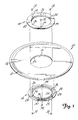
- Figure 1 is an exploded perspective view of a disk within the scope of the present invention.
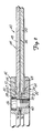
- Figure 2 is a partial cross-sectional view of a disk design with mechanical spacer ridges 62 and 64 on hub 42 for uniform bond line between the hub and substrate.
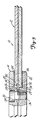
- Figure 3 is a partial cross-sectional view of a disk of the present invention.
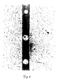
- Figure 4 is a photomicrograph illustrating the bond line thickness of the glass filled epoxy layer of the present invention at a magnification of about 75x on a sample bond between two glass slides.
- the disk of the present invention is generally indicated as 10 in Figure 1.
- the disk 10 includes a substrate 12 and a hub 14 (in two parts) that is secured to the substrate 12.
- the substrate 12 is in the form of a round disk having a centrally disposed opening 16 in Figure 1.
- the disk includes a substrate layer made of glass, however, other substrates such as polycarbonate may also be used.
- Other substrates such as are listed in the Freese et al U.S. Patent 4,569,881, are also within the scope of the present invention.
- the substrate 12 is approximately 14 inches (356 mm) in diameter.
- the substrate includes a magneto-optic film layer 18.
- Magneto-optic film layers that are suitable for use in the present invention are well known in the art. Magneto-optic thin film recording media and deposition processes are described in the Freese et al U.S. Patent 4,569,881, and the Gardner U.S. Patent 4,615,944.
- the magneto-optic film layer preferably includes both read and write capabilities and has an error rate performance equivalent to commercially available magneto-optic films.
- the substrate is in the form of a double-sided disk, that is, having the capability of recording data on both sides of the disk.
- Double-sided disks are well known in the art, and can be formed by laminating two substrate layers together with respective magneto-optic film layers disposed thereon.
- the hub 14 includes a first hub half 20 and a second hub half 22.
- the hub halves are made of #430 stainless steel. Since both hub halves 20 and 22 are similar, hub half 22 will be described with the understanding that hub half 20 has similar parts.
- the hub half 22 includes an annular outer flange portion 24 for engaging an inner peripheral top or bottom edge surface portion 26 of the substrate 12.
- the hub half 22 further includes an annular shoulder 25, an annular mating surface 28, and an inner annular mating surface 30.
- the hub halves 20 and 22 are secured to each other, and thereby secured to the substrate 12, by screws 32 extending through apertures 34 in one hub half and threadably engaging apertures 36 in the other hub half.
- the apertures 34 are disposed along the mating surface 28 and spaced approximately 120 degrees from each other.
- the threaded apertures 36 are disposed along the mating surface 28 at approximately 120 degrees from each other and approximately 60 degrees from adjacent apertures 34 on the same hub half.
- Three screws 32 are disposed through respective apertures 34 in each hub half 20 and 22 to threadably engage threaded apertures 36 in the other hub half. Aligning the apertures 34 on the hub half 20 with the threaded apertures 36 on the hub half 22 also then aligns the threaded apertures on the hub half 20 with the apertures 34 on the hub half 22.
- the embodiment 40 illustrates a method of adhering a hub 42 to a substrate 44 comprising adhesive layer 46 disposed between and bonding two single-sided magneto-optic disks 48 and 50.
- the hub 42 includes a first hub half 52 and a second hub half 54 that are secured to each other and to the substrate 44.
- the hub halves 52 and 54 are in part secured to each other by screws 56 extending through apertures 58 in one hub half and threadably engaging a threaded aperture 60 in the other hub half in a manner similar to the one described previously with reference to the hub halves illustrated in Figure 1.
- Hub halves 52 and 54 include oppositely facing annular spacers or ridges 62 and 64 that directly contact oppositely facing surfaces of the substrate 44.
- the hub halves 52 and 54 further include recessed annular peripheral surfaces 66 and 68, respectively, disposed on an outer side of the spacers 62 and 64, and inner recessed surfaces 70 and 72 disposed on an inner side of the spacers 62 and 64, all respectively.
- Each hub half 52 and 54 further includes innermost recessed surfaces 74 and 76 that are disposed inwardly of recessed surfaces 70 and 72.
- the recessed surfaces 74 and 76, 70 and 72, and 66 and 68 form annular spaces in which an adhesive 78 is inserted to secure the two hub halves 52 and 54 together and to secure the hubs halves to the substrate 44.
- the annular spacers 62 and 64 attempt to provide as uniform a spacing as possible between the substrate and the recessed surfaces so that a uniform adhesive thickness or "bond line" is formed. A uniform bond line is desired so that optimum adhesive strength of the epoxy is obtained.
- Areas 80 and 82 include spacers 62 and 64 and epoxy filled spaces proximate to the spacers.
- Suitable software for computer modeling is available under the trademark ANSYS from Swanson Analysis Systems, Inc., of Houston, Pennsylvania. Utilizing the ANSYS software predicted that high stresses will be present at high temperature extremes (e.g. 77°C) and to a lesser degree at lower temperature extremes (-57°C).
- the present invention provides uniform bond lines 84 and 86.
- the uniform bond lines 84 and 86 are achieved by applying a glass-filled adhesive between the outer flange portion 24 of the hub halves 20 and 22 and the substrate 10. Glass spheres in the adhesive force the substrate and the hub halves in parallel relationship with each other, and eliminate the need for mechanical jigs to ensure a parallel relationship in configurations such as illustrated in Figure 2.
- a non-filled adhesive layer is applied between mating surfaces 28 of the hub halves 20 and 22. No adhesive is applied between an inner peripheral edge 88 of the substrate 10 and the annular shoulders 25 of the hub halves 20 and 22 thereby providing an air gap between the shoulders 25 and the edge 88.
- the thickness of bond lines 84 and 86 is generally less than one millimeter.
- the bond layer thickness is between 200 and 350 micrometers.
- the glass-filled adhesive epoxy includes glass spheres selected to produce a bond layer having a thickness of approximately 250 micrometers (0.010 inches). Glass spheres having a nominal diameter of 200 micrometers (0.008 inches) available from Minnesota Mining and Manufacturing Company of St. Paul, Minnesota, produced an acceptable bond layer in the approximate range of 250 micrometers (0.010 inches). Although other types of materials in the form of spheres, such as aluminum or ceramic spheres, may be used in the present invention, glass spheres were chosen since they better match the coefficient of thermal expansion of a glass substrate.
- Suitable epoxy adhesives for use in the present invention are described in U.S. Patent 4,521,490.
- One epoxy adhesive used in making this invention was 3M epoxy #EC-3569, which is a two-part adhesive sold by Minnesota Mining and Manufacturing Company of St. Paul, Minnesota.
- the disk of the present invention 20 parts by weight of a curable epoxy and 10 parts by weight of an accelerator or curative were mixed.
- Two parts by weight of glass spheres having a nominal diameter of approximately 200 micrometers (0.08 inches) were mixed with the base epoxy and accelerator.
- the size distribution of the glass spheres was: 5% > 218 micrometers, 50% > 206 micrometers, and 95% > 177 micrometers.
- the weight of glass spheres was about 6.7% of the weight of the epoxy mixture.
- the proportion of spheroids to adhesive needed to maintain good spacing as a monolayer can be readily determined through experimentation.
- the glass filled epoxy mixture was spread on to the outer flange portions 24 of the first hub half 20.
- the same epoxy mixture without glass spheres was then spread on the hub mating surfaces 28 of the first hub half.
- the second hub half without adhesive is held securely, and the substrate 12 is positioned on the second hub half 22.
- the first hub half with glass-filled adhesive applied to the outer flange portion 24 is placed in mating relationship with the second hub half.
- a first set of three screws 32 are then inserted into the three apertures 34 of the second hub half to engage threaded apertures 36 of the first hub half 22.
- the first hub half 20 Prior to tightening of the first set of screws 32, the first hub half 20 is aligned with respect to the substrate using techniques known in the art. Preferably, the substrate 12 is preformatted with tracking grooves prior to assembly. Consequently, the hub halves should be centered with respect to the substrate 12. The centering is done using optical scanning techniques that indicate the formatted area on the substrate in relation to the center of the hub. The spheres in the adhesive glass sphere mixture permit the first hub half to be moved more readily with respect to the substrate while the components are in contact with the uncured adhesive, and in that capacity, they act as ball bearings.
- the first set of screws is tightened. During tightening, the substrate is aligned parallel to the plane of the hub half 20 due to the glass spheres in the epoxy. After tightening the first set of screws, the epoxy is permitted to cure.
- the first set of screws 32 retaining the second hub half to the first hub half is removed, and the assembly is turned over so that the first hub half is now on top.
- An epoxy mixture with glass spheres is then applied to the outer flange portion 24 of the second hub half, and epoxy without glass spheres is then applied to the mating surfaces 28.
- the first hub half 22 is then placed in mating relationship with the first hub half and the substrate.
- a second set of screws 32 are then inserted into the apertures 36 of the first hub half to engage the threaded apertures 34 of the second hub half.
- the second hub half 22 is then centered with respect to the formatting on the substrate 12 in a manner similar to the one used to center the hub half 20.
- the glass spheres in the glass filled epoxy mixture act as ball bearings permitting movement of the hub so that the hub can be centered with respect to the formatting of the substrate.
- the second set of screws 32 is then tightened. During tightening, the glass spheres align the second hub half 22 so that its plane is parallel with respect to the plane of the substrate.
- the first set of screws 32 is then reinserted to threadably engage the first hub half. It will be appreciated that the screws 32 will come in contact with the epoxy disposed between the mating surfaces 28 and be secured once the epoxy cures.
- an air gap 90 is formed between the shoulders 25 and the inner edge 88 of the substrate 12.
- the air gap 90 serves as a stress relief area.
- the bond line thickness is normally slightly greater than the nominal diameter of the spheres.
- the size distribution of the glass filler spheres should be between about 40% and 95% of the desired thickness of the bond layer.
- the adhesive strength of the glass filled epoxy mixture is also increased as compared to epoxy not having glass spheres.
- Table 2 set forth below illustrates the relative strength of both a lap weld and a butt weld using epoxy without glass spheres and the epoxy with glass spheres of the present invention.
- Stainless steel test bars of No. 430 stainless steel were adhered to each other in both a lap weld configuration and a butt weld configuration.
- the samples in Table 2 were clamped in an Instron tester that pulled at a constant rate of 1 mm/min.
- the yield is defined as the maximum tensile force registered by the Instron tester divided by the original contact surface area of the epoxy layer.
- FIG. 4 A photomicrograph illustrating the bond line thickness of the present invention as defined by the glass filled epoxy layer is illustrated in Figure 4.
- the photomicrograph of Figure 4 is of a sample formed between two glass slides.
Applications Claiming Priority (2)
| Application Number | Priority Date | Filing Date | Title |
|---|---|---|---|
| US804681 | 1991-11-12 | ||
| US07/804,681 US5315579A (en) | 1991-12-11 | 1991-12-11 | Recording disk hub bond |
Publications (3)
| Publication Number | Publication Date |
|---|---|
| EP0542423A2 true EP0542423A2 (de) | 1993-05-19 |
| EP0542423A3 EP0542423A3 (en) | 1994-09-14 |
| EP0542423B1 EP0542423B1 (de) | 1998-04-15 |
Family
ID=25189562
Family Applications (1)
| Application Number | Title | Priority Date | Filing Date |
|---|---|---|---|
| EP92309223A Expired - Lifetime EP0542423B1 (de) | 1991-11-12 | 1992-10-09 | Aufzeichnungsplatte mit verbesserter Nabenverbindung und Verfahren zu deren Herstellung |
Country Status (5)
| Country | Link |
|---|---|
| US (1) | US5315579A (de) |
| EP (1) | EP0542423B1 (de) |
| JP (1) | JPH05225738A (de) |
| KR (1) | KR930014363A (de) |
| DE (1) | DE69225111T2 (de) |
Cited By (1)
| Publication number | Priority date | Publication date | Assignee | Title |
|---|---|---|---|---|
| WO2000026914A1 (en) * | 1998-10-30 | 2000-05-11 | Iomega Corp | Two-piece media hub and methods of attaching same to medium |
Families Citing this family (6)
| Publication number | Priority date | Publication date | Assignee | Title |
|---|---|---|---|---|
| JPH04105269A (ja) * | 1990-08-24 | 1992-04-07 | Sony Corp | ディスク記録装置及びディスク記録再生装置 |
| US5391414A (en) * | 1992-09-21 | 1995-02-21 | Minnesota Mining And Manufacturing Company | Diskettes having crosslinked adhesive bond to hub |
| JPH0845223A (ja) * | 1994-07-29 | 1996-02-16 | Sony Corp | 円盤状記録媒体 |
| KR19990065558A (ko) * | 1998-01-14 | 1999-08-05 | 구자홍 | 광디스크 제조방법 |
| US7086073B2 (en) * | 2003-06-16 | 2006-08-01 | Microsoft Corporation | Optical storage media with embedded security device |
| US20070220537A1 (en) * | 2003-06-16 | 2007-09-20 | Microsoft Corporation | Counterfeit-resistant portable storage media with embedded security device |
Citations (6)
| Publication number | Priority date | Publication date | Assignee | Title |
|---|---|---|---|---|
| JPS5914152A (ja) * | 1982-07-15 | 1984-01-25 | Toshiba Corp | 情報記憶媒体 |
| US4569881A (en) * | 1983-05-17 | 1986-02-11 | Minnesota Mining And Manufacturing Company | Multi-layer amorphous magneto optical recording medium |
| JPS6168743A (ja) * | 1984-09-12 | 1986-04-09 | Konishiroku Photo Ind Co Ltd | 光学的情報記録媒体 |
| EP0268352A1 (de) * | 1986-08-28 | 1988-05-25 | Canon Kabushiki Kaisha | Verfahren zur Herstellung eines optischen Aufzeichnungsträgers |
| US4877475A (en) * | 1984-11-01 | 1989-10-31 | Matsushita Electric Industrial Co., Ltd. | Method for producing information storage disk |
| JPH01319121A (ja) * | 1988-06-20 | 1989-12-25 | Victor Co Of Japan Ltd | 薄膜磁気ディスク |
Family Cites Families (14)
| Publication number | Priority date | Publication date | Assignee | Title |
|---|---|---|---|---|
| GB1203933A (en) * | 1966-10-17 | 1970-09-03 | Alkaline Batteries Ltd | Improvements relating to adhesives |
| US3655482A (en) * | 1969-12-23 | 1972-04-11 | Edo Corp | Bonding method and product |
| JPS4930259A (de) * | 1972-07-20 | 1974-03-18 | ||
| US4524181A (en) * | 1983-08-11 | 1985-06-18 | Minnesota Mining And Manufacturing Company | Curable epoxy compositions and cured resins obtained therefrom |
| US4521490A (en) * | 1983-08-11 | 1985-06-04 | Minnesota Mining And Manufacturing Co. | Two-part epoxy composition |
| JPS6085783U (ja) * | 1983-11-16 | 1985-06-13 | 富士写真フイルム株式会社 | 磁気デイスクカ−トリツジ |
| US4835647A (en) * | 1984-12-21 | 1989-05-30 | Minnesota Mining And Manufacturing Company | Stretched surface recording medium |
| US4911968A (en) * | 1985-02-18 | 1990-03-27 | Hitachi Maxell, Ltd. | Optical disc |
| JPH0766571B2 (ja) * | 1985-06-24 | 1995-07-19 | 日立マクセル株式会社 | 光デイスク |
| JPS62141661A (ja) * | 1985-12-16 | 1987-06-25 | Ricoh Co Ltd | 光情報記録媒体 |
| US4797764A (en) * | 1986-01-27 | 1989-01-10 | Minnesota Mining And Manufacturing Company | Recording disk with low total indicated runout |
| JPS6418127A (en) * | 1987-07-13 | 1989-01-20 | Fuji Photo Film Co Ltd | Production of cell for liquid crystal display element |
| US4900387A (en) * | 1988-02-24 | 1990-02-13 | The Boeing Company | Method of bonding via electrorheological adhesives |
| US5188875A (en) * | 1989-08-25 | 1993-02-23 | Mitsui Petrochemical Industries, Ltd. | Information recording medium and adhesive composition therefor |
-
1991
- 1991-12-11 US US07/804,681 patent/US5315579A/en not_active Expired - Fee Related
-
1992
- 1992-10-09 KR KR1019920018543A patent/KR930014363A/ko not_active Application Discontinuation
- 1992-10-09 EP EP92309223A patent/EP0542423B1/de not_active Expired - Lifetime
- 1992-10-09 DE DE69225111T patent/DE69225111T2/de not_active Expired - Fee Related
- 1992-10-09 JP JP92296539A patent/JPH05225738A/ja active Pending
Patent Citations (6)
| Publication number | Priority date | Publication date | Assignee | Title |
|---|---|---|---|---|
| JPS5914152A (ja) * | 1982-07-15 | 1984-01-25 | Toshiba Corp | 情報記憶媒体 |
| US4569881A (en) * | 1983-05-17 | 1986-02-11 | Minnesota Mining And Manufacturing Company | Multi-layer amorphous magneto optical recording medium |
| JPS6168743A (ja) * | 1984-09-12 | 1986-04-09 | Konishiroku Photo Ind Co Ltd | 光学的情報記録媒体 |
| US4877475A (en) * | 1984-11-01 | 1989-10-31 | Matsushita Electric Industrial Co., Ltd. | Method for producing information storage disk |
| EP0268352A1 (de) * | 1986-08-28 | 1988-05-25 | Canon Kabushiki Kaisha | Verfahren zur Herstellung eines optischen Aufzeichnungsträgers |
| JPH01319121A (ja) * | 1988-06-20 | 1989-12-25 | Victor Co Of Japan Ltd | 薄膜磁気ディスク |
Non-Patent Citations (3)
| Title |
|---|
| PATENT ABSTRACTS OF JAPAN vol. 014, no. 124 (P-1018) 08 March 1990 & JP-A-01 319 121 (VICTOR CO) 25 December 1989 * |
| PATENT ABSTRACTS OF JAPAN vol. 10, no. 237 (P-487) 15 August 1986 & JP-A-61 068 743 (KONISHIROKU PHOTO) 9 April 1986 * |
| PATENT ABSTRACTS OF JAPAN vol. 8, no. 105 (P-274) 17 May 1984 & JP-A-59 014 152 (TOKYO SHIBAURA) 25 January 1984 * |
Cited By (2)
| Publication number | Priority date | Publication date | Assignee | Title |
|---|---|---|---|---|
| US6160680A (en) * | 1997-08-29 | 2000-12-12 | Iomega Corporation | Two-piece media hub and methods of attaching same to a medium |
| WO2000026914A1 (en) * | 1998-10-30 | 2000-05-11 | Iomega Corp | Two-piece media hub and methods of attaching same to medium |
Also Published As
| Publication number | Publication date |
|---|---|
| DE69225111T2 (de) | 1998-10-22 |
| EP0542423A3 (en) | 1994-09-14 |
| US5315579A (en) | 1994-05-24 |
| DE69225111D1 (de) | 1998-05-20 |
| JPH05225738A (ja) | 1993-09-03 |
| KR930014363A (ko) | 1993-07-23 |
| EP0542423B1 (de) | 1998-04-15 |
Similar Documents
| Publication | Publication Date | Title |
|---|---|---|
| KR100952067B1 (ko) | 광학 기록매체 | |
| KR930009624B1 (ko) | 광디스크 | |
| US4331966A (en) | Information storage device and method of forming same | |
| US5315579A (en) | Recording disk hub bond | |
| JPS62195738A (ja) | 情報記録媒体 | |
| US20050132395A1 (en) | Optical information recording medium | |
| JPS59217246A (ja) | 光デイスク | |
| EP0419295B1 (de) | Optischer Speicher | |
| EP0390413B1 (de) | Optische Platte sowie Verfahren zu ihrer Herstellung | |
| JPH0576102B2 (de) | ||
| US4449139A (en) | Optical disc unit, fabrication method and cooperating write and/or read apparatus | |
| JP2504117B2 (ja) | 光ディスクの貼り合せ方法 | |
| KR930009641B1 (ko) | 광디스크의 제조방법 | |
| JP2730780B2 (ja) | 光学式情報記録円板およびその製造方法 | |
| JPH0229981A (ja) | 情報記録媒体の製造方法 | |
| JPH0896415A (ja) | 光学的情報記録媒体 | |
| JPH0620303A (ja) | 光ディスク | |
| JPS63138539A (ja) | 光デイスク | |
| JPS59213041A (ja) | デイスク状記録媒体 | |
| JPS60185233A (ja) | 光学的記録媒体 | |
| JPS63275052A (ja) | 光学的記録媒体の製造方法 | |
| JPH0416252Y2 (de) | ||
| JPH10241209A (ja) | 光ディスク | |
| JPH07107751B2 (ja) | 光デイスクならびにその製造方法 | |
| JPS62204446A (ja) | 光学的記録媒体 |
Legal Events
| Date | Code | Title | Description |
|---|---|---|---|
| PUAI | Public reference made under article 153(3) epc to a published international application that has entered the european phase |
Free format text: ORIGINAL CODE: 0009012 |
|
| AK | Designated contracting states |
Kind code of ref document: A2 Designated state(s): DE FR GB IT NL |
|
| PUAL | Search report despatched |
Free format text: ORIGINAL CODE: 0009013 |
|
| AK | Designated contracting states |
Kind code of ref document: A3 Designated state(s): DE FR GB IT NL |
|
| 17P | Request for examination filed |
Effective date: 19950309 |
|
| 17Q | First examination report despatched |
Effective date: 19951211 |
|
| GRAG | Despatch of communication of intention to grant |
Free format text: ORIGINAL CODE: EPIDOS AGRA |
|
| GRAG | Despatch of communication of intention to grant |
Free format text: ORIGINAL CODE: EPIDOS AGRA |
|
| GRAH | Despatch of communication of intention to grant a patent |
Free format text: ORIGINAL CODE: EPIDOS IGRA |
|
| GRAH | Despatch of communication of intention to grant a patent |
Free format text: ORIGINAL CODE: EPIDOS IGRA |
|
| GRAA | (expected) grant |
Free format text: ORIGINAL CODE: 0009210 |
|
| AK | Designated contracting states |
Kind code of ref document: B1 Designated state(s): DE FR GB IT NL |
|
| PG25 | Lapsed in a contracting state [announced via postgrant information from national office to epo] |
Ref country code: NL Free format text: LAPSE BECAUSE OF FAILURE TO SUBMIT A TRANSLATION OF THE DESCRIPTION OR TO PAY THE FEE WITHIN THE PRESCRIBED TIME-LIMIT Effective date: 19980415 Ref country code: IT Free format text: LAPSE BECAUSE OF FAILURE TO SUBMIT A TRANSLATION OF THE DESCRIPTION OR TO PAY THE FEE WITHIN THE PRE;WARNING: LAPSES OF ITALIAN PATENTS WITH EFFECTIVE DATE BEFORE 2007 MAY HAVE OCCURRED AT ANY TIME BEFORE 2007. THE CORRECT EFFECTIVE DATE MAY BE DIFFERENT FROM THE ONE RECORDED.SCRIBED TIME-LIMIT Effective date: 19980415 Ref country code: FR Free format text: LAPSE BECAUSE OF FAILURE TO SUBMIT A TRANSLATION OF THE DESCRIPTION OR TO PAY THE FEE WITHIN THE PRESCRIBED TIME-LIMIT Effective date: 19980415 |
|
| REF | Corresponds to: |
Ref document number: 69225111 Country of ref document: DE Date of ref document: 19980520 |
|
| NLV1 | Nl: lapsed or annulled due to failure to fulfill the requirements of art. 29p and 29m of the patents act | ||
| EN | Fr: translation not filed | ||
| PG25 | Lapsed in a contracting state [announced via postgrant information from national office to epo] |
Ref country code: GB Free format text: LAPSE BECAUSE OF NON-PAYMENT OF DUE FEES Effective date: 19981009 |
|
| PGFP | Annual fee paid to national office [announced via postgrant information from national office to epo] |
Ref country code: DE Payment date: 19981028 Year of fee payment: 7 |
|
| PLBE | No opposition filed within time limit |
Free format text: ORIGINAL CODE: 0009261 |
|
| STAA | Information on the status of an ep patent application or granted ep patent |
Free format text: STATUS: NO OPPOSITION FILED WITHIN TIME LIMIT |
|
| 26N | No opposition filed | ||
| GBPC | Gb: european patent ceased through non-payment of renewal fee |
Effective date: 19981009 |
|
| PG25 | Lapsed in a contracting state [announced via postgrant information from national office to epo] |
Ref country code: DE Free format text: LAPSE BECAUSE OF NON-PAYMENT OF DUE FEES Effective date: 20000801 |