EP0536680A2 - Flüssigkristallvorrichtung und Verfahren zum Einfüllen des Flüssigkristalls - Google Patents
Flüssigkristallvorrichtung und Verfahren zum Einfüllen des Flüssigkristalls Download PDFInfo
- Publication number
- EP0536680A2 EP0536680A2 EP92117005A EP92117005A EP0536680A2 EP 0536680 A2 EP0536680 A2 EP 0536680A2 EP 92117005 A EP92117005 A EP 92117005A EP 92117005 A EP92117005 A EP 92117005A EP 0536680 A2 EP0536680 A2 EP 0536680A2
- Authority
- EP
- European Patent Office
- Prior art keywords
- liquid crystal
- stripe electrodes
- electrodes
- disposed
- stripe
- Prior art date
- Legal status (The legal status is an assumption and is not a legal conclusion. Google has not performed a legal analysis and makes no representation as to the accuracy of the status listed.)
- Granted
Links
Images


Classifications
-
- G—PHYSICS
- G02—OPTICS
- G02F—OPTICAL DEVICES OR ARRANGEMENTS FOR THE CONTROL OF LIGHT BY MODIFICATION OF THE OPTICAL PROPERTIES OF THE MEDIA OF THE ELEMENTS INVOLVED THEREIN; NON-LINEAR OPTICS; FREQUENCY-CHANGING OF LIGHT; OPTICAL LOGIC ELEMENTS; OPTICAL ANALOGUE/DIGITAL CONVERTERS
- G02F1/00—Devices or arrangements for the control of the intensity, colour, phase, polarisation or direction of light arriving from an independent light source, e.g. switching, gating or modulating; Non-linear optics
- G02F1/01—Devices or arrangements for the control of the intensity, colour, phase, polarisation or direction of light arriving from an independent light source, e.g. switching, gating or modulating; Non-linear optics for the control of the intensity, phase, polarisation or colour
- G02F1/13—Devices or arrangements for the control of the intensity, colour, phase, polarisation or direction of light arriving from an independent light source, e.g. switching, gating or modulating; Non-linear optics for the control of the intensity, phase, polarisation or colour based on liquid crystals, e.g. single liquid crystal display cells
- G02F1/133—Constructional arrangements; Operation of liquid crystal cells; Circuit arrangements
- G02F1/1333—Constructional arrangements; Manufacturing methods
- G02F1/1343—Electrodes
- G02F1/134309—Electrodes characterised by their geometrical arrangement
- G02F1/134336—Matrix
-
- G—PHYSICS
- G02—OPTICS
- G02F—OPTICAL DEVICES OR ARRANGEMENTS FOR THE CONTROL OF LIGHT BY MODIFICATION OF THE OPTICAL PROPERTIES OF THE MEDIA OF THE ELEMENTS INVOLVED THEREIN; NON-LINEAR OPTICS; FREQUENCY-CHANGING OF LIGHT; OPTICAL LOGIC ELEMENTS; OPTICAL ANALOGUE/DIGITAL CONVERTERS
- G02F1/00—Devices or arrangements for the control of the intensity, colour, phase, polarisation or direction of light arriving from an independent light source, e.g. switching, gating or modulating; Non-linear optics
- G02F1/01—Devices or arrangements for the control of the intensity, colour, phase, polarisation or direction of light arriving from an independent light source, e.g. switching, gating or modulating; Non-linear optics for the control of the intensity, phase, polarisation or colour
- G02F1/13—Devices or arrangements for the control of the intensity, colour, phase, polarisation or direction of light arriving from an independent light source, e.g. switching, gating or modulating; Non-linear optics for the control of the intensity, phase, polarisation or colour based on liquid crystals, e.g. single liquid crystal display cells
- G02F1/133—Constructional arrangements; Operation of liquid crystal cells; Circuit arrangements
- G02F1/1333—Constructional arrangements; Manufacturing methods
- G02F1/1341—Filling or closing of cells
-
- G—PHYSICS
- G02—OPTICS
- G02F—OPTICAL DEVICES OR ARRANGEMENTS FOR THE CONTROL OF LIGHT BY MODIFICATION OF THE OPTICAL PROPERTIES OF THE MEDIA OF THE ELEMENTS INVOLVED THEREIN; NON-LINEAR OPTICS; FREQUENCY-CHANGING OF LIGHT; OPTICAL LOGIC ELEMENTS; OPTICAL ANALOGUE/DIGITAL CONVERTERS
- G02F1/00—Devices or arrangements for the control of the intensity, colour, phase, polarisation or direction of light arriving from an independent light source, e.g. switching, gating or modulating; Non-linear optics
- G02F1/01—Devices or arrangements for the control of the intensity, colour, phase, polarisation or direction of light arriving from an independent light source, e.g. switching, gating or modulating; Non-linear optics for the control of the intensity, phase, polarisation or colour
- G02F1/13—Devices or arrangements for the control of the intensity, colour, phase, polarisation or direction of light arriving from an independent light source, e.g. switching, gating or modulating; Non-linear optics for the control of the intensity, phase, polarisation or colour based on liquid crystals, e.g. single liquid crystal display cells
- G02F1/133—Constructional arrangements; Operation of liquid crystal cells; Circuit arrangements
- G02F1/1333—Constructional arrangements; Manufacturing methods
- G02F1/1343—Electrodes
Definitions
- the present invention relates to a liquid crystal device and a liquid crystal injection method, more particularly to a liquid crystal device using a chiral smectic liquid crystal and a liquid crystal injection method for preparing the device.
- a liquid crystal display device is constituted by a pair of oppositely disposed substrates and a pair of stripe electrode groups respectively disposed on the substrates so as to intersect each other.
- a lithographic step for forming such a group of stripe electrodes particularly one for producing a liquid crystal display device having a display area of 10 inch or larger and a high definition requiring a resolution of 4 pel or more/mm, a high resolution and, in some cases, an alignment accuracy for superposing opaque electrodes for lowering the electric resistance of the stripe electrodes and for masking between pixels are required.
- each group of stripe electrodes into divisions, e.g., by a line intersecting the stripe electrodes, expose a division after a division, and join the divisions to form entire electrodes when exposure is performed by an exposure apparatus (e.g., "MAP-1500", mfd. by Canon K.K.).
- an exposure apparatus e.g., "MAP-1500", mfd. by Canon K.K.
- the joints in the vertical direction have been conventionally disposed at positions superposed with an intersecting stripe electrode on the opposite substrate.
- the stripe electrode concerned is caused to have a different width from the other electrodes and provides pixels having different sizes (aperture areas), when intersected with the stripe electrodes on the opposite substrate, which are noticeable to human eyes.
- the electrode pattern is generally remarkably different between the display region and the peripheral part extended from the display region close to the seal, because the electrode pattern is modified at the latter part for loading or assemblage and the electrode for display is not provided near the seal.
- the heated and injected front of the ferroelectric liquid crystal tends to proceed between electrodes formed by etching due to its surface tension, thus resulting in difficulties as follows.
- the liquid crystal is liable to move on later heating for realignment, etc., thus resulting in a vacuum void.
- an object of the present invention is to provide a liquid crystal display device produced through a photolithographic step including divisional exposure for pattern printing for forming stripe electrodes on a substrate, wherein a deviation at the joint due to the divisional exposure or a mixed irregularity thereby is made less noticeable, thus preventing the lowering in display quality.
- Another object of the present invention is to provide a method of injecting a ferroelectric liquid crystal, whereby the liquid crystal injection speed is made uniform, thereby uniformizing the alignment characteristic, over the entire cell area to provide an improved display quality.
- a liquid crystal device a pair of oppositely spaced substrate each having on its opposite surface a group of stripe electrodes disposed to intersect with those disposed on the other substrate, and a liquid crystal disposed between the substrates so as to be driven by a voltage applied through the stripe electrodes; wherein said group of stripe electrodes on at least one of the pair of substrates are formed through a lithographic step including dividing the stripe electrodes into at least two divisions at a line parallel to the extension of the stripe electrodes, and repeating a pattern exposure for each division of the stripe electrodes so as to dispose a joint between the divisions of the stripe electrodes at a non-display part including a spacing between two stripe electrodes on the same substrate.
- a liquid crystal device a pair of oppositely spaced substrate each having on its opposite surface a group of stripe electrodes disposed to intersect with those disposed on the other substrate, and a liquid crystal disposed between the substrates so as to be driven by a voltage applied through the stripe electrodes; wherein said group of stripe electrodes on at least one of the pair of substrates are formed through a lithographic step including dividing the stripe electrodes into at least two divisions at a line perpendicular to the extension of the stripe electrodes, and repeating a pattern exposure for each division of the stripe electrodes so as to dispose a joint between the divisions of the stripe electrodes at a part in alignment with a non-display part including a spacing between two stripe electrodes on the opposite substrate.
- a liquid crystal injection method for a liquid crystal device including a region where image display pattern electrodes are disposed within a cell surrounded by a seal for enclosing a liquid crystal, comprising injecting the liquid crystal while disposing a dummy pattern film for promoting the liquid crystal injection at a part other than the region with the image display pattern electrodes within the cell. More specifically, when a ferroelectric liquid crystal is injected into a cell, the injected front thereof proceeds to be injected between the electrodes while being aided by surface tension or surface intersection with the electrodes. Accordingly, by disposing such a dummy pattern film, the liquid crystal injection can be appropriately controlled and uniformized, whereby the resultant alignment and therefore the image quality are improved, and the production yield at the time of mass production is stabilized.
- the dummy pattern film can be used for prevention of the liquid crystal movement on heating after the injection or for ensuring a uniform cell gap and may also be used as an alignment mark required in the production process.
- Figure 1 is a partial plan view of the electrode part of an embodiment of the liquid crystal display device according to the invention.
- Figure 2 is a plan view showing an arrangement of display pixels of the liquid crystal display device of Figure 1.
- Figure 3 is a partial plan view of the electrode part of a liquid crystal display device of the prior art.
- Figure 4 is a plan view showing an arrangement of display pixels of the liquid crystal display device of Figure 3.
- Figure 5 is a partial plan view of the electrode part of another embodiment of the liquid crystal display device according to the invention.
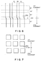
- Figure 6 is a partial plan view of the electrode part of another embodiment of the liquid crystal display device according to the invention.
- Figure 7 is a plan view showing an arrangement of display pixels of the liquid crystal display device of Figure 6.
- Figure 8 is a partial plan view of the electrode part of a liquid crystal display device of the prior art.
- Figure 9 is a plan view showing an arrangement of display pixels of the liquid crystal display device of Figure 8.
- Figure 10 is a partial plan view of the electrode part of another embodiment of the liquid crystal display device according to the invention.
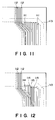
- Figure 11 is a partial plan view of an embodiment of the liquid crystal cell according to the invention.
- Figure 12 is a partial plan view of another embodiment of the liquid crystal cell according to the invention wherein the dummy pattern film is also used for another purpose.
- FIG. 1 is a partial plan view of the electrode part of an embodiment of the liquid crystal display device according to the present invention.
- transparent electrodes 11 constituting pixel electrodes are disposed with a spacing 12 (forming a spacing between pixels) so as to intersect with transparent electrodes 11' disposed with a spacing 12 on a counter substrate.
- a joint 14 between a first quadrant and a second quadrant is disposed at a spacing 12 and, at the joint 14, joint deviations 14x and 14y can appear in the x and y directions, respectively.
- each of the first and second quadrants is an area where printing is performed through a single exposure in a lithographic step.
- the first quadrant is exposed in a first time and the second quadrant is exposed in a second time.
- Figure 2 is a plan view showing arrangement of the resultant display pixels. As shown in Figures 1 and 2, a pixel spacing 12b including the joint 14 is different from an original pixel spacing 12a by the joint deviation 14x in the x direction but is not noticeable because it forms a non-display part.
- Figure 3 is a plan view of the electrode part of a liquid crystal display device of the prior art, wherein a joint 14 between the first and second quadrants is disposed on a transparent electrode 11.
- Figure 4 is a plan view showing an arrangement of the resultant pixels corresponding to Figure 3. As shown in Figures 3 and 4, a pixel width 11b including the joint 14 is different from an original pixel width 11a by a joint deviation 14x in the x direction, so that one line of the pixels provides a different luminance noticeable to human eyes.
- Two glass substrates each measuring 300 x 320 x t1.1 (mm) were respectively coated by sputtering with a 1000 A-thick transparent electrode (ITO) film, which was then patterned into stripe electrodes by photolithography.
- ITO transparent electrode
- the exposure was performed in four divisions by an exposure apparatus ("MPA-1500", mfd. by Canon K.K.) so as to provide a joint between pixels.
- the pattern of the stripe electrodes is shown in Figure 1.
- Each transparent electrode 11 was formed in a width of 230 ⁇ m with a spacing 12 of 12 ⁇ m.
- the joint deviations 14x and 14y were respectively 1.5 ⁇ m.
- Figure 5 is a partial plan view of the electrode part of another embodiment of the liquid crystal display device according to the present invention.
- a metal electrode 13 of a low electric resistance is disposed along each transparent electrode 11 constituting pixels.
- masking parts 33 for masking spacing between pixels on the counter substrate are formed also on the counter substrate, but they are omitted from showing for simplicity.
- a joint 14 between first and second quadrants is disposed at a spacing 12 between pixels.
- a joint deviation 14y in the y direction due to the masking parts 33 occurs as a positional deviation of pixels between the first and second quadrants.
- the width 33a of the masking part 33 is larger than the sum of a pixel spacing 12'a on the counter substrate and the joint deviation 14y in the y direction, there results in no change in actual display panel size nor does appear a joint in display pixels, so that the joint is not noticed.
- a liquid crystal device as shown in Figure 5 was prepared as follows. Two glass substrates each measuring 300 x 320 x t1.1 (mm) were respectively provided with 1200 ⁇ -thick stripe transparent electrodes in the same manner as in Example 1 and then further coated by sputtering with a 3000 ⁇ -thick Mo metal electrode, which was then formed into a pattern as shown in Figure 5 through a similar lithographic step as in the patterning of the transparent electrodes.
- the transparent electrodes 11 and 11' were formed in a width of 220 ⁇ m
- the metal electrodes 13 and 13' (not shown) were formed in a width of 20 ⁇ m
- the metal masking parts 33 and 33' (not shown) were formed in a width of 30 ⁇ m
- each pixel spacing was set to 10 ⁇ m.
- the joint deviation 14x and 14y were respectively 1.2 ⁇ m.
- a joint for forming a group of stripe electrodes in a direction parallel to the stripe electrodes at a non-display part including a spacing between pixels on the same substrate and an opaque metal member, it is possible to prevent an adverse effect of a mechanical joint deviation from occurring in a display by liquid crystal drive.
- the region of the opaque metal members may be included in the non-display part for obviating the adverse effect of the joint deviation.
- FIG. 6 is a partial plan view of the electrode part of an embodiment of the liquid crystal display device according to the present invention.
- transparent electrodes 61 constituting pixel electrodes are disposed with a spacing 62 (forming a spacing between pixels) so as to intersect with transparent electrodes 61' disposed with a spacing 62 on a counter substrate.
- a joint 64 between a first quadrant and a second quadrant is disposed at a spacing 62 on the counter substrate and, at the joint 64, a joint deviation 64a is present.
- each of the first and second quadrants is an area where printing is performed through a single exposure in a lithographic step.
- the first quadrant is exposed in a first time and the second quadrant is exposed in a second time.
- Figure 7 is a plan view showing arrangement of the resultant display pixels. As shown in Figures 6 and 7, the pixels in the first quadrant and the pixels in the second quadrant are deviated from each other by a joint deviation 64a at the joint 64, but the joint deviation is not noticeable because it is present in a non-display part.
- Figure 8 is a plan view of the electrode part of a liquid crystal display device of the prior art, wherein a joint 64 between the first and second quadrants is disposed in superposition of a transparent electrode 61' on the counter substrate.
- Figure 9 is a plan view showing an arrangement of the resultant pixels corresponding to Figure 8. As shown in Figures 8 and 9, a joint deviation 64a appears at pixels on the joint 64, so that it is noticeable to human eyes.
- the joint is disposed in alignment with a pixel spacing on the counter substrate.
- metal electrodes are disposed in addition to transparent electrodes, a similar effect is obtained also when a joint is disposed in alignment with a non-display part including a pixel spacing and a metal electrode on the counter substrate.
- Two glass substrates each measuring 300 x 320 x t1.1 (mm) were respectively coated by sputtering with a 1000 ⁇ -thick transparent electrode (ITO) film, which was then patterned into stripe electrodes by photolithography.
- the exposure was performed in four divisions by an exposure apparatus ("MPA-1500", mfd. by Canon K.K.) so as to provide a pattern of the stripe electrodes as shown in Figure 6.
- Each transparent electrode 61 was formed in a width of 200 ⁇ m with a spacing 12 of 20 ⁇ m.
- the joint deviation 64a was 2.0 ⁇ m.
- Figure 10 is a partial plan view of the electrode part of another embodiment of the liquid crystal display device according to the present invention.
- metal electrodes 63 and 63' of a low electric resistance are disposed along transparent electrodes 61 and 61', respectively, constituting pixels.
- a joint 64a formed at a joint between the first and second quadrants is in alignment with a metal electrode 63' (i.e., a non-display part) and is not noticeable.
- a liquid crystal device as shown in Figure 10 was prepared as follows. Two glass substrates each measuring 300 x 320 x t1.1 (mm) were respectively provided with 1200 ⁇ -thick stripe transparent electrodes in the same manner as in Example 3 and then further coated by sputtering with a 2000 ⁇ -thick A1 metal electrode, which was then formed into a pattern as shown in Figure 10 through a similar lithographic step as in the patterning of the transparent electrodes.
- the transparent electrodes 61 and 61' were formed in a width of 250 ⁇ m
- the metal electrodes 63 and 63' were formed in a width of 30 ⁇ m
- each pixel spacing 62 was set to 10 ⁇ m.
- the joint deviation 64a was 1.5 ⁇ m.
- a liquid crystal display device was formed by applying the above-treated two substrates so that the joint on one substrate was aligned with a metal electrode on the other substrate and vice versa. When the device was driven, the joints as a result of the four part division were not noticeable at all.
- the regions of the opaque metal electrodes may be included in the non-display region.
- the liquid crystal may preferably be a chiral smectic liquid crystal showing ferroelectricity.
- Figure 11 is a partial plan view of a liquid crystal cell according to an embodiment of the present invention.
- the liquid crystal cell includes pattern electrodes 112 for image display and dummy pattern films 111 for aiding the progress of a liquid crystal along them within a seal area 113.
- a liquid crystal injected through an injection port proceeds between a narrow path between image display pattern electrodes 112 left after etching. At this time, the liquid crystal proceeds at an identical speed also between the dummy pattern films up to a corner near the seal 113 under similar conditions as in the image display area.
- Figure 12 is a partial plan view of a liquid crystal cell according to another embodiment of the present invention.
- a dummy pattern film for aiding the liquid crystal injection is also used for another purpose.
- the cell includes image display pattern electrodes 112 and dummy pattern films 114 for aiding the liquid crystal injection within the seal area 113.
- the dummy pattern films 114 extends up to the seal area 113, whereby they also function to provide a uniform cell gap which is liable to be affected by the display pattern electrode thickness.
- the liquid crystal cell also includes dummy pattern films 115 which have a narrower width than the display pattern electrodes 112 and can be disposed in a higher density the in the display area. This is effective in preventing movement of a ferroelectric chiral smectic liquid crystal which is liable to move at the time of reheating after the injection and also in preventing the occurrence of a void caused by injection failure.
- the dummy pattern film may generally be of a similar material as a transparent image display pattern electrode or an opaque metal member but can be in a different shape as far as it shows the required effect of promoting the liquid crystal injection.
- a liquid crystal can be satisfactorily injected up to a part where the liquid crystal is not readily filled, so that it is possible to shorten the time required for liquid crystal injection into a cell of an identical volume, thus enhancing the capacity of the production apparatus.
- a liquid crystal device is constituted by a pair of oppositely spaced substrate each having on its opposite surface a group of stripe electrodes disposed to intersect with those disposed on the other substrate, and a liquid crystal disposed between the substrates so as to be driven by a voltage applied through the stripe electrodes.
- the group of stripe electrodes on at least one of the pair of substrates are formed through a lithographic step including dividing the stripe electrodes into at least two divisions at a line parallel (or perpendicular) to the extension of the stripe electrodes, and repeating a pattern exposure for each division of the stripe electrodes so as to dispose a joint between the divisions of the stripe electrodes at a non-display part including a spacing between two stripe electrode on the same substrate (or at a part in alignment with a non-display part including a spacing between two stripe electrodes on the opposite substrate).
- the liquid crystal device is provided with a dummy electrode pattern for promoting the liquid crystal injection.
Landscapes
- Physics & Mathematics (AREA)
- Nonlinear Science (AREA)
- Mathematical Physics (AREA)
- Chemical & Material Sciences (AREA)
- Crystallography & Structural Chemistry (AREA)
- General Physics & Mathematics (AREA)
- Optics & Photonics (AREA)
- Geometry (AREA)
- Liquid Crystal (AREA)
Priority Applications (1)
| Application Number | Priority Date | Filing Date | Title |
|---|---|---|---|
| EP95113126A EP0687936B1 (de) | 1991-10-07 | 1992-10-06 | Flüssigkristall-Anzeigevorrichtung und Verfahren zum Injizieren des Flüssigkristalls |
Applications Claiming Priority (6)
| Application Number | Priority Date | Filing Date | Title |
|---|---|---|---|
| JP28543691A JPH05100235A (ja) | 1991-10-07 | 1991-10-07 | 強誘電液晶の注入方法 |
| JP285436/91 | 1991-10-07 | ||
| JP29188491A JP2869828B2 (ja) | 1991-10-14 | 1991-10-14 | 液晶表示素子 |
| JP291885/91 | 1991-10-14 | ||
| JP3291885A JP2869829B2 (ja) | 1991-10-14 | 1991-10-14 | 液晶表示素子 |
| JP291884/91 | 1991-10-14 |
Related Child Applications (2)
| Application Number | Title | Priority Date | Filing Date |
|---|---|---|---|
| EP95113126.7 Division-Into | 1992-10-06 | ||
| EP95113126A Division EP0687936B1 (de) | 1991-10-07 | 1992-10-06 | Flüssigkristall-Anzeigevorrichtung und Verfahren zum Injizieren des Flüssigkristalls |
Publications (3)
| Publication Number | Publication Date |
|---|---|
| EP0536680A2 true EP0536680A2 (de) | 1993-04-14 |
| EP0536680A3 EP0536680A3 (en) | 1993-06-16 |
| EP0536680B1 EP0536680B1 (de) | 1997-01-02 |
Family
ID=27337175
Family Applications (2)
| Application Number | Title | Priority Date | Filing Date |
|---|---|---|---|
| EP92117005A Expired - Lifetime EP0536680B1 (de) | 1991-10-07 | 1992-10-06 | Flüssigkristallvorrichtung und Verfahren zum Einfüllen des Flüssigkristalls |
| EP95113126A Expired - Lifetime EP0687936B1 (de) | 1991-10-07 | 1992-10-06 | Flüssigkristall-Anzeigevorrichtung und Verfahren zum Injizieren des Flüssigkristalls |
Family Applications After (1)
| Application Number | Title | Priority Date | Filing Date |
|---|---|---|---|
| EP95113126A Expired - Lifetime EP0687936B1 (de) | 1991-10-07 | 1992-10-06 | Flüssigkristall-Anzeigevorrichtung und Verfahren zum Injizieren des Flüssigkristalls |
Country Status (4)
| Country | Link |
|---|---|
| US (2) | US5285300A (de) |
| EP (2) | EP0536680B1 (de) |
| AT (2) | ATE147169T1 (de) |
| DE (2) | DE69216348T2 (de) |
Cited By (1)
| Publication number | Priority date | Publication date | Assignee | Title |
|---|---|---|---|---|
| US6927825B1 (en) * | 1999-05-14 | 2005-08-09 | Sanyo Electric Co., Ltd. | Liquid crystal display using liquid crystal with bend alignment and driving method thereof |
Families Citing this family (34)
| Publication number | Priority date | Publication date | Assignee | Title |
|---|---|---|---|---|
| US5467209A (en) * | 1992-01-24 | 1995-11-14 | Canon Kabushiki Kaisha | Ferroelectric liquid crystal device with particular layer thicknesses at non-pixel portions and pixel portions |
| JP2704809B2 (ja) * | 1992-05-11 | 1998-01-26 | キヤノン株式会社 | 強誘電性液晶の注入方法 |
| JP2814171B2 (ja) * | 1992-08-19 | 1998-10-22 | キヤノン株式会社 | 液晶パネルの製造方法 |
| US5546998A (en) * | 1992-12-25 | 1996-08-20 | Canon Kabushiki Kaisha | Apparatus for vacuum injecting liquid crystal |
| JP2824819B2 (ja) * | 1992-12-25 | 1998-11-18 | キヤノン株式会社 | 液晶注入方法及び注入装置 |
| JP3086606B2 (ja) * | 1994-11-14 | 2000-09-11 | シャープ株式会社 | 液晶表示装置 |
| KR100416461B1 (ko) * | 1994-12-01 | 2004-04-28 | 코닌클리케 필립스 일렉트로닉스 엔.브이. | 더미전극을갖는디스플레이장치 |
| US6683594B1 (en) * | 1995-04-20 | 2004-01-27 | Canon Kabushiki Kaisha | Display apparatus and assembly of its driving circuit |
| US6169530B1 (en) * | 1995-04-20 | 2001-01-02 | Canon Kabushiki Kaisha | Display apparatus and assembly of its driving circuit |
| US5751391A (en) * | 1995-04-27 | 1998-05-12 | Canon Kabushiki Kaisha | Liquid crystal device with elongated projection height smaller than liquid crystal thickness and process for producing same |
| JP3296719B2 (ja) * | 1995-07-14 | 2002-07-02 | キヤノン株式会社 | カラー液晶表示素子及び該カラー液晶表示素子の製造方法 |
| JP3737176B2 (ja) * | 1995-12-21 | 2006-01-18 | 株式会社半導体エネルギー研究所 | 液晶表示装置 |
| US6320639B1 (en) | 1996-03-11 | 2001-11-20 | Canon Kabushiki Kaisha | Liquid crystal device and process for production thereof |
| JP3866815B2 (ja) * | 1996-03-27 | 2007-01-10 | セイコーエプソン株式会社 | 液晶パネル用基板、その製造方法、液晶装置及び電子機器 |
| KR100188110B1 (ko) * | 1996-04-10 | 1999-06-01 | 김광호 | 액정 표시 장치 |
| US5943108A (en) * | 1996-07-12 | 1999-08-24 | Canon Kabushiki Kaisha | Matrix type liquid crystal display with substrate having blue filter for masking at least 75% of total planar area of auxiliary electrodes |
| KR100205382B1 (ko) * | 1996-07-22 | 1999-07-01 | 구자홍 | 액정 표시 장치 |
| US5982470A (en) * | 1996-08-29 | 1999-11-09 | Sharp Kabushiki Kaisha | Liquid crystal display device having dummy electrodes with interleave ratio same on all sides |
| KR100228282B1 (ko) * | 1996-09-17 | 1999-11-01 | 윤종용 | 액정 표시 장치 |
| US6184962B1 (en) | 1997-03-05 | 2001-02-06 | Canon Kabushiki Kaisha | Liquid crystal display device with visible peripheral non-display region having masking sub-electrodes |
| US6271907B1 (en) | 1997-09-14 | 2001-08-07 | Canon Kabushiki Kaisha | Color liquid crystal device having injection port parallel to the stripe electrodes on the substrate with color filter and flattening film and the other substrate free from color filter and flattening film protruded |
| TW507091B (en) * | 1997-10-30 | 2002-10-21 | Matsushita Electric Industrial Co Ltd | Method of manufacturing liquid crystal display devices |
| KR100304261B1 (ko) * | 1999-04-16 | 2001-09-26 | 윤종용 | 테이프 캐리어 패키지, 그를 포함한 액정표시패널 어셈블리,그를 채용한 액정표시장치 및 이들의 조립 방법 |
| US7339568B2 (en) * | 1999-04-16 | 2008-03-04 | Samsung Electronics Co., Ltd. | Signal transmission film and a liquid crystal display panel having the same |
| JP3614050B2 (ja) * | 1999-09-20 | 2005-01-26 | セイコーエプソン株式会社 | 導体パターンの検査方法及び電気光学装置 |
| JP3617458B2 (ja) * | 2000-02-18 | 2005-02-02 | セイコーエプソン株式会社 | 表示装置用基板、液晶装置及び電子機器 |
| TWI299099B (en) * | 2000-03-30 | 2008-07-21 | Sharp Kk | Active matrix type liquid crystal display apparatus |
| KR100381868B1 (ko) * | 2000-11-29 | 2003-05-01 | 삼성전자주식회사 | 액정 표시 장치 및 그에 사용하는 기판 |
| KR100825093B1 (ko) * | 2001-09-27 | 2008-04-25 | 삼성전자주식회사 | 액정 표시 장치 |
| KR100450701B1 (ko) * | 2001-12-28 | 2004-10-01 | 엘지.필립스 엘시디 주식회사 | 액정표시장치용 어레이기판과 그 제조방법 |
| JP4169992B2 (ja) * | 2002-02-27 | 2008-10-22 | シャープ株式会社 | 液晶表示装置及びその駆動方法 |
| KR100870666B1 (ko) * | 2002-09-04 | 2008-11-26 | 엘지디스플레이 주식회사 | 액정 표시 장치 및 그 제조 방법 |
| TWI420214B (zh) * | 2010-05-06 | 2013-12-21 | Au Optronics Corp | 液晶顯示面板 |
| CN111613606B (zh) * | 2019-02-22 | 2022-05-10 | 群创光电股份有限公司 | 显示装置 |
Family Cites Families (16)
| Publication number | Priority date | Publication date | Assignee | Title |
|---|---|---|---|---|
| JPS5545073A (en) * | 1978-09-27 | 1980-03-29 | Seiko Epson Corp | Liquid crystal display panel |
| JPS57181580A (en) * | 1981-05-02 | 1982-11-09 | Sharp Kk | Matrix type liquid crystal display unit |
| DE3211408A1 (de) * | 1982-03-27 | 1983-09-29 | Vdo Adolf Schindling Ag, 6000 Frankfurt | Substrat |
| JPS59129832A (ja) * | 1983-01-18 | 1984-07-26 | Canon Inc | 光学変調装置 |
| US4660935A (en) * | 1984-02-21 | 1987-04-28 | Seiko Epson Corporation | Liquid crystal display device having electrodes shaped to compensate for positioning error |
| US4682858A (en) * | 1984-08-20 | 1987-07-28 | Canon Kabushiki Kaisha | Liquid crystal device having reduced-pressure region in communication with ferroelectric liquid crystal |
| JPH061313B2 (ja) * | 1985-02-06 | 1994-01-05 | シャープ株式会社 | 液晶表示装置 |
| JPH0727141B2 (ja) * | 1985-06-18 | 1995-03-29 | シチズン時計株式会社 | 液晶セルの電極構造 |
| JPH0769530B2 (ja) * | 1987-02-16 | 1995-07-31 | 株式会社日立製作所 | 液晶表示パネル及びその製造方法 |
| JPS63266427A (ja) * | 1987-04-24 | 1988-11-02 | Ricoh Co Ltd | 液晶表示素子 |
| US5000545A (en) * | 1987-05-28 | 1991-03-19 | Canon Kabushiki Kaisha | Liquid crystal device with metal electrode partially overlying transparent electrode |
| GB8812262D0 (en) * | 1988-05-24 | 1988-06-29 | Emi Plc Thorn | Display device |
| JPH02228629A (ja) * | 1989-02-28 | 1990-09-11 | Sharp Corp | 液晶表示装置 |
| DE3910418A1 (de) * | 1989-03-31 | 1990-10-04 | Licentia Gmbh | Anzeigevorrichtung |
| JP2673460B2 (ja) * | 1990-02-26 | 1997-11-05 | キヤノン株式会社 | 液晶表示素子 |
| JP2808480B2 (ja) * | 1990-07-18 | 1998-10-08 | キヤノン株式会社 | 液晶カラー表示素子用基板の製造方法 |
-
1992
- 1992-10-05 US US07/956,299 patent/US5285300A/en not_active Expired - Lifetime
- 1992-10-06 DE DE69216348T patent/DE69216348T2/de not_active Expired - Fee Related
- 1992-10-06 EP EP92117005A patent/EP0536680B1/de not_active Expired - Lifetime
- 1992-10-06 EP EP95113126A patent/EP0687936B1/de not_active Expired - Lifetime
- 1992-10-06 AT AT92117005T patent/ATE147169T1/de not_active IP Right Cessation
- 1992-10-06 AT AT95113126T patent/ATE209789T1/de active
- 1992-10-06 DE DE69232242T patent/DE69232242T2/de not_active Expired - Fee Related
-
1993
- 1993-11-04 US US08/145,641 patent/US5406398A/en not_active Expired - Lifetime
Cited By (1)
| Publication number | Priority date | Publication date | Assignee | Title |
|---|---|---|---|---|
| US6927825B1 (en) * | 1999-05-14 | 2005-08-09 | Sanyo Electric Co., Ltd. | Liquid crystal display using liquid crystal with bend alignment and driving method thereof |
Also Published As
| Publication number | Publication date |
|---|---|
| DE69216348T2 (de) | 1997-07-03 |
| US5406398A (en) | 1995-04-11 |
| DE69232242D1 (de) | 2002-01-10 |
| DE69216348D1 (de) | 1997-02-13 |
| DE69232242T2 (de) | 2002-06-13 |
| ATE147169T1 (de) | 1997-01-15 |
| EP0687936B1 (de) | 2001-11-28 |
| EP0687936A1 (de) | 1995-12-20 |
| EP0536680B1 (de) | 1997-01-02 |
| EP0536680A3 (en) | 1993-06-16 |
| ATE209789T1 (de) | 2001-12-15 |
| US5285300A (en) | 1994-02-08 |
Similar Documents
| Publication | Publication Date | Title |
|---|---|---|
| US5285300A (en) | Liquid crystal device | |
| KR100662780B1 (ko) | 테스트화소를 구비한 액정표시장치 및 이를 이용한 블랙 매트릭스를 제작하는 방법 | |
| US5828434A (en) | Liquid crystal display element with wall shaped spacers form between adjacent transparent electrodes and overlap portions of the light-shielding electrode films | |
| US4728176A (en) | Ferroelectric liquid crystal device with metallic auxiliary electrodes provided adjacent to the transparent electrodes | |
| DE102004052042B9 (de) | Flüssigkristall-Anzeigevorrichtung und Verfahren zum Herstellen derselben | |
| KR100362016B1 (ko) | 액정표시장치 | |
| US6798471B2 (en) | Liquid crystal display | |
| KR20010007523A (ko) | 멀티 도메인 액정 표시장치 | |
| EP1069462A1 (de) | Flüssigkristallanzeige und deren Herstellungverfahren | |
| US6972812B2 (en) | Liquid crystal display | |
| JP2000029014A (ja) | 液晶表示素子用カラーフィルタ基板及び液晶表示素子 | |
| EP0554091A1 (de) | Elektrooptische Farbflüssigkristallanordnung und deren Herstellungsverfahren | |
| JP2673739B2 (ja) | 液晶素子 | |
| DE68921910T2 (de) | Farbflüssigkristall-Anzeigevorrichtung und ihr Ansteuerungsverfahren. | |
| JPH06273735A (ja) | 液晶セル | |
| US5801802A (en) | Liquid crystal display panel with two alignment domains | |
| JP2551377B2 (ja) | 液晶ディスプレイ装置 | |
| US5706021A (en) | Liquid crystal display | |
| US6943860B2 (en) | Liquid crystal display | |
| JPH0829790A (ja) | 液晶表示装置 | |
| JP2869828B2 (ja) | 液晶表示素子 | |
| EP2083317A1 (de) | Flüssigkristallanzeige und Herstellungsverfahren dafür | |
| JPS6287936A (ja) | 液晶デイスプレ−用電極基板 | |
| JPH0682784A (ja) | 液晶パネルの製造方法 | |
| KR100315923B1 (ko) | 액정표시장치 |
Legal Events
| Date | Code | Title | Description |
|---|---|---|---|
| PUAI | Public reference made under article 153(3) epc to a published international application that has entered the european phase |
Free format text: ORIGINAL CODE: 0009012 |
|
| 17P | Request for examination filed |
Effective date: 19921006 |
|
| AK | Designated contracting states |
Kind code of ref document: A2 Designated state(s): AT BE CH DE DK ES FR GB GR IT LI LU NL PT SE |
|
| PUAL | Search report despatched |
Free format text: ORIGINAL CODE: 0009013 |
|
| AK | Designated contracting states |
Kind code of ref document: A3 Designated state(s): AT BE CH DE DK ES FR GB GR IT LI LU NL PT SE |
|
| 17Q | First examination report despatched |
Effective date: 19950220 |
|
| GRAG | Despatch of communication of intention to grant |
Free format text: ORIGINAL CODE: EPIDOS AGRA |
|
| GRAH | Despatch of communication of intention to grant a patent |
Free format text: ORIGINAL CODE: EPIDOS IGRA |
|
| GRAH | Despatch of communication of intention to grant a patent |
Free format text: ORIGINAL CODE: EPIDOS IGRA |
|
| GRAA | (expected) grant |
Free format text: ORIGINAL CODE: 0009210 |
|
| AK | Designated contracting states |
Kind code of ref document: B1 Designated state(s): AT BE CH DE DK ES FR GB GR IT LI LU NL PT SE |
|
| DX | Miscellaneous (deleted) | ||
| PG25 | Lapsed in a contracting state [announced via postgrant information from national office to epo] |
Ref country code: LI Effective date: 19970102 Ref country code: GR Free format text: LAPSE BECAUSE OF FAILURE TO SUBMIT A TRANSLATION OF THE DESCRIPTION OR TO PAY THE FEE WITHIN THE PRESCRIBED TIME-LIMIT Effective date: 19970102 Ref country code: ES Free format text: THE PATENT HAS BEEN ANNULLED BY A DECISION OF A NATIONAL AUTHORITY Effective date: 19970102 Ref country code: DK Effective date: 19970102 Ref country code: CH Effective date: 19970102 Ref country code: BE Effective date: 19970102 Ref country code: AT Effective date: 19970102 |
|
| REF | Corresponds to: |
Ref document number: 147169 Country of ref document: AT Date of ref document: 19970115 Kind code of ref document: T |
|
| REG | Reference to a national code |
Ref country code: CH Ref legal event code: EP |
|
| REF | Corresponds to: |
Ref document number: 69216348 Country of ref document: DE Date of ref document: 19970213 |
|
| ET | Fr: translation filed | ||
| ITF | It: translation for a ep patent filed | ||
| PG25 | Lapsed in a contracting state [announced via postgrant information from national office to epo] |
Ref country code: PT Effective date: 19970402 |
|
| REG | Reference to a national code |
Ref country code: CH Ref legal event code: PL |
|
| PG25 | Lapsed in a contracting state [announced via postgrant information from national office to epo] |
Ref country code: LU Free format text: LAPSE BECAUSE OF NON-PAYMENT OF DUE FEES Effective date: 19971006 |
|
| PLBE | No opposition filed within time limit |
Free format text: ORIGINAL CODE: 0009261 |
|
| 26N | No opposition filed | ||
| REG | Reference to a national code |
Ref country code: GB Ref legal event code: IF02 |
|
| PGFP | Annual fee paid to national office [announced via postgrant information from national office to epo] |
Ref country code: GB Payment date: 20021002 Year of fee payment: 11 |
|
| PGFP | Annual fee paid to national office [announced via postgrant information from national office to epo] |
Ref country code: SE Payment date: 20021004 Year of fee payment: 11 |
|
| PGFP | Annual fee paid to national office [announced via postgrant information from national office to epo] |
Ref country code: FR Payment date: 20021008 Year of fee payment: 11 |
|
| PGFP | Annual fee paid to national office [announced via postgrant information from national office to epo] |
Ref country code: DE Payment date: 20021011 Year of fee payment: 11 |
|
| PGFP | Annual fee paid to national office [announced via postgrant information from national office to epo] |
Ref country code: NL Payment date: 20021031 Year of fee payment: 11 |
|
| PG25 | Lapsed in a contracting state [announced via postgrant information from national office to epo] |
Ref country code: GB Free format text: LAPSE BECAUSE OF NON-PAYMENT OF DUE FEES Effective date: 20031006 |
|
| PG25 | Lapsed in a contracting state [announced via postgrant information from national office to epo] |
Ref country code: SE Free format text: LAPSE BECAUSE OF NON-PAYMENT OF DUE FEES Effective date: 20031007 |
|
| PG25 | Lapsed in a contracting state [announced via postgrant information from national office to epo] |
Ref country code: NL Free format text: LAPSE BECAUSE OF NON-PAYMENT OF DUE FEES Effective date: 20040501 Ref country code: DE Free format text: LAPSE BECAUSE OF NON-PAYMENT OF DUE FEES Effective date: 20040501 |
|
| GBPC | Gb: european patent ceased through non-payment of renewal fee |
Effective date: 20031006 |
|
| EUG | Se: european patent has lapsed | ||
| PG25 | Lapsed in a contracting state [announced via postgrant information from national office to epo] |
Ref country code: FR Free format text: LAPSE BECAUSE OF NON-PAYMENT OF DUE FEES Effective date: 20040630 |
|
| NLV4 | Nl: lapsed or anulled due to non-payment of the annual fee |
Effective date: 20040501 |
|
| REG | Reference to a national code |
Ref country code: FR Ref legal event code: ST |
|
| PG25 | Lapsed in a contracting state [announced via postgrant information from national office to epo] |
Ref country code: IT Free format text: LAPSE BECAUSE OF NON-PAYMENT OF DUE FEES;WARNING: LAPSES OF ITALIAN PATENTS WITH EFFECTIVE DATE BEFORE 2007 MAY HAVE OCCURRED AT ANY TIME BEFORE 2007. THE CORRECT EFFECTIVE DATE MAY BE DIFFERENT FROM THE ONE RECORDED. Effective date: 20051006 |