EP0534794B2 - Dispositif pour l'impression sur rubans - Google Patents
Dispositif pour l'impression sur rubans Download PDFInfo
- Publication number
- EP0534794B2 EP0534794B2 EP92308789A EP92308789A EP0534794B2 EP 0534794 B2 EP0534794 B2 EP 0534794B2 EP 92308789 A EP92308789 A EP 92308789A EP 92308789 A EP92308789 A EP 92308789A EP 0534794 B2 EP0534794 B2 EP 0534794B2
- Authority
- EP
- European Patent Office
- Prior art keywords
- characters
- tape
- symbols
- width
- printed
- Prior art date
- Legal status (The legal status is an assumption and is not a legal conclusion. Google has not performed a legal analysis and makes no representation as to the accuracy of the status listed.)
- Expired - Lifetime
Links
- 230000015654 memory Effects 0.000 claims description 23
- 230000002401 inhibitory effect Effects 0.000 claims description 2
- 230000008878 coupling Effects 0.000 claims 1
- 238000010168 coupling process Methods 0.000 claims 1
- 238000005859 coupling reaction Methods 0.000 claims 1
- 230000004308 accommodation Effects 0.000 description 12
- 238000000034 method Methods 0.000 description 8
- 239000002390 adhesive tape Substances 0.000 description 4
- 238000010438 heat treatment Methods 0.000 description 3
- 239000004973 liquid crystal related substance Substances 0.000 description 3
- 238000004804 winding Methods 0.000 description 3
- 238000006243 chemical reaction Methods 0.000 description 2
- 238000010586 diagram Methods 0.000 description 2
- 238000004886 process control Methods 0.000 description 1
- 230000004044 response Effects 0.000 description 1
Images


Classifications
-
- B—PERFORMING OPERATIONS; TRANSPORTING
- B41—PRINTING; LINING MACHINES; TYPEWRITERS; STAMPS
- B41J—TYPEWRITERS; SELECTIVE PRINTING MECHANISMS, i.e. MECHANISMS PRINTING OTHERWISE THAN FROM A FORME; CORRECTION OF TYPOGRAPHICAL ERRORS
- B41J2/00—Typewriters or selective printing mechanisms characterised by the printing or marking process for which they are designed
- B41J2/485—Typewriters or selective printing mechanisms characterised by the printing or marking process for which they are designed characterised by the process of building-up characters or image elements applicable to two or more kinds of printing or marking processes
- B41J2/505—Typewriters or selective printing mechanisms characterised by the printing or marking process for which they are designed characterised by the process of building-up characters or image elements applicable to two or more kinds of printing or marking processes from an assembly of identical printing elements
- B41J2/5056—Typewriters or selective printing mechanisms characterised by the printing or marking process for which they are designed characterised by the process of building-up characters or image elements applicable to two or more kinds of printing or marking processes from an assembly of identical printing elements using dot arrays providing selective dot disposition modes, e.g. different dot densities for high speed and high-quality printing, array line selections for multi-pass printing, or dot shifts for character inclination
- B41J2/5058—Typewriters or selective printing mechanisms characterised by the printing or marking process for which they are designed characterised by the process of building-up characters or image elements applicable to two or more kinds of printing or marking processes from an assembly of identical printing elements using dot arrays providing selective dot disposition modes, e.g. different dot densities for high speed and high-quality printing, array line selections for multi-pass printing, or dot shifts for character inclination locally, i.e. for single dots or for small areas of a character
-
- B—PERFORMING OPERATIONS; TRANSPORTING
- B41—PRINTING; LINING MACHINES; TYPEWRITERS; STAMPS
- B41J—TYPEWRITERS; SELECTIVE PRINTING MECHANISMS, i.e. MECHANISMS PRINTING OTHERWISE THAN FROM A FORME; CORRECTION OF TYPOGRAPHICAL ERRORS
- B41J3/00—Typewriters or selective printing or marking mechanisms characterised by the purpose for which they are constructed
- B41J3/407—Typewriters or selective printing or marking mechanisms characterised by the purpose for which they are constructed for marking on special material
- B41J3/4075—Tape printers; Label printers
Definitions
- the present invention relates to a printing device for printing images, such as characters/symbols, on a tape member.
- the present applicant proposed in the United States Patent No. 07/831,971 a printing device by which the print region on print tape having a width of about 10 mm is divided into two portions along a tape width direction to provide two print lines, and input char acters are printed on a desired print line by using a dot pattern having a small character size for printing characters to the two print lines.
- the printing device proposed by the present applicant In Japanese Patent Application HEI 3-91492 is arranged to print characters to 1 or 2 lines by using a relatively narrow print tape having a tape width of about 10 mm.
- a relatively narrow print tape having a tape width of about 10 mm.
- a tape printing device for printing characters/symbols on a tape member contained in a cassette when the cassette is coupled with the device, the cassette having tape width representation means for representing to the printing device the width of the tape member contained therein, the printing device comprising:
- the determining means may be arranged to determine said size by dividing the number of dots capable of being included in the width of the tape member by the number of lines of characters/symbols to be printed within the width, and by dividing the number of dots capable of being included in a line within the inputted length of the tape member by the number of characters/symbols to be printed within the inputted length.
- the determining means may alternatively be arranged to determine the size of the characters/symbols to be printed by determining a first size based upon the detected number of characters/symbols and a second size based upon the detected number of lines of characters/ symbols to be printed, and thereafter to base selection of the size of characters/symbols to be printed on said first and second sizes.
- the determining means may be arranged to determine said first size by dividing the number of dots capable of being included in a line within said inputted length of tape member by the detected number of characters/symbols and to determine said second size by dividing the number of dots capable of being included in the width of the tape member by the detected number of lines of characters/symbols to be printed.
- a memory may be provided for storing dot data corresponding to a plurality of sizes of the characters/symbols, and wherein the determining means selects one of the plurality of sizes as the size of characters/symbols to be printed.
- a character size to be printed may be determined in accordance with the tape width of a tape used as a print medium and the number of lines of inputted characters, and an optimum character size based on these print conditions may be automatically determined.
- Fig. 1 is a plan view of a printing device 1 embodying the present invention.
- the printing device 1 is capable of printing images such as a number of characters/symbols and the like on a plurality of lines of a tape, or a tape-form printing medium in the width direction thereof.
- a keyboard 3 is disposed on the front portion of the main body frame 2 of a printing device 1
- a print mechanism PM is disposed in the main body frame 2 behind (upper direction in the figure) the keyboard 3
- a liquid crystal display unit 22 capable of displaying characters and symbols is disposed behind (upper direction in the figure) the keyboard 3.
- the keyboard 3 includes character keys for inputting alphabet, or the like, numeral keys, symbol keys, a return key, non-conversion key, conversion key, print key for performing a print processing, font selection key for selecting a font of characters, tape feed key for feeding the tape 5, power supply key for tuning ON and OFF a power supply, and the like.
- the keyboard 3 includes a character size key for setting a character size, a print length key for setting the length of the tape 5 used when characters are printed, a cursor movement key for moving a cursor in the upward and downward directions and in the right and left directions within the display unit 22, and the like.
- the print mechanism PM includes a rectangular tape accommodation cassette CS detachably loaded thereto.
- the tape accommodation cassette CS includes a tape spool 6 around which the tape 5 having a width of about 24 mm and formed of a transparent film is wound; a ribbon supply spool 8 around which an ink ribbon 7 is wound; a winding spool 9 for winding the ink ribbon 7; a supply spool 11 around which a double-sided adhesive tape 10 having the same width as that of the tape 5 is wound with the releasable paper provided facing the outside; and a adhere roller 12 for adhering the print tape 5 with the double-sided adhesive tape 10.
- These spools and roller are rotatably mounted to the tape accommodation cassette CS.
- a thermal head 13 is vertically disposed at the position where the print tape 5 is placed on the ink ribbon 7.
- a platen roller 14 for pressing the print tape 5 and ink ribbon 7 against the thermal head 13, and a feed roller for pressing the print tape 5 and double- sided adhesive tape 10 against the adhere roller 12 are rotatably supported by a support member 16.
- the thermal head 13 includes a heating element group composed of 128 heating elements aligned in the width direction of the tape 5 thereon.
- a pair of projected pieces 17, 18 projecting downwardly are integrally defined to the bottom wall of the tape accommodation cassette CS so that the tape width of the tape 5 accommodated therein can be indicated by the presence or absence of these projected pieces 17, 18. More specifically, when both the projected pieces 17, 18 are provided with the tape accommodation cassette CS shown in Fig. 2, the tape 5 accommodated therein has a width of 24 mm.
- first and second sensors 20, 21 composed of a photo interrupter (refer to Fig. 3) are provided in the main body frame 2 to detect the projected pieces 17, 18 when the tape accommodation cassette is loaded.
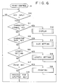
- control system of the printing device 1 is arranged as shown in the block diagram of Fig. 3.
- the key board 3 the first sensor 20, the second sensor 21, a liquid crystal display controller (LCDC) 23 having a display RAM for outputting display data to the liquid crystal display unit (LCD) 22, drive circuit 25 for driving the thermal head 13, and drive circuit 26 for driving the tape feed motor 24 are interconnected to the I/O interface 27 of a control unit C, respectively.
- LCDC liquid crystal display controller
- the control unit C includes a CPU 29, the I/O interface 27 connected to the CPU 29 through a bus such as a data bus 28, ROM (Read Only Memory) 30, CGROM (Character Generator ROM) 31 and RAM 40.
- ROM Read Only Memory
- CGROM Charge Generator ROM
- the ROM (as a program memory) 30 stores:
- the CGROM (as a pattern data memory) 31 stores dot pattern data corresponding to each of the plurality of character sizes (S1, S2, S3 ... Si) with respect to respective characters/symbols.
- a print length setting process is executed (S16).
- this length setting process first, "print length: 50 mm” is displayed, then "print length: 51 mm”, “print length: 52 mm”, “print length: 53 mm” ... up to “print length: 300 mm” are sequentially displayed with a pitch of 1 mm upon operating the cursor movement key. Therefore, a print length can be set by operating the return key in the state that a desired print length is displayed.
- the text data in the text memory 41 is searched, the number of lines M of the text data is stored in the memory 45, and the number of maximum characters N of the characters included in the respective lines is stored in the memory 46 (S32).
- the number of longitudinal dots td of characters to be printed on each line is determined by dividing the tape width Dd by the number of lines M (S33), and further the number of lateral dots yd of the characters to be printed is determined by dividing the print length Ld by the maximum number of characters N(S34).
- the item T1 indicating the first row of the number of longitudinal dots is set to the longitudinal pointer Tp (S35). If the number of longitudinal dots Tnd indicated by the longitudinal pointer Tp is greater than the number of longitudinal dots td determined base on the calculation (S36:No), the longitudinal pointer Tp is incremented by 1 (S37).
- the steps S36 through S38 are repeated. Note that if the character size is too small, the printed character/symbol is difficult to read, or the quality of printed characters/symbols becomes quite low.
- il is examined whether the number of dots is greater than a predetermined value, i.e., Er. If the number of longitudinal dots Tnd indicated by the longitudinal pointer Tp is equal to or less than the number of longitudinal dots td (S36: Yes), the value of the longitudinal pointer Tp is set to the lateral pointer Yp (S39). For example, as shown in Fig. 4, when the longitudinal pointer Tp indicates the fifth row of the table 19 in Fig. 4, in this case "5" has been set to the longitudinal pointer Tp, "5" is set to the lateral pointer Yp which indicates the row of the lateral dots in the table 19.
- the lateral pointer Yp is incremented by 1 (S41). If the number of dots indicated by the lateral pointer Yp is not error data Er (S42:No), the steps S40 through S42 are repeated. If the number of lateral dots Ynd indicated by the lateral pointer Yp is equal to or less than the number of lateral dots yd (S42:Yes), a character size Sn corresponding to the number of lateral dots indicated by the lateral pointer Yp is determined as a printing character size and stored in the character size memory 42.
- the text data is developed to dot pattern data by using the dot pattern corresponding to the determined character size Sn in the print buffer 51 (S44), and a print processing is executed onto the tape 5 with use of the thermal head 13 based on the dot pattern data in the print buffer 51 (S45).
- a print processing is executed onto the tape 5 with use of the thermal head 13 based on the dot pattern data in the print buffer 51 (S45).
- characters are to be printed onto the tape 5 having a tape width of 24 mm on one line as shown in Fig. 8, the characters are printed at substantially the maximum character size based on the number of line "1" and tape width "24".
- Fig. 9 when the characters are to be printed on two fines, they are printed by a character size suitable for a print on the two lines based on the number of lines "2" and tape width "24".
- the characters when the characters are to be printed on three lines, they are printed by a character size suitable for a print on the three lines (refer to Fig. 10), and when the characters are to be printed on four lines, they are printed by a character size suitable for a print on the four lines (refer to Fig. 11).
- a character size to be printed is determined in accordance with the tape width of the tape 5 used as a print medium, the number of lines of input characters and a print length, an optimum character size based on these print conditions can be automatically determined.
- each dot pattern data includes the blank space between characters and lines, thereby printed characters/symbols are optimumly soaced with each other.
Claims (10)
- Dispositif d'impression sur ruban (1) pour imprimer des caractères/symboles sur un élément formant ruban (5) contenu dans une cassette (CS) lorsque la cassette est reliée au dispositif, la cassette (CS) ayant des moyens de représentation de largeur de ruban (17, 18) pour faire observer au dispositif d'impression (1) la largeur de l'élément formant ruban (5) contenu à l'intérieur, le dispositif d'impression comprenant :des moyens de détection (20, 21) pour détecter les moyens de représentation de largeur de ruban (17, 18) d'une cassette (CS), lorsque la cassette est reliée au dispositif, pour la détermination de la largeur de l'élément formant ruban (5) contenu dans la cassette ;des moyens (3) pour entrer une longueur de l'élément formant ruban (5), longueur dans laquelle les caractères/symboles doivent être imprimés ;des premiers moyens de détection pour détecter le nombre (N) de caractères/symboles à imprimer dans une ligne dans ladite longueur de l'élément formant ruban ;des seconds moyens de détection pour détecter le nombre (M) de lignes de caractères/symboles à imprimer dans la largeur de l'élément formant ruban ; etdes moyens de détermination conçus pour déterminer la taille (Sn) des caractères/symboles à imprimer en basant la détermination sur la totalité :de la longueur entrée de l'élément formant ruban (5),du nombre de caractères/symboles détectés par lesdits premiers moyens de détection,de la largeur de l'élément formant ruban, etdu nombre de lignes détectées par lesdits seconds moyens de détection.
- Dispositif d'impression selon la revendication 1, dans lequel lesdits moyens de détermination sont conçus pour déterminer ladite taille (Sn) en divisant la nombre de points (Dd) capables d'être inclus dans la largeur de l'élément formant ruban (5) par la nombre (M) de lignes de caractères/symboles à imprimer dans la largeur, et en divisant le nombre (Ld) de points capables d'être inclus dans une ligne dans la longueur entrée de l'élément formant ruban (5) par le nombre (N) de caractères/symboles à imprimer dans la longueur entrée.
- Dispositif d'impression selon la revendication 1, dans lequel lesdits moyens de détermination sont conçus pour déterminer la taille (Sn) des caractères/symboles à imprimer en déterminant une première taille (yd) sur la base du nombre détecté (N) de caractères/symbole et une seconde taille (td) sur la base du nombre détecté (M) de lignes de caractères/symboles à imprimer, et après cela pour baser la sélection de la taille (Sn) de caractères/symboles à imprimer sur lesdites première et seconde tailles.
- Dispositif d'impression selon la revendication 3, dans lequel lesdits moyens de détermination sont conçus pour déterminer ladite première taille (yd) en divisant le nombre (Ld) de points capables d'étre inclus dans une ligne dans ladite longueur entrée d'élément formant ruban (5) par le nombre détecté (N) de caractères/symboles,
- Dispositif d'impression selon la revendication 3 ou la revendication 4, dans lequel lesdits moyens de détermination sont. conçus pour déterminer ladite seconde taille (td) en divisant 1e nombre (Dd) de points capables d'être inclus dans la largeur de l'élément formant ruban (S) par le nombre détecté (M) de lignes de caractères/symboles à imprimer.
- Dispositif d'impression selon l'une quelconque des revendications précédentes, comprenant, de plus, des moyens formant mémoire (31) pour stocker des données de points correspondant à une pluralité de tailles différentes (Sl-Si) de caractères/symboles, et dans lequel lesdits moyens de détermination sont conçus pour sélectionner une taille particulière (Sn) parmi ladite pluralité de tailles en tant que taille des caractères/symboles à imprimer.
- Dispositif d'impression selon l'une quelconque des revendications précédentes, comprenant, de plus, des moyens pour inhiber l'impression lorsque la taille (Er) déterminée par lesdits moyens de détermination est plus petite qu'une taille prédéterminée (Si).
- Dispositif d'impression selon l'une quelconque des revendications précédente, dans lequel lesdits moyens de détection comprennent au moins un détecteur (20, 21) pour détecter, lorsque la cassette (CS) est reliée au dispositif d'impression (1), l'existence d'au moins une protection particulière (17, 18), disposée sur un élément formant boítier de la cassette, de façon à détecter que l'élément formant ruban contenu dans la cassette a une première largeur prédéterminée lorsque l'existence de ladite au moins une partie en saillie est détectée, et de façon à détecter que l'élément formant ruban a une seconde largeur prédéterminée lorsque l'existence de ladite au moins une partie en saillie n'est pas détectée.
- Combinaison d'un dispositif d'impression selon l'une quelconque des revendications précédentes avec une cassette (CS) contenant ledit élément formant ruban (5) et pour relier au dispositif d'impression (1), ladite cassette comprenant lesdits moyens de représentation de largeur de ruban (17, 18) pour faire observer au dispositif d'impression la largeur de l'élément formant ruban contenu dans la cassette.
- Combinaison selon la revendication 9, dans laquelle ladite cassette (CS) comprend un élément formant boítier, et dans laquelle lesdits moyens de représentation de largeur de bande comprennent au moins une partie en saillie (17, 18) sur ledit élément formant boítier pour faire observer que la largeur de l'élément formant ruban (5) contenu dans la cassette est d'une largeur prédéterminée.
Priority Applications (1)
| Application Number | Priority Date | Filing Date | Title |
|---|---|---|---|
| DE19929218594 DE9218594U1 (de) | 1991-09-25 | 1992-09-25 | Banddrucker |
Applications Claiming Priority (3)
| Application Number | Priority Date | Filing Date | Title |
|---|---|---|---|
| JP274852/91 | 1991-09-25 | ||
| JP3274852A JP2556224B2 (ja) | 1991-09-25 | 1991-09-25 | テープ印字装置 |
| JP27485291 | 1991-09-25 |
Publications (4)
| Publication Number | Publication Date |
|---|---|
| EP0534794A2 EP0534794A2 (fr) | 1993-03-31 |
| EP0534794A3 EP0534794A3 (en) | 1993-04-21 |
| EP0534794B1 EP0534794B1 (fr) | 1996-01-10 |
| EP0534794B2 true EP0534794B2 (fr) | 2001-08-22 |
Family
ID=17547478
Family Applications (1)
| Application Number | Title | Priority Date | Filing Date |
|---|---|---|---|
| EP92308789A Expired - Lifetime EP0534794B2 (fr) | 1991-09-25 | 1992-09-25 | Dispositif pour l'impression sur rubans |
Country Status (4)
| Country | Link |
|---|---|
| US (1) | US5314256A (fr) |
| EP (1) | EP0534794B2 (fr) |
| JP (1) | JP2556224B2 (fr) |
| DE (1) | DE69207538T3 (fr) |
Families Citing this family (40)
| Publication number | Priority date | Publication date | Assignee | Title |
|---|---|---|---|---|
| JP2893499B2 (ja) * | 1992-10-13 | 1999-05-24 | セイコーエプソン株式会社 | テープカートリッジおよびテープライタ |
| JP3212039B2 (ja) * | 1992-02-21 | 2001-09-25 | ブラザー工業株式会社 | テープ印字装置 |
| JP2556238B2 (ja) * | 1992-04-30 | 1996-11-20 | ブラザー工業株式会社 | テープ印字装置 |
| GB9212439D0 (en) * | 1992-06-11 | 1992-07-22 | Esselte Dymo Nv | Label printing apparatus |
| US5595450A (en) * | 1992-06-11 | 1997-01-21 | Esselte N.V. | Label printing apparatus with display |
| CA2107759A1 (fr) * | 1992-10-06 | 1994-04-07 | Masahiko Nunokawa | Dispositif d'impression de bande |
| US5934812A (en) * | 1992-10-06 | 1999-08-10 | Seiko Epson Corp. | Tape printing device and tape cartridge used therein |
| CA2107746A1 (fr) * | 1992-10-06 | 1994-04-07 | Masahiko Nunokawa | Dispositif d'impression a ruban et cartouche de ruban pour ce dispositif |
| JP2822120B2 (ja) * | 1992-11-05 | 1998-11-11 | セイコーエプソン株式会社 | 印字装置 |
| US6092947A (en) * | 1992-10-06 | 2000-07-25 | Seiko Epson Corporation & King Jim Co., Ltd. | Tape printing device |
| US5836061A (en) * | 1997-07-12 | 1998-11-17 | Honda Giken Kogyo Kabushiki Kaisha | Cable end anchoring nipple and methods of constructing and utilizing same |
| US5819011A (en) * | 1992-12-30 | 1998-10-06 | International Business Machines Corporation | Media boundary traversal method and apparatus |
| JP2768192B2 (ja) * | 1993-01-07 | 1998-06-25 | ブラザー工業株式会社 | テープ印字装置 |
| JP3378622B2 (ja) * | 1993-09-21 | 2003-02-17 | ブラザー工業株式会社 | テープ印刷装置 |
| JPH07125374A (ja) * | 1993-11-02 | 1995-05-16 | King Jim Co Ltd | レイアウト表示装置 |
| JP3130194B2 (ja) * | 1993-11-09 | 2001-01-31 | 株式会社キングジム | テープ印刷装置及び方法 |
| JP2910817B2 (ja) * | 1993-12-01 | 1999-06-23 | ブラザー工業株式会社 | テープ印刷装置 |
| JP3111442B2 (ja) * | 1993-12-14 | 2000-11-20 | ブラザー工業株式会社 | 文書処理装置 |
| US5675708A (en) * | 1993-12-22 | 1997-10-07 | International Business Machines Corporation | Audio media boundary traversal method and apparatus |
| US5503482A (en) * | 1993-12-29 | 1996-04-02 | Brother Kogyo Kabushiki Kaisha | Tape printing apparatus |
| US5496119A (en) * | 1993-12-29 | 1996-03-05 | Brother Kogyo Kabushiki Kaisha | Tape printer having a display |
| US5524995A (en) * | 1994-11-14 | 1996-06-11 | Pitney Bowes, Inc. | Apparatus and method for detecting the position of envelopes in a mailing machine |
| TW395331U (en) * | 1995-12-28 | 2000-06-21 | Seiko Epson Corp | Electronic machine |
| US6226094B1 (en) * | 1996-01-05 | 2001-05-01 | King Jim Co., Ltd. | Apparatus and method for processing character information |
| EP0798539B1 (fr) * | 1996-03-29 | 2004-05-19 | Sanyo Electric Co. Ltd | Dispositif de navigation |
| JP3549343B2 (ja) * | 1996-11-15 | 2004-08-04 | 株式会社キングジム | 文字情報処理装置 |
| US6234694B1 (en) * | 1997-07-29 | 2001-05-22 | Ascom Hasler Mailing Systems Inc. | Media control to eliminate printing images beyond the media boundaries |
| EP0933221B1 (fr) | 1998-02-02 | 2006-06-28 | Canon Kabushiki Kaisha | Appareil d'enregistrement, méthode d'enregistrement, et moyen de stockage |
| JP3948157B2 (ja) | 1999-03-31 | 2007-07-25 | ブラザー工業株式会社 | ラベルライター用テープ及びラベルライター |
| JP2002149152A (ja) * | 2000-11-10 | 2002-05-24 | Fujitsu Ltd | 画像表示制御装置 |
| WO2005086882A2 (fr) | 2004-03-10 | 2005-09-22 | Kroy Llc | Dispositif d'impression sur bande et procede d'impression |
| JP4862271B2 (ja) * | 2005-03-31 | 2012-01-25 | ブラザー工業株式会社 | ラベル作成装置 |
| JP4811282B2 (ja) * | 2007-01-25 | 2011-11-09 | ブラザー工業株式会社 | テープ印刷装置及びテープ印刷プログラム |
| JP4325688B2 (ja) | 2007-02-27 | 2009-09-02 | ブラザー工業株式会社 | 印刷装置 |
| US9333777B2 (en) | 2013-07-16 | 2016-05-10 | Esselte Ipr Ab | Label printer |
| USD753585S1 (en) | 2014-05-08 | 2016-04-12 | Esselte Ipr Ab | Battery module for a printer |
| USD763350S1 (en) | 2014-05-08 | 2016-08-09 | Esselte Ipr Ab | Cartridge for printer |
| USD775274S1 (en) | 2014-05-08 | 2016-12-27 | Esselte Ipr Ab | Printer |
| JP6434875B2 (ja) * | 2015-08-11 | 2018-12-05 | セイコーエプソン株式会社 | 情報処理装置、情報処理装置における選択肢設定方法およびプログラム |
| US10124600B2 (en) * | 2016-09-27 | 2018-11-13 | Casio Computer Co., Ltd. | Printing device, printing method, and nonvolatile computer-readable recording medium |
Citations (5)
| Publication number | Priority date | Publication date | Assignee | Title |
|---|---|---|---|---|
| JPS60234856A (ja) † | 1984-05-09 | 1985-11-21 | Canon Inc | 記録装置 |
| US4651288A (en) † | 1983-11-11 | 1987-03-17 | Olympia Werke Ag | Method and apparatus for filling out a form by a machine |
| US4814894A (en) † | 1984-04-16 | 1989-03-21 | Canon Kabushiki Kaisha | Image transmitting system having density selection |
| JPH0372461U (fr) † | 1989-11-20 | 1991-07-22 | ||
| EP0497352A2 (fr) † | 1991-01-31 | 1992-08-05 | Casio Computer Co., Ltd. | Imprimante pour bande |
Family Cites Families (31)
| Publication number | Priority date | Publication date | Assignee | Title |
|---|---|---|---|---|
| EP0089190B1 (fr) * | 1982-03-11 | 1989-06-14 | Kabushiki Kaisha Ishida Koki Seisakusho | Production d'étiquettes descriptives pour des articles différents |
| JPS5931173A (ja) * | 1982-08-17 | 1984-02-20 | Sato :Kk | 連続札印字装置 |
| JPS6014292A (ja) * | 1983-07-06 | 1985-01-24 | 株式会社東芝 | 文書作成装置 |
| JPS60109892A (ja) * | 1983-11-18 | 1985-06-15 | Brother Ind Ltd | 電子式タイプライタ |
| FR2566327B1 (fr) * | 1984-06-25 | 1989-06-02 | Epson Corp | Imprimante |
| JPS6120768A (ja) * | 1984-07-09 | 1986-01-29 | Canon Inc | プリンタの書体選択装置 |
| US4655622A (en) * | 1984-08-29 | 1987-04-07 | Kabushiki Kaisha Toshiba | Printer control apparatus |
| JPS6158749A (ja) * | 1984-08-31 | 1986-03-26 | Toshiba Corp | 印字処理装置 |
| JPS61254980A (ja) * | 1985-05-07 | 1986-11-12 | 株式会社ピーエフユー | 文字フオント転送制御方式 |
| JPS6233650A (ja) * | 1985-08-08 | 1987-02-13 | Nippon Denso Co Ltd | 印字圧縮器 |
| US4799172A (en) * | 1986-04-30 | 1989-01-17 | Gerber Scientific Products, Inc. | Apparatus and method for automatic layout of sign text |
| JPS6359623A (ja) * | 1986-08-30 | 1988-03-15 | Canon Inc | 記録装置 |
| US4718784A (en) * | 1986-11-10 | 1988-01-12 | Electronic Programming Corporation | Rating plate printing apparatus and method |
| JPS63122568A (ja) * | 1986-11-12 | 1988-05-26 | Canon Inc | 文字処理装置 |
| JPS63209964A (ja) * | 1987-02-27 | 1988-08-31 | Toshiba Corp | ワ−ドプロセツサ |
| US4875174A (en) * | 1987-03-06 | 1989-10-17 | Print Things | Instant label printer for host computer |
| JPH0677253B2 (ja) * | 1987-04-08 | 1994-09-28 | 松下電送株式会社 | 宛名印刷装置 |
| JP2604156B2 (ja) * | 1987-05-28 | 1997-04-30 | 株式会社リコー | ファクシミリ装置 |
| JPH0755572B2 (ja) * | 1987-06-01 | 1995-06-14 | 株式会社日立製作所 | 印字装置 |
| JPH01113258A (ja) * | 1987-10-27 | 1989-05-01 | Canon Inc | 印刷装置 |
| JPH0634126Y2 (ja) * | 1987-11-28 | 1994-09-07 | ブラザー工業株式会社 | 剥離紙付き印字テープ切断機構を備えた印字装置 |
| US4930913A (en) * | 1988-02-01 | 1990-06-05 | Kroy Inc. | Thermal printing device and tape supply cartridge therefor |
| JPH02139833U (fr) * | 1989-04-27 | 1990-11-22 | ||
| US4933866A (en) * | 1988-11-17 | 1990-06-12 | Vital Lasertype, Inc. | Method and apparatus for generating aesthetically alterable character designs |
| JPH0330049A (ja) * | 1989-06-28 | 1991-02-08 | Toshiba Corp | 文書作成装置 |
| JP2732684B2 (ja) * | 1989-10-24 | 1998-03-30 | 沖電気工業株式会社 | 高速高品位プリンタの制御装置 |
| JPH03156668A (ja) * | 1989-11-15 | 1991-07-04 | Toshiba Corp | 文書作成装置 |
| JPH03189177A (ja) * | 1989-12-20 | 1991-08-19 | Ricoh Co Ltd | プリンタにおけるプリント画像作成方式 |
| JPH0425487A (ja) * | 1990-05-18 | 1992-01-29 | Tokyo Electric Co Ltd | ラベルプリンタの印字方法 |
| JP2583625Y2 (ja) * | 1991-08-30 | 1998-10-27 | カシオ計算機株式会社 | プリンタ |
| JP3072461U (ja) * | 2000-04-12 | 2000-10-20 | 鋭二郎 友森 | ゴルフ等の練習用具 |
-
1991
- 1991-09-25 JP JP3274852A patent/JP2556224B2/ja not_active Expired - Fee Related
-
1992
- 1992-09-22 US US07/949,772 patent/US5314256A/en not_active Expired - Lifetime
- 1992-09-25 DE DE69207538T patent/DE69207538T3/de not_active Expired - Lifetime
- 1992-09-25 EP EP92308789A patent/EP0534794B2/fr not_active Expired - Lifetime
Patent Citations (5)
| Publication number | Priority date | Publication date | Assignee | Title |
|---|---|---|---|---|
| US4651288A (en) † | 1983-11-11 | 1987-03-17 | Olympia Werke Ag | Method and apparatus for filling out a form by a machine |
| US4814894A (en) † | 1984-04-16 | 1989-03-21 | Canon Kabushiki Kaisha | Image transmitting system having density selection |
| JPS60234856A (ja) † | 1984-05-09 | 1985-11-21 | Canon Inc | 記録装置 |
| JPH0372461U (fr) † | 1989-11-20 | 1991-07-22 | ||
| EP0497352A2 (fr) † | 1991-01-31 | 1992-08-05 | Casio Computer Co., Ltd. | Imprimante pour bande |
Non-Patent Citations (2)
| Title |
|---|
| Extract from Instruction Manual of Max Tape Worpro † |
| Instruction Manual of Merlin Express Elite † |
Also Published As
| Publication number | Publication date |
|---|---|
| DE69207538T2 (de) | 1996-06-27 |
| EP0534794A2 (fr) | 1993-03-31 |
| US5314256A (en) | 1994-05-24 |
| JPH0584975A (ja) | 1993-04-06 |
| DE69207538T3 (de) | 2002-04-18 |
| EP0534794B1 (fr) | 1996-01-10 |
| DE69207538D1 (de) | 1996-02-22 |
| EP0534794A3 (en) | 1993-04-21 |
| JP2556224B2 (ja) | 1996-11-20 |
Similar Documents
| Publication | Publication Date | Title |
|---|---|---|
| EP0534794B2 (fr) | Dispositif pour l'impression sur rubans | |
| US5344247A (en) | Printing device | |
| EP0742103B1 (fr) | Imprimante a bande | |
| EP0577247B1 (fr) | Dispositif pour l'impression sur rubans | |
| US20020093859A1 (en) | Character processing method and apparatus and storage medium | |
| US5857789A (en) | Tape printer for bar code printing | |
| JP2583625Y2 (ja) | プリンタ | |
| EP0550269B1 (fr) | Imprimante de codes à barres | |
| EP0607024B1 (fr) | Dispositif d'impression d'étiquettes | |
| JP2629516B2 (ja) | テープ印字装置 | |
| US6293717B1 (en) | Tape printing apparatus and tape printing method | |
| US5382100A (en) | Tape printing device with justification of multisized characters | |
| US5575573A (en) | Document processing device having format information storing function | |
| US5540507A (en) | Tape printing apparatus | |
| US5413420A (en) | Wordprocessing device | |
| JP3249687B2 (ja) | テープ状ラベル作成装置 | |
| JP3050469B2 (ja) | テープ印字装置 | |
| JP3045021B2 (ja) | テープ印字装置 | |
| JPH08106370A (ja) | 文書処理装置 | |
| JP3254653B2 (ja) | テープ印刷装置 | |
| JP2560958B2 (ja) | テープ印字装置 | |
| US20010035964A1 (en) | Tape cartridge, tape printing method, tape printing apparatus, and label-producing method | |
| JPH05185654A (ja) | テープ印字装置 | |
| JP3139514B2 (ja) | テープ印字装置 | |
| US5647676A (en) | Document processing device having ruling function |
Legal Events
| Date | Code | Title | Description |
|---|---|---|---|
| PUAI | Public reference made under article 153(3) epc to a published international application that has entered the european phase |
Free format text: ORIGINAL CODE: 0009012 |
|
| PUAL | Search report despatched |
Free format text: ORIGINAL CODE: 0009013 |
|
| AK | Designated contracting states |
Kind code of ref document: A2 Designated state(s): BE DE FR GB |
|
| AK | Designated contracting states |
Kind code of ref document: A3 Designated state(s): BE DE FR GB |
|
| 17P | Request for examination filed |
Effective date: 19930902 |
|
| 17Q | First examination report despatched |
Effective date: 19950116 |
|
| GRAA | (expected) grant |
Free format text: ORIGINAL CODE: 0009210 |
|
| AK | Designated contracting states |
Kind code of ref document: B1 Designated state(s): BE DE FR GB |
|
| ET | Fr: translation filed | ||
| REF | Corresponds to: |
Ref document number: 69207538 Country of ref document: DE Date of ref document: 19960222 |
|
| PLBQ | Unpublished change to opponent data |
Free format text: ORIGINAL CODE: EPIDOS OPPO |
|
| PLBI | Opposition filed |
Free format text: ORIGINAL CODE: 0009260 |
|
| PLBF | Reply of patent proprietor to notice(s) of opposition |
Free format text: ORIGINAL CODE: EPIDOS OBSO |
|
| 26 | Opposition filed |
Opponent name: ESSELTE N.V. Effective date: 19961010 |
|
| PLBF | Reply of patent proprietor to notice(s) of opposition |
Free format text: ORIGINAL CODE: EPIDOS OBSO |
|
| PLBF | Reply of patent proprietor to notice(s) of opposition |
Free format text: ORIGINAL CODE: EPIDOS OBSO |
|
| PLBF | Reply of patent proprietor to notice(s) of opposition |
Free format text: ORIGINAL CODE: EPIDOS OBSO |
|
| PLAW | Interlocutory decision in opposition |
Free format text: ORIGINAL CODE: EPIDOS IDOP |
|
| PLAW | Interlocutory decision in opposition |
Free format text: ORIGINAL CODE: EPIDOS IDOP |
|
| PUAH | Patent maintained in amended form |
Free format text: ORIGINAL CODE: 0009272 |
|
| STAA | Information on the status of an ep patent application or granted ep patent |
Free format text: STATUS: PATENT MAINTAINED AS AMENDED |
|
| 27A | Patent maintained in amended form |
Effective date: 20010822 |
|
| AK | Designated contracting states |
Kind code of ref document: B2 Designated state(s): BE DE FR GB |
|
| ET3 | Fr: translation filed ** decision concerning opposition | ||
| REG | Reference to a national code |
Ref country code: GB Ref legal event code: IF02 |
|
| PGFP | Annual fee paid to national office [announced via postgrant information from national office to epo] |
Ref country code: DE Payment date: 20100930 Year of fee payment: 19 |
|
| PGFP | Annual fee paid to national office [announced via postgrant information from national office to epo] |
Ref country code: FR Payment date: 20110901 Year of fee payment: 20 Ref country code: GB Payment date: 20110826 Year of fee payment: 20 |
|
| PGFP | Annual fee paid to national office [announced via postgrant information from national office to epo] |
Ref country code: BE Payment date: 20110927 Year of fee payment: 20 |
|
| REG | Reference to a national code |
Ref country code: DE Ref legal event code: R071 Ref document number: 69207538 Country of ref document: DE |
|
| REG | Reference to a national code |
Ref country code: DE Ref legal event code: R071 Ref document number: 69207538 Country of ref document: DE |
|
| BE20 | Be: patent expired |
Owner name: *BROTHER KOGYO K.K. Effective date: 20120925 |
|
| REG | Reference to a national code |
Ref country code: GB Ref legal event code: PE20 Expiry date: 20120924 |
|
| PG25 | Lapsed in a contracting state [announced via postgrant information from national office to epo] |
Ref country code: DE Free format text: LAPSE BECAUSE OF EXPIRATION OF PROTECTION Effective date: 20120926 Ref country code: GB Free format text: LAPSE BECAUSE OF EXPIRATION OF PROTECTION Effective date: 20120924 |