EP0528693B1 - Schallabbildung-Diagnoseneinrichtung mit mehreren Ultraschallproben - Google Patents
Schallabbildung-Diagnoseneinrichtung mit mehreren Ultraschallproben Download PDFInfo
- Publication number
- EP0528693B1 EP0528693B1 EP92307611A EP92307611A EP0528693B1 EP 0528693 B1 EP0528693 B1 EP 0528693B1 EP 92307611 A EP92307611 A EP 92307611A EP 92307611 A EP92307611 A EP 92307611A EP 0528693 B1 EP0528693 B1 EP 0528693B1
- Authority
- EP
- European Patent Office
- Prior art keywords
- probe
- ultrasound
- probes
- imaging unit
- signal
- Prior art date
- Legal status (The legal status is an assumption and is not a legal conclusion. Google has not performed a legal analysis and makes no representation as to the accuracy of the status listed.)
- Expired - Lifetime
Links
Images


Classifications
-
- G—PHYSICS
- G01—MEASURING; TESTING
- G01S—RADIO DIRECTION-FINDING; RADIO NAVIGATION; DETERMINING DISTANCE OR VELOCITY BY USE OF RADIO WAVES; LOCATING OR PRESENCE-DETECTING BY USE OF THE REFLECTION OR RERADIATION OF RADIO WAVES; ANALOGOUS ARRANGEMENTS USING OTHER WAVES
- G01S15/00—Systems using the reflection or reradiation of acoustic waves, e.g. sonar systems
- G01S15/88—Sonar systems specially adapted for specific applications
- G01S15/89—Sonar systems specially adapted for specific applications for mapping or imaging
- G01S15/8906—Short-range imaging systems; Acoustic microscope systems using pulse-echo techniques
- G01S15/899—Combination of imaging systems with ancillary equipment
-
- G—PHYSICS
- G01—MEASURING; TESTING
- G01S—RADIO DIRECTION-FINDING; RADIO NAVIGATION; DETERMINING DISTANCE OR VELOCITY BY USE OF RADIO WAVES; LOCATING OR PRESENCE-DETECTING BY USE OF THE REFLECTION OR RERADIATION OF RADIO WAVES; ANALOGOUS ARRANGEMENTS USING OTHER WAVES
- G01S15/00—Systems using the reflection or reradiation of acoustic waves, e.g. sonar systems
- G01S15/88—Sonar systems specially adapted for specific applications
- G01S15/89—Sonar systems specially adapted for specific applications for mapping or imaging
- G01S15/8906—Short-range imaging systems; Acoustic microscope systems using pulse-echo techniques
Definitions
- the present invention relates to diagnostic sonography apparatus in which a plurality of ultrasound probes can be connected in a "stacked configuration" to one or more probe connectors of an ultrasound imaging unit.
- ultrasound sonography apparatus permitting the simultaneous connection of two probes.
- This apparatus may be considered to include an ultrasound imaging unit; and first and second ultrasonic probes, each having transducer means operable to emit ultrasound signals into a medium to be examined and to produce ultrasound data representative of reflections in the medium of such signals, which probes are both connected to the ultrasound imaging unit when the apparatus is in use so that a selected one of the probes can supply its said ultrasound data to the imaging unit for analysis and display by monitor means of the ultrasound imaging unit.
- the imaging unit has three connection devices.
- the first and second connection devices permit simultaneous connection to the unit of respective first and second N-channel probes, and a switch is provided in the unit for selecting either the first or the second probe.
- the third connection device permits connection to the unit of a different probe having 2N channels, but in this case both the N-channel probes must be disconnected from the unit.
- Fig. 22 shows the construction of another conventional ultrasound imaging system indicated generally with a reference numeral 1.
- a system of this type is disclosed in EP-A-0451463 which is a document falling under EPC Article 54(3).
- the reference numerals 1a and 1b indicate connectors, respectively, to which the connectors of ultrasound probes are to be connected.
- the numerals 2a and 2b indicate select switches used respectively to select that one of the connectors 1a and 1b to which is connected an ultrasound probe 7 that the operator is going to use.
- the reference numeral 3 indicates a transmission circuit that generates and supplies an electric signal that will drive an electroacoustic or ultrasound transducer provided in the ultrasound probe. An ultrasound is transmitted from the probe 7 and directed into the body of an examinee. The ultrasound is reflected there and returned to the probe 7.
- the numeral 4 indicates a reception circuit that amplifies a received electric signal derived from the conversion by the electroacoustic transducer of the reflected ultrasound or echo from inside the examinee's body.
- the reference numeral 5 indicates a probe information interface that reads the information indicative of the type of ultrasound probe 7 connected to the ultrasound imaging system 1.
- the numeral 6 indicates a thermal monitoring circuit having a thermistor that detects the temperature inside the ultrasound probe 7.
- the thermal monitoring circuit 6 comprises thermosensors 6a and 6b and thermosensor select switches 6c and 6d, for each of the ultrasound probes 7.
- the ultrasound probe 7 comprises a connector that is to be connected to the connector 1a or 1b of the ultrasound imaging system 1, a group of electroacoustic transducers 7b that generate ultrasound, a thermistor 7c that detects the temperature of the ultrasound probe 7, and a probe information coder 7d that encodes and holds the information indicative of the type of the ultrasound probe 7.
- the ultrasound imaging system 1 is provided with a plurality of connecting devices (connectors 1a, 1b) to each of which one ultrasound probe 7 is connectable.
- a desired ultrasound probe is selected for use in a clinical study by operating one of the corresponding select switches 2a and 2b provided on the ultrasound imaging unit 1.
- the number of connecting devices that can be provided on one ultrasound imaging unit 1 imposes an upper limit on the number of ultrasound probes 7 that are simultaneously connectable to the ultrasound imaging system 1.
- the number of ultrasound probes 7 that may be used can be greater than the number of connecting devices with which the ultrasound imaging unit 1 is equipped and if it is necessary to use a probe 7 not currently connected to the ultrasound imaging unit 1, one of the already connected probes 7 has to be disconnected from the unit 1 and the necessary probe 7 must be connected to the unit 1 in place of the disconnected probe, which is very annoying and troublesome to the operator or doctor working on an ultrasound study.
- the term "ultrasound" used in the present specification can be alternatively replaced by "ultrasonic", if necessary.
- an ultrasound imaging unit and first and second ultrasound probes each having transducer means operable to emit ultrasound signals into a body to be examined and to produce ultrasound data representative of reflections in the body of such signals, which probes are both connected to the ultrasound imaging unit when the apparatus is in use so that a selected one of the probes can supply its said ultrasound data to the imaging unit for analysis and display by monitor means of the ultrasound imaging unit; characterised in that: each probe has respective first and second connection devices, such that the first and second probes can be connected together in a stacked configuration in which the first connection device of the said second probe is connected to the second connection device of the said first probe, each probe also having bus means, interconnecting its said first and second connection devices, which bus means are also connected, when the probe concerned is selected for use, to the transducer means of the probe so that the ultrasound data produced by the transducer means is delivered to the bus means; and the said ultrasound imaging unit includes probe selection means operable to generate probe select signals for use by the probes to determine which
- an ultrasound probe being one of the ultrasound probes of diagnostic sonography apparatus embodying the first aspect of the invention.
- the ultrasound unit of diagnostic sonography apparatus embodying the aforesaid first aspect of the invention.
- the above aspects of the present invention can provide a "stack-connectable" ultrasound probe, an ultrasound imaging unit to which a plurality of such probes are simultaneously connectable via the connecting device of the unit, the probe to be used being freely selectable, and diagnostic sonography apparatus including such an imaging unit and a plurality of such probes.
- a diagnostic sonography system 200 comprising ultrasound probes 11 and an ultrasound imaging system (unit) 10, to which the ultrasound probes 11 are connected, will be briefly discussed below.
- Fig. 1 shows the construction of the diagnostic sonography system 200 in which a plurality of ultrasound probes 11 are connected to a single connecting device (probe connecting device) 10a of the ultrasound imaging system (ultrasound imaging unit) 10.
- the ultrasound imaging unit (scanner) 10 comprises the probe connecting device 10a taking the form of a plug or socket and a monitor (monitor means) 10b that receives and analyses the data from the probe through the connecting device 10b and displays necessary data.
- the reference numerals 11a and 11b indicate first and second ultrasound probes, respectively, comprising connecting devices (first connecting devices) 13a and 13b adapted for connection to the connecting device 10a of the ultrasound imaging system 210, other connecting devices (second connecting devices) 14a and 14b connected and appropriately wired to the connecting devices 13a and 13b, respectively, interconnecting wires (bus means) 15a and 15b laid between the connecting devices 13a and 14a and between 13b and 14b, respectively, and transducers (transducer means) 16a and 16b connected respectively to the interconnecting wires 15a and 15b so as to be in parallel with the connecting devices 14a and 14b, respectively.
- the reference numeral 12 indicates a blind cap that comprises a connecting device 15 to be connected to the connecting device 10a of the ultrasound imaging system 10 when free (i.e. when no connecting device is connected thereat) or the free connecting device 14a or 14b of the ultrasound probe 11a or 11b (i.e. in Fig. 1 the connecting device 14b which is free). Connecting terminals of the connecting device 15 are short-circuited within the device.
- the ultrasound probe 11a (or 11b has an input/output connector 21 for making a connection between the transducer 16a (or 16b) and ultrasound imaging system 10.
- the transducer 16a (or 16b) in the ultrasound probe 11a (or 11b) comprises an electroacoustic or ultrasound transducer element 22 that converts an electric signal to an ultrasound signal that is directed into the examinee and also converts the ultrasound signal reflected from inside the examinee to an electric signal, a probe information setting means 24 for setting probe information and sending it to the ultrasound imaging system 10, and a connected-status display 25 for indicating the status of a probe connection for confirmation by sight, sound and touch.
- transducer 16a (or 16b) has a thermosensor 23 that detects the temperature of a probe connected.
- the ultrasound probe 11a (or 11b) comprises a probe check signal generator 26 for use in providing information on the number of probes 11a (or 11b) connected or a change of the number of probes connected.
- the monitor 10b of the ultrasound imaging system 10 comprises a transmitter 31 for transmitting an electric signal that is used to generate an ultrasound signal, a receiver 32 for receiving and amplifying an electric signal derived from conversion by the electroacoustic transducer element 22 of the ultrasound probe 11a (or 11b) of the ultrasound reflected from inside the examinee, a probe information interface 33 for reading the information indicative of the ultrasound probe 11a (or 11b) connected, and a display driver 35 for providing a signal that will drive the connected-status display 25 provided in the ultrasound probe 11a (or 11b).
- ultrasound imaging system 10 may comprise an input/output connector driver 38 for driving the input/output connector 21 provided in the ultrasound probe 11a (or 11b) connected to the ultrasound imaging system 10.
- the ultrasound imaging system 10 also may have a thermal monitor 34 for receiving a signal from the thermosensor 23 provided in the ultrasound probe 11a (or 11b) as necessary and detecting the probe temperature.
- the monitor 10b of the ultrasound imaging system 10 is provided with a detector 36 to detect the number of probes connected and the change thereof.
- the monitor 10b of the ultrasound imaging system 10 is provided with a cap detector 37 for detecting whether the blind cap 12 is attached to the connecting device 10a or 14a (or 14b) of the ultrasound imaging system 10 or the ultrasound probe 11a (or 11b).
- an ultrasound imaging unit 10 embodying the present invention may be provided with a display 201 to display information including the number, types and shapes of probes connected to the ultrasound imaging system 10, and indicating the probe currently in use.
- the two ultrasound probes 11a and 11b can be connected in a stacked configuration to the single connecting device 10a.
- the input/output connector 21 is opened or closed with the output signal from the input/output connection driver 38 so that the transducer 16a (or 16b) of the ultrasound probe 11a (or 11b) to be used is put into a circuit of the ultrasound imaging system 10 so that that one of the desired plurality of ultrasound probes 11a or 11b connected through the single connecting device 10a of the ultrasound imaging system 10 is electrically connected to the ultrasound imaging system 10.
- one probe 11a (or 11b) is thus connected to the ultrasound imaging system 10 and signals are provided from the transmitter 31 to drive the electroacoustic transducer element 22, this element 22 in the transducer 16a (or 16b) converts the signal ultrasound that is transmitted into the examinee, receives and converts into an electric signal the ultrasound signal reflected from inside the examinee, and delivers the electric signal (ultrasound data) thus converted to the receiver 32.
- the result of the ultrasound examination is received and can be displayed, for example, as an image on the display 201.
- the thermosensor 23 detects the temperature of the probe in use, and sends it to the thermal monitor 34 for confirming that the probe is operating normally.
- the probe information setting means 24 informs the probe information interface 33 of the probe information including the frequency, dimensions, number, spatial arrangement, shape, etc. of the electroacoustic transducer element 22 of the connected ultrasound probe. That is, necessary data for analysis by the transmitter 31, receiver 32 and thermal monitor 34 are thus provided.
- the connected-status display 25 which is for example, a light-emitting means such an LED or the like, provides a sight, sound or touch indication of the connected status for easy confirmation of the probe that is being used among the ultrasound probes 11a (or 11b) connected.
- the ultrasound imaging system 10 employs the number-of-probes detector 36 to generate a signal used to examine the connected status of the probe check signal generator 26 of each of the ultrasound probes 11a and 11b connected to the ultrasound imaging system, thereby checking the number or change in number of the ultrasound probes 11a and 11b connected.
- All the ultrasound probes comprise, for example, the same resistor and constant voltage or current source, and thus the probe checking signal generator 26 can detect the quantity of a voltage or current generated from a combination of the resistors and constant voltage or current sources to determine the number of probes connected.
- the cap detector 37 in the ultrasound imaging system 10 checks whether or not the blind cap 12 is fitted at the connecting device 14b (or 14a) of a connected ultrasound probe 11a (or 11b) or at the connecting device 10a of the ultrasound imaging system 10.
- connecting devices different in connecting structure are provided in each of at least two of a plurality of individual ultrasound probes 11 (11a, 11b, 11c, ..., 11n) connected in series, i.e. "stacked", to the single connecting device 10a of the ultrasound scanner (imaging unit) 10 such that one of the plurality of ultrasound probes 11 can be selected for use in an ultrasound study.
- the first connecting device in one ultrasound probe is for example, of the plug type
- the second connecting device is of the socket type.
- the single connecting device of the ultrasound imaging system 10 can be of either the plug or socket type of connecting structure.
- the connecting device 10a of the ultrasound imaging system 10 is of one type of connecting structure, for example the plug type structure
- the first ultrasound probe 11a connected to the ultrasound imaging system 10 has the other type of connecting device (socket type) connected to the connecting device 10a of the ultrasound imaging system 10
- the second ultrasound probe 11b has that other type of connecting device (socket type) connected to the one type of connecting device (plug type) of the first ultrasound probe 11a.
- the plurality of ultrasound probes 11a to 11n can be stack-connected to the single connecting device 10a of the ultrasound imaging system 10.
- the first connecting device of each ultrasound probe 11 can be connected to the ultrasound imaging system or to the second connecting device of another ultrasound probe 11. In other words, the destinations of the first and second connecting devices of each ultrasound probe 11 are not known. However, in the stacked configuration the first connecting device 13a of the first ultrasound probe 11a is connected to the connecting device 10a of the ultrasound imaging system while the second connecting device 14a of the ultrasound probe 11a is connected to the first connecting device of the second ultrasound probe 11b.
- a selection controller, switching device, and a discriminating means permitting the operator to know the number and application of the ultrasound probe 11 and determine which of the ultrasound probes connected is in operation are provided to enable free selection of one of the plurality of ultrasound probes 11 stack-connected in series, and to enable transmission to the ultrasound imaging system 10, and analysis, of the diagnostic information obtained with the transducer 16 in the ultrasound probe 11.
- the operator will first use the probe information interface 33 of the ultrasound imaging system 10 to collect, by scanning, a part or all of the information such as number, performance, characteristic, shape, application, resolution, dimensions, spatial arrangement, frequency, etc. of all the ultrasound probes 11 (11a, 11b, 11c, ..., 11n) connected to the ultrasound imaging system 10 and display the data on the display 201 for the individual probes.
- the operator can select one of the plurality of ultrasound probes 11 stack-connected to the ultrasound imaging system by watching the information displayed on the display and operating, for example, a predetermined ultrasound probe, of the select keys provided on the control panel of the ultrasound imaging system.
- a predetermined selection controller transmits the information of the selected ultrasound probe 11a only to the monitor 10b of the ultrasound imaging system 10; this transmitted information is subject to a predetermined analysis.
- Fig. 4 shows the construction of one embodiment of the diagnostic sonography system according to the present invention.
- the reference numeral 40 indicates an ultrasound imaging system having a plug type connector (CNA) 41 as its said connecting device, to which ultrasound probes 50 and 60 can be connected in series, and a monitor 42 that analyses the information supplied, via the plug connector 41, from the probes 50 and 60.
- CNA plug type connector
- the monitor 42 comprises a transmission circuit 43 that produces an electric signal for the transmission of an ultrasound into the examinee, a reception circuit 44 that receives and amplifies an electric signal derived from conversion of the ultrasound reflected from inside the examinee, a thermal monitoring circuit 45 that detects the temperature of a probe, a probe information interface 46 that, upon receiving set probe information, reads the information, such as type, shape, etc., of the probe 50 or 60 currently connected, a display drive 47 that delivers a signal indicating that the probe 50 or 60 is being used, a number-of-probes detector 48 that detects the number of probes 50 or 60 connected to the plug connector 41, a cap detector 49 that detects that a blind cap is attached directly to the plug connector 41 or to the probe 50 or 60 connected to the plug connector 41, and a controller 42a that designates various kinds of control to the probe 50 or 60.
- the probe 50 (or 60) comprises a socket type connector (CNIN) 51 (or 61), serving as the first connecting device, which can be fitted into the plug connector 41 of the ultrasound imaging system 40, a plug connector (CNOUT) 52 (or 62), serving as the second connecting device, which can be fitted onto another probe's socket connector 61 (or 51), an input/output connector 53 (or 63) that establishes an electrical connection with the ultrasound imaging system 40, a probe check signal generation circuit 54 (or 64) forming a circuit having a constant resistance, a plurality (for example 64 or 128) of ultrasound transducer elements 55 (or 65) in a group, that form together an electroacoustic or ultrasound transducer, a thermosensor 56 (or 66) made of a thermistor, a probe coder 57 (or 67), corresponding to the previously-mentioned probe information setting means, for presetting the probe information such as frequency, dimensions, number, spatial arrangement, shape, etc.
- CNIN socket type connector
- Such probe information or codes are analyzed in the probe information interface 46 of the ultrasound imaging system to discriminate the structure and performance of the ultrasound probe connected.
- the input/output connector 53 (or 63) comprises a switch controller 53a (or 63a) that, upon receiving a select signal from the ultrasound imaging system 40, controls the switching of electrical connections between the ultrasound imaging system 40 and the selected ultrasound probe 50 (or 60), and an on/off switch 53b (or 63b) that turns on and off those electrical connections under the control of the switch controller 53a (or 63a).
- the cap 70 is provided with a socket connector 70a that is to be fitted directly into the plug connector 41 or into the plug connector 52 of 62 of the probe 50 or 60 connected to the plug connector 41, and each of its connecting terminals is short-circuited within the cap 70 on the side opposite the side which connects to the plug connector.
- the cap 70 has a body that covers the receptacle connector 70a and is made of an electrically conductive material for electromagnetic shielding, and has the entire outer surface, except for the connector opening, covered with an electrically insulative film for electrical insulation from the inner surface.
- the socket connector 51 of the probe 50 is connected to the single plug connector 41 of the ultrasound imaging system 40 and the receptacle connector 61 is connected to the plug connector 52 of the probe 50; thus the plurality of probes 50 and 60 are connected to the single connector (plug type) of the ultrasound imaging system 40.
- the connection of the cap 70 with the plug connector 62 of the probe protects the circuit end and shuts off any external noise.
- the probe coder 57 or 67 sends to the probe information interface 46 detailed information on the probe 50 or 60 connected to the ultrasound imaging system 40, and thereafter a signal is sent from the ultrasound imaging system 40 to put into operation the input/output connector 53 or 63 of the probe 50 or 60 that is to be used, thus causing the switch controller 53a or 63a to activate the switch 53b or 63b, thereby providing an electrical connection between the ultrasound imaging system 40 and the desired probe 50 or 60.
- the ultrasound imaging system 40 When the ultrasound imaging system 40 and the desired probe 50 or 60 are thus electrically connected to each other, the ultrasound imaging system 40 generates a transmission signal to drive the group of ultrasound transducers 55 or 65, which will generate an ultrasound. At this time, the temperature measured by the thermosensor 56 or 66 is sent to the thermal monitoring circuit 45 to monitor whether if the ultrasound is generated at a time when the probe temperature is within a normal operating range.
- a set-status display 58 or 68 may be provided to emit light so that the operator knows which probe 50 or 60 is in operation.
- the socket connector 51 is connected to the single plug connector 41 of the ultrasound imaging system 40 and the socket connector 61 of the probe 60 is connected to the plug connector 52 of the probe 50, thereby permitting the connection of a plurality of probes 50 and 60 to the single (plug) connector 41 of the ultrasound imaging system 40.
- connection of the cap 70 to the plug connector of the probe 60 protects the circuit end and shuts off any external noise.
- the input/output connector 53 or 63 is activated to turn on the switch 53b or 63b by means of the switch controller 53a or 63a, thereby electrically connecting the probe 50 or 60 to the ultrasound imaging system 40.
- a desired probe can be selected freely from amongst the probes 50 and 60 connected to the same plug connector 41 of the ultrasound imaging system 40.
- probe information is sent from the probe coder 57 or 67 and probe temperature measured by the thermosensor 56 or 66 is supplied.
- probe temperature measured by the thermosensor 56 or 66 is supplied.
- the set-status display 58 or 68 emits light so that the operator will easily know which is in operation, 50 or 60. Hence, it is easy to select a probe and diagnose the examinee by using a desired probe 50 or 60.
- the ultrasound imaging system 40 has a relay controller 81, instead of the previously-mentioned controller 42a.
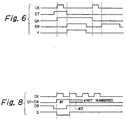
- the ultrasound probe 50 or 60 has provided in the input/output connector 53 (or 63) thereof, which places the probe in an electrically-connected state when selected, a switch 82 and a coil 83 of normally-off electromagnetic relays (stable relays), instead of the previously-described switch 53b (or 63b), and a circuit formed by a transistor 84, instead of the previously-mentioned switch controller 53a (or 63a), which excites the coil 83 of the electromagnetic relays, an AND circuit that turns on the transistor 84 and a shift register 86 that supplies a signal to the AND circuit 85.
- a data signal DT including a probe designation number and clock signal CK are supplied to the probe 50 or 60 from the relay controller 81 of the ultrasound imaging system 40.
- a high level signal is produced at the output terminal QA of the shift register 86 (provided in the corresponding probe), in accordance with the signals DT and CK both being high, and a high-level enable signal EN is supplied to the probe, both the high level signals QA and EN are ANDed by the AND circuit 85 to provide the result as a high level signal Y that will turn on the transistor 84 and excite the coil 83 of the electromagnetic relays so that the switch 82 is closed.
- the ultrasound transducers 55 (or 65) are thus energised to serve as electroacoustic transducers for the generation of an ultrasound.
- FIG. 7(a), 7(b) and 8 A variant of the probe information transmission system will be explained with reference to Figs. 7(a), 7(b) and 8.
- a combination of a three-state buffer and pin board is adopted.
- the ultrasound imaging system 40 has a probe information interface 46 connected to an 8-bit data line (for transmission of data signals D1 to D8), the individual lines of which are each grounded by means of a resistor 91, and the probe information interface 46 is also connected to a clock signal line CK and a control bit signal line D9.
- the probe 50 (or 60) is provided with a flip-flop 92, instead of the previously-mentioned input/output connector 53.
- the flip-flop 92 is supplied with the clock signal CK and control bit signal D9. These signals CK and D9 are so arranged that when an initial clock signal CK is supplied, the output signal Q of the flip-flop 92 takes a low level and when a second clock signal CK is supplied, the output signal takes a high level.
- a three-state buffer 93 is provided that is supplied at its two enable terminals EN with the output signal Q of the flip-flop 92 to input and output stored data.
- a pin board 94 instead of the previously-described probe coder 57 (or 67), to set probe information that is to be stored in the three-state buffer 94, and as many resistors 95 as there are pins, interposed between one end of the pin board 94 and the power source.
- the pin board 94 sets the necessary 8-bit information taking as "1" the position where a short-circuit bar 94a is inserted and as "0" the position where no such short-circuit bar is inserted.
- Such 8-bit information namely information relating to the ultrasound probe in question, is read out once to the buffer 93 and the result is transmitted to the ultrasound imaging system 40.
- the flip-flop 92 when the control bit signal D9 takes a low level while the clock signal CK takes a high level, the flip-flop 92 delivers an output signal Q at the same low level as the control signal D9 so that the three-state buffer 93 becomes active and stored probe information is supplied from the pin board 94 and delivered.
- the flip-flop 92 delivers an output signal Q at the same high level as the control bit signal D9 and the signal reflecting the stored probe information is no longer delivered from the three-state buffer 93 so that the low level will result from the grounding action of the resistors 91 of the ultrasound imaging system 40.
- the thermal monitoring system uses a thermistor that has a negative resistance-thermal characteristic.
- This thermal monitoring system has a thermal monitoring circuit that comprises a resistor and an operational amplifier in combination.
- a thermal protection circuit 100 provided instead of the previously-described thermal monitoring circuit 45 of the ultrasound imaging system 40, there is provided a resistor (R60) 101 between a wire connected to the thermistor 56 (66) of the probe 50 (60) and the power source Vcc, and a connection is made from the connection node between the thermistor 56 (66) and resistor 101 to the inversion input terminal (-) of an operational amplifier 102.
- Two resistors 103 and 104 having different resistances are connected in series between the power source Vcc and ground potential (0V) and a connection is made from the connection node between the resistor (R61) 103 and resistor (R62) 104 to the non-inversion input terminal (+) of the operational amplifier 102.
- the inversion input terminal (-) and output terminal of the operational amplifier 102 are wired to each other via a variable resistor (RV1) 105.
- the output terminal of the operational amplifier 102 is connected to the inversion input terminal (-) of a comparator 106.
- variable resistor (RV2) 107 There is connected between the power source Vcc and ground potential (0V), a variable resistor (RV2) 107 whose variable terminal is connected to the non-inversion input terminal (+) of an operational amplifier 108.
- the inversion input terminal (-) of the operational amplifier 108 is connected to the output terminal thereof.
- the output terminal of the operational amplifier 108 is connected to the non-inversion input terminal (+) of the comparator 106 by means of a resistor (R67) 109.
- the non-inversion input terminal (+) of the comparator 106 is connected to the output terminal thereof by means of a resistor (R68) 110.
- resistor (R69) 111 between the output terminal of the comparator 106 and power source Vcc.
- the thermistor 56 (or 66) incorporated in the probe 50 (60) has a reduced resistance. As shown in Fig. 10, the characteristic of output voltage (V2) vs. resistance of thermistor 56 (or 66) is negative.
- the output voltage (Vout) vs. temperature measured by the thermistor 56 (or 66) has a hysterisis characteristic. If the temperature rises above a predetermined value T2, the output voltage (Vout) goes to a low level. When the temperature falls below a predetermined value T1, the output voltage (Vout) goes up to a high level, whereby "chattering" phenomena of the temperature control are prevented.
- the thermal protection offered by this circuit is such that when the input signal V2 to the inversion input terminal (-) of the comparator 106 is larger than the input signal V1 to the non-inversion input terminal (+), the output signal from the output terminal is lowered so that the ultrasound transducers 55 (or 65) detect when the temperature has risen above the predetermined temperature and stops transmission of the electric signal that drives the probe. Thus, the probe is inhibited from generating more ultrasound.
- a measuring power source (-Vmm) is provided in the ultrasound imaging system 50, as shown in Fig. 12.
- an amplification circuit 112 using one of the transmission lines allocated to the number-of-probes system.
- an operational amplifier 114 whose non-inversion input terminal (+) is grounded and whose inversion input terminal (-) is connected to the output terminal thereof by means of a resistor (R2) 113.
- a negative power source (-Vmm) is connected to the other transmission line allocated to the number-of-probes detecting system, which line is connected to the plug connector 41.
- a resistor (R1) 115 (or 116) is connected between the two number-of-probes detecting system lines.
- the resistor 115 is an example of the probe check signal generator used in the number-of-probes detecting system of an ultrasound imaging system 40 embodying the present invention.
- resistors having the same resistance are provided in the respective ultrasound probes. More particularly, the resistor in each ultrasound probe causes a "unit" voltage drop when connected, so that by checking the overall voltage drop, it is possible to know how many probes are connected to the ultrasound imaging system 40, as shown in Fig. 13.
- the output voltage of the operational amplifier 114 is proportional to the number of probes connected to the ultrasound imaging system 40, the number of probes connected can be easily known by measuring the output voltage of the amplification circuit 112 in the number-of-probes detector 48. This is a very simple way to know the number of connected probes and can be done even with the cap 70 not attached.
- the reference numeral 121 indicates a switch for the latching relays, 122 a set coil of the latching relays, and 123 a reset coil of the latching relays.
- the set coil 122 and reset coil 123 of the latching relays are energised by transistors 124 and 125, respectively, which are turned on with output signals (transistor ON signals) from AND circuits 126 and 127, respectively.
- the AND circuit 126 delivers a high level signal (transistor ON signal)
- the AND circuit 127 delivers a high level signal (transistor ON signal).
- Other arrangements of the probe connecting system are similar to those in the first variant.
- the relay controller 81 delivers a clock signal CK and a data signal DT including a probe designation number
- the output signal delivered at the output terminal QA of the shift register 86 changes to a high level at the second rise of the clock signal CK.
- a control signal (enable signal) E1 is delivered from the relay controller 81
- the AND circuit 126 supplies a transistor on signal (Y1), the set coil 122 is excited and thus the switch 121 is closed.
- the ultrasound transducers 55 (or 65) produce an ultrasound.
- a high level signal is delivered at the output terminal QB of the shift register 86 synchronously with the rise of clock signal, and a control signal (enable signal) E2 is delivered from the relay controller 81.
- the AND circuit 127 generates a transistor ON signal (Y2), the reset coil 123 is excited and the switch 121 is opened.
- the ultrasound transducers 55 or 65 are stopped from generating ultrasound. Since it is necessary to supply a current only for operating the latching relays, the power consumption by the coil is very small.
- another embodiment of the probe information transmission system comprises a shift register 128 that can store each bit of an 8-bit data item and that shifts the stored data bits one by one toward the output terminal QH with one bit being delivered at the output terminal QH each time a clock signal CK is supplied, a pin board 129 so connected as to supply one bit into each storage area of the shift register 128, and a power source (5V) connected to each bit setting terminal of the pin board 129 by means of a resistor 130.
- the output terminal QH of the shift register 128 is connected to the transmission terminal for data signal DT of the socket connector 51 (or 61), the transmission terminal for data signal DT of the plug connector 52 (or 62) is connected to the first storage area (input terminals 1D and 3D) of the shift register 128, and the input terminals 1D and 3D are connected to ground by means of a resistor 131.
- the resistance of the resistor 131 is sufficiently high for transmission of a digital signal on the transmission line between the plug connector 52 (or 62) and shift register 128.
- insertion of at least one short-circuit bar 129a into the pin board 129 of the probe 50 (or 60) represents 8-bit data other than zero, and all 8 bits being zeros means that no probe is connected.
- the output from the shift register of the probe 60 is connected to the first storage area of the shift register 128 at the probe 50 by means of the plug connector 52.
- the probe information relating to the probe 50 is supplied to the probe information interface 46 and with the subsequent 8 clock signals CK, the probe information relating to the probe 60 is supplied to the probe information interface 46 through the shift register 128 at the probe 50.
- the thermal monitoring system uses a thermistor that has a negative resistance-thermal characteristic.
- This thermal monitoring system has a thermal monitoring circuit provided in the probe.
- the ultrasound imaging system 40 has a thermal data line (for transmission of thermal data TH) connected to ground by means of a resistor 132 and delivers a clock signal CK and a control bit signal DT from its probe information interface 46. Also it has a thermal monitoring receiver 133, instead of the previously-mentioned thermal monitor, which receives thermal data detected at the probe 50 (or 60).
- the probe 50 (or 60) comprises a flip-flop 92, instead of the previously-mentioned input/output connector 53 (or 63), which when supplied with the clock signal CK and the control bit signal DT, delivers a low level output signal Q at the first clock signal CK and a high level output signal Q at the second clock signal CK, a switch controller 134a that opens a switch 134b when the output signal Q from the flip-flop 92 has the high level, the switch 134b opening and closing under the control of the switch controller 134a, a thermistor 135, instead of the previously-described thermosensor 56 (or 66), which has a negative resistance-temperature characteristic, an amplifier 137, included in a thermal monitoring circuit 136, which amplifies the output signal from the thermistor 135, and a DC source 138 that supplies a current to the amplifier 137 and thermistor 135.
- the flip-flop 92 delivers an output signal Q at the same level as the control bit signal DT, the switch 134b is closed under control of the switch controller 134a to which the low level signal has been supplied, thereby transmitting to the thermal monitoring receiver 133 at the ultrasound imaging system 40 the thermal data TH measured by the thermistor 135 and amplified by the amplifier 137.
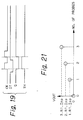
- a variant of the number-of-probes detecting system will be described that has a current source (Ipp) provided at the ultrasound imaging system 40 as shown in Fig. 20.
- the current source (Ipp) is connected to an end portion of one of a pair of transmission lines (signal lines) allocated to the number-of-probes detecting system, which end portion extends between the plug connector 41 of the ultrasound imaging system 40 and the number-of-probes detector 48, and the end portion of the other transmission line of the pair, which extends from the plug connector 41, is grounded.
- the probe 50 (or 60) there is provided between the socket connector 51 (or 61) and plug connector 52 (or 62) a resistor (R1) 141 (or 142) in series with one of the pair of signal lines (of the bus means) allocated to the number-of-probes detecting system.
- the resistors 141 and 142 are of the same resistance.
- the loopback circuit of this number-of-probes detecting system is completed when the socket connector 51 (or 61) of the probe 50 (or 60) is connected to the plug connector 41 of the ultrasound imaging system 40, and the socket connector 70a of the cap 70 is connected to the plug connector 52 (or 62) of the probe.
- the circuit is completed when the socket connector 61 of the second (outer) probe 60 is connected to the plug connector 52 (or 62) of the first probe (inner) 50 and the receptacle connector 70a of the cap 70 is connected to the plug connector 62 of the second probe 60 as shown in Fig. 20.
- the voltage rises in proportion to the constant current (Ipp) from the power source (Vpp) and is the product of the current (Ipp), the number of connected probes 50 (or 60) and the value (R1) of each resistor 141 and 142, which assures easy confirmation of the number of probes connected.
- Ipp constant current
- RV1 the value of each resistor 141 and 142
- one connecting device 13a (or 13b) of a first ultrasound probe 11a (or 11b) can be connected (fitted) to the single connecting device 10a of an ultrasound imaging system 10 and one connecting device 13b (or 13a) of a further ultrasound probe 11b (or 11a) is connected (fitted) to the other connecting device 14a (or 14b) of the first ultrasound probe 11a (or 11b).
- a plurality of ultrasound probes 11a and 11b can be connected to the single connecting device 10a of the ultrasound imaging system 10.
- a necessary number of ultrasound probes can be connected to the ultrasound imaging system 10 before starting an ultrasound study.
- the diagnosis can be done very easily and efficiently.
- FIG. 2 by opening and closing and input/output connector 21 provided at the ultrasound probe 11a (or 11b) the transducer 16a (or 16b) of an ultrasound probe 11a (or 11b) to be used is connected and disconnected respectively to the ultrasound imaging system 10. So one of the plurality of ultrasound probes 11a or 11b connected to the single connecting device 10a of the ultrasound imaging system 40 can be selected for use. No probe selecting device has to be provided at the ultrasound imaging system 10.
- the equipment construction can be considerably simplified, equipment operability during an ultrasound study can be greatly improved and the time for ultrasound diagnosis can be effectively shortened.
- probe information produced by the transducer 16a (16b) in an ultrasound probe 11a or 11b which is currently connected can only be used for correct electroacoustic transducing of diagnostic ultrasound when the probe temperature is within a predetermined range.
- probe information which measures the probe temperature of the operating probe, even when a plurality of ultrasound probes 11a and 11b are connected to the same connecting device 10a of the ultrasound imaging system 10, a desired probe cannot be mistaken for any other probe, thus ensuring a correct and rapid ultrasound diagnosis.
- each probe has a number-of-probes informing means 26 which cooperates with a number-of-probes detector 36 of the ultrasound imaging system 10 to confirm the number of ultrasound probes 11a or 11b connected to the same connecting device 10a of the ultrasound imaging system 10, thereby permitting the operator to easily know the number of connected probes even when a plurality of ultrasound probes are connected.
- a blind cap 12 can be attached to the connecting device 10a of the ultrasound imaging system 10 or the connecting device 14a or 14b of the ultrasound probe 11a or 11b.
Landscapes
- Physics & Mathematics (AREA)
- Engineering & Computer Science (AREA)
- Radar, Positioning & Navigation (AREA)
- Remote Sensing (AREA)
- Acoustics & Sound (AREA)
- Computer Networks & Wireless Communication (AREA)
- General Physics & Mathematics (AREA)
- Ultra Sonic Daignosis Equipment (AREA)
- Investigating Or Analyzing Materials By The Use Of Ultrasonic Waves (AREA)
Claims (20)
- Diagnostische Sonographievorrichtung mit:einer Ultraschallbildeinheit (10; 40); understen und zweiten Ultraschallsonden (11a, 11b; 50, 60), die jeweils ein Wandlermittel (16a, 16b; 55, 65) haben, das betriebsfähig ist, um Ultraschallsignale in einen zu untersuchenden Körper zu emittieren und um Ultraschalldaten zu erzeugen, die Reflexionen von solchen Signalen in dem Körper darstellen, welche Sonden beide mit der Ultraschallbildeinheit verbunden sind, wenn die Vorrichtung in Gebrauch ist, so daß eine ausgewählte der Sonden ihre Ultraschalldaten der Bildeinheit zur Analyse und Anzeige durch ein Monitormittel (10b; 42) der Ultraschallbildeinheit zuführen kann;dadurch gekennzeichnet, daß:jede Sonde jeweilige erste und zweite Verbindungsvorrichtungen (13a, 14a, 13b, 14b; 51, 52, 61, 62) hat, so daß die ersten und zweiten Sonden (11a, 11b; 50, 60) in einer gestapelten Konfiguration zusammen verbunden sein können, bei der die erste Verbindungsvorrichtung (13b; 61) der zweiten Sonde (11b; 60) mit der zweiten Verbindungsvorrichtung (14a; 52) der ersten Sonde (11a; 50) verbunden ist, wobei jede Sonde auch ein Busmittel (15a, 15b) hat, welches ihre ersten und zweiten Verbindungsvorrichtungen (13a, 14a, 13b, 14b; 51, 52, 61, 62) miteinander verbindet, welches Busmittel auch mit dem Wandlermittel der Sonde verbunden ist, wenn die betreffende Sonde zur Verwendung ausgewählt ist, so daß die Ultraschalldaten, die durch das Wandlermittel erzeugt werden, dem Busmittel zugeführt werden; unddie Ultraschallbildeinheit (10; 40) ein Sondenselektionsmittel (38; 42a; 81) enthält, das betriebsfähig ist, um Sondenselektionssignale zur Verwendung durch die Sonden zu erzeugen, um zu bestimmen, welche von ihnen für den Gebrauch selektiert ist, und auch eine Verbindungsvorrichtung (10a; 41) in der Form eines Steckverbinders des Stecker- oder Buchsentyps hat, an der sie die Sondenselektionssignale bereitstellt und solche Ultraschalldaten empfängt, mit welcher Verbindungsvorrichtung (10a; 41) die erste Verbindungsvorrichtung (13a; 51) der ersten Sonde (11a; 50) verbunden sein kann, wenn die Sonden in der gestapelten Konfiguration zusammen verbunden sind, so daß die jeweiligen Busmittel (15a, 15b) der ersten und zweiten Sonden mit der Verbindungsvorrichtung (10a; 41) der Bildeinheit (10; 40) seriell verbunden sind und dazu dienen können, die Sondenselektionssignale von der Bildeinheit zu beiden Sonden zu übertragen und von der selektierten Sonde die Ultraschalldaten, die durch jene Sonde erzeugt werden, zurück zu der Bildeinheit zu übertragen.
- Vorrichtung nach Anspruch 1, bei der eine (14a, 14b; 52, 62) der ersten und zweiten Verbindungsvorrichtungen von jeder Sonde ein Steckverbinder des Steckertyps ist und die andere (13a, 13b; 51, 61) von jenen zwei Verbindungsvorrichtungen ein Steckverbinder des Buchsentyps ist.
- Vorrichtung nach Anspruch 1 oder 2, bei der jede Sonde ferner ein Eingangs-/Ausgangsverbindungsmittel (21; 53, 63; 82-86; 86, 121-127) enthält, das betriebsfähig ist, um eine Verbindung zwischen dem Busmittel (15a, 15b) und dem Wandlermittel (16a, 16b; 55, 65) der betreffenden Sonde gemäß den Sondenselektionssignalen, die von dem Sondenselektionsmittel (38; 42a; 81) empfangen werden, herzustellen oder zu unterbrechen.
- Vorrichtung nach irgendeinem vorhergehenden Anspruch, bei der jede Sonde ferner ein Sondeninformationseinstellmittel (24; 57, 67; 92-95; 128-131) enthält, das vorbestimmte Sondeninformationen bezüglich der Sonde hat, und das Monitormittel (10b; 42) der Bildeinheit eine Sondeninformationsschnittstelle (33; 46) hat, die betriebsfähig ist, um die Sondeninformationen der verbundenen Sonden zu lesen.
- Vorrichtung nach Anspruch 4, bei der das Sondeninformationseinstellmittel (24; 57, 67; 92-95; 128-131) die Sondeninformationen für die Bildeinheit als Reaktion auf ein vorbestimmtes Steuersignal, das durch die Sondeninformationsschnittstelle (33; 46) zugeführt wird, in codierter Form bereitstellt.
- Vorrichtung nach Anspruch 5 in Verbindung mit Anspruch 3, bei der die Sondeninformationen Daten bezüglich des Wandlermittels der Sonde enthalten und der Bildeinheit über das Eingangs-/Ausgangsverbindungsmittel (21; 53, 63) zugeführt werden.
- Vorrichtung nach irgendeinem vorhergehenden Anspruch, bei der jede Sonde ferner ein Thermosensormittel (23; 56, 66; 134-138) enthält, das betriebsfähig ist, um die Temperatur der Sonde zu detektieren und um ein Thermosensorsignal zu der Bildeinheit zu senden, das die detektierte Temperatur verkörpert, und das Monitormittel (10b; 42) ferner ein Temperaturüberwachungsmittel (34; 45; 100; 133) enthält, das bei Empfang solch eines Thermosensorsignals von einer der Sonden betriebsfähig ist, um aus ihm eine Messung der Temperatur der betreffenden Sonde abzuleiten.
- Vorrichtung nach irgendeinem vorhergehenden Anspruch, bei der jede Sonde ein Verbindungsstatusanzeigemittel (25; 58, 68) enthält, zum Vorsehen einer vorbestimmten visuellen, auralen oder taktilen Meldung, wenn das Wandlermittel der Sonde mit ihrem Busmittel verbunden ist.
- Vorrichtung nach Anspruch 8, bei der das Verbindungsstatusanzeigemittel (25; 58, 68) durch ein Anzeigetreibersignal, das durch das Anzeigetreibermittel (35; 47) des Monitormittels (10b; 42) erzeugt wird, aktiviert wird, um seine Meldung zu erzeugen.
- Vorrichtung nach irgendeinem vorhergehenden Anspruch, bei der die Bildeinheit ein Anzeigemittel (201) zum Anzeigen von Informationen bezüglich aller Sonden hat, die mit der Einheit verbunden sind.
- Vorrichtung nach Anspruch 10, bei der die angezeigten Informationen wenigstens einen der folgenden Typen von Informationen enthalten:den Sondentyp; die Sondenanwendung; und die Sondenanzahl.
- Vorrichtung nach Anspruch 10 oder 11, bei der die Bildeinheit ein Selektionssteuermittel hat, das selektiv steuerbar ist, wenn das Anzeigemittel (201) solche Informationen bezüglich der Sonden anzeigt, um die Auswahl der Sonde vorzunehmen, die von den Sonden zu verwenden ist, über die Informationen angezeigt werden.
- Vorrichtung nach irgendeinem vorhergehenden Anspruch, die wenigstens drei solche Ultraschallsonden (11a, 11b, 11c ..., 11n) hat, die alle in solch einer gestapelten Konfiguration zusammen verbunden sein können, wobei die erste Verbindungsvorrichtung der dritten Sonde (11c) mit der zweiten Verbindungsvorrichtung (14b; 62) der zweiten Sonde (11b; 60) verbunden ist, und so weiter mit jeder weiteren Sonde der Vorrichtung.
- Vorrichtung nach irgendeinem vorhergehenden Anspruch, die ferner eine Blindkappe (12; 70) zur Verbindung mit der zweiten Verbindungsvorrichtung der letzten Sonde in der gestapelten Konfiguration enthält, um Anschlüsse von jener zweiten Verbindungsvorrichtung vor äußeren Signalen abzuschirmen.
- Vorrichtung nach irgendeinem vorhergehenden Anspruch, bei der das Monitormittel (10b; 42) der Bildeinheit ein Sondenanzahldetektionsmittel (36; 48, 112) enthält, und jede Sonde ein Sondenprüfsignalerzeugungsmittel (26; 54, 64; 115, 116; 141, 142) enthält, welches Sondenanzahldetektionsmittel (36) mit dem jeweiligen Sondenprüfsignalerzeugungsmittel (26) der Sonden kooperiert, wenn die Sonden in der gestapelten Konfiguration mit der Bildeinheit verbunden sind, um die Anzahl von Sonden zu detektieren, die in jener gestapelten Konfiguration mit der Bildeinheit verbunden sind, oder um eine Veränderung jener Anzahl zu detektieren.
- Vorrichtung nach Anspruch 15, bei der:
das Sondenprüfsignalerzeugungsmittel (115, 116) von jeder Sonde (50, 60) einen Widerstand (115, 116) umfaßt, der zwischen jeweiligen ersten und zweiten Signalleitungen des Busmittels so verbunden ist, daß dann, wenn die Sonden in der gestapelten Konfiguration mit der Bildeinheit verbunden sind, die jeweiligen Widerstände der Sonden zwischen den ersten und zweiten Signalleitungen parallel miteinander verbunden sind; und
das Sondenanzahldetektionsmittel (48; 112) eine Spannungsquelle umfaßt, die mit der Verbindungsvorrichtung (41) der Bildeinheit (40) verbunden ist, zum Anwenden eines vorbestimmten konstanten Potentials (-Vmm) auf die erste Signalleitung, und ein Verstärkermittel (112), das auch mit der Verbindungsvorrichtung (41) der Bildeinheit verbunden ist, zum Vorsehen eines Signals, das von dem Potential der zweiten Signalleitung abhängt. - Vorrichtung nach Anspruch 15 in Verbindung mit Anspruch 14, bei der:
in jeder Sonde (50, 60) das Sondenprüfsignalerzeugungsmittel (141, 142) einen Widerstand (141, 142) umfaßt, der mit einer von einem Paar von Signalleitungen des Busmittels, das sich zwischen den ersten und zweiten Verbindungsvorrichtungen (51, 52, 61, 62) erstreckt, seriell verbunden ist;
die Blindkappe (70) ein Mittel enthält zum Miteinanderverbinden der zwei Signalleitungen des Paares in der letzten Sonde der gestapelten Konfiguration, um eine Rückschleifenverbindung zu bilden, die alle Sonden durchläuft; und
das Sondenanzahldetektionsmittel (48) eine Stromquelle umfaßt, die mit der Verbindungsvorrichtung (41) der Bildeinheit (40) verbunden ist, zum Verursachen, daß ein vorbestimmter konstanter Strom (Ipp) durch die Rückschleifenverbindung fließt, so daß auf der Basis der Potentialdifferenz zwischen den zwei Enden jener Rückschleifenverbindung die Anzahl von Sonden, die in der gestapelten Konfiguration verbunden sind, bestimmt werden kann. - Vorrichtung nach irgendeinem vorhergehenden Anspruch, bei der:
das Wandlermittel (16a, 16b; 55, 65) von jeder Sonde ein elektroakustisches Wandlermittel ist, das elektrische Treibersignale in die Ultraschallsignale konvertiert, die in den Körper zu emittieren sind, und das die Ultraschallreflexionen in elektrische Signale konvertiert, die die Ultraschalldaten darstellen; und
das Monitormittel (10b) ein Sendermittel (31; 43) enthält, zum Senden der elektrischen Treibersignale für das Wandlermittel der Sonde zu der ausgewählten Sonde, und ein Empfängermittel (32; 44) zum Empfangen und Verstärken der elektrischen Signale, die durch das Wandlermittel der ausgewählten Sonde erzeugt werden. - Ultraschallsonde, die eine der Ultraschallsonden (11a, 11b; 50, 60) der diagnostischen Sonographievorrichtung nach irgendeinem vorhergehenden Anspruch ist.
- Ultraschallbildeinheit der diagnostischen Sonographievorrichtung nach irgendeinem der Ansprüche 1 bis 18.
Applications Claiming Priority (2)
| Application Number | Priority Date | Filing Date | Title |
|---|---|---|---|
| JP3207891A JP2683966B2 (ja) | 1991-08-20 | 1991-08-20 | スタック接続方式の超音波プローブおよび超音波診断装置ならびに超音波診断システム |
| JP207891/91 | 1991-08-20 |
Publications (2)
| Publication Number | Publication Date |
|---|---|
| EP0528693A1 EP0528693A1 (de) | 1993-02-24 |
| EP0528693B1 true EP0528693B1 (de) | 1997-07-30 |
Family
ID=16547283
Family Applications (1)
| Application Number | Title | Priority Date | Filing Date |
|---|---|---|---|
| EP92307611A Expired - Lifetime EP0528693B1 (de) | 1991-08-20 | 1992-08-20 | Schallabbildung-Diagnoseneinrichtung mit mehreren Ultraschallproben |
Country Status (4)
| Country | Link |
|---|---|
| US (1) | US5318027A (de) |
| EP (1) | EP0528693B1 (de) |
| JP (1) | JP2683966B2 (de) |
| DE (1) | DE69221227T2 (de) |
Cited By (1)
| Publication number | Priority date | Publication date | Assignee | Title |
|---|---|---|---|---|
| DE102012111427A1 (de) * | 2012-11-26 | 2014-05-28 | Endress + Hauser Flowtec Ag | Feldgerät, insbesondere Ultraschall-Durchflussmessgerät |
Families Citing this family (34)
| Publication number | Priority date | Publication date | Assignee | Title |
|---|---|---|---|---|
| US5673698A (en) * | 1994-04-21 | 1997-10-07 | Hitachi Medical Corporation | Multichannel ultrasonic diagnosis apparatus |
| JPH07289553A (ja) * | 1994-04-22 | 1995-11-07 | Hitachi Medical Corp | 超音波断層装置 |
| US5505203A (en) * | 1994-11-23 | 1996-04-09 | General Electric Company | Method and apparatus for automatic transducer selection in ultrasound imaging system |
| US5744555A (en) * | 1994-11-25 | 1998-04-28 | Eastman Chemical Company | Process for the synthesis of elastomeric polypropylene |
| US5615678A (en) * | 1994-11-25 | 1997-04-01 | General Electric Company | Integral auto-selecting yoke/transducer connector for ultrasound transducer probe |
| US5544660A (en) * | 1995-03-30 | 1996-08-13 | Boston Scientific Corp. | Acoustic imaging catheter and method of operation |
| US5611343A (en) * | 1995-04-05 | 1997-03-18 | Loral Aerospace Corp. | High resolution three-dimensional ultrasound imaging |
| US5776065A (en) * | 1996-09-18 | 1998-07-07 | Acuson Corporation | Apparatus and method for controlling an ultrasound transducer array |
| US5882310A (en) * | 1997-12-01 | 1999-03-16 | Acuson Corporation | Ultrasound transducer connector and multiport imaging system receptacle arrangement |
| US6811902B2 (en) * | 2001-07-31 | 2004-11-02 | Delphi Technologies, Inc. | Battery pack having improved battery cell terminal configuration |
| US6500126B1 (en) * | 2001-12-20 | 2002-12-31 | Koninklijke Philips Electronics N.V. | Ultrasound system transducer adapter |
| US7534211B2 (en) * | 2002-03-29 | 2009-05-19 | Sonosite, Inc. | Modular apparatus for diagnostic ultrasound |
| US6629928B1 (en) * | 2002-11-08 | 2003-10-07 | Koninklijke Philips Electronics N.V. | Modular transducer connection system |
| US7591786B2 (en) * | 2003-01-31 | 2009-09-22 | Sonosite, Inc. | Dock for connecting peripheral devices to a modular diagnostic ultrasound apparatus |
| JP3669990B2 (ja) * | 2003-02-12 | 2005-07-13 | ファナック株式会社 | インバータ装置の接地方法及びインバータ装置 |
| US20050113690A1 (en) * | 2003-11-25 | 2005-05-26 | Nahi Halmann | Methods and systems for providing portable device extended resources |
| WO2005053664A2 (en) | 2003-11-26 | 2005-06-16 | Teratech Corporation | Modular portable ultrasound systems |
| EP1787586B1 (de) * | 2004-08-31 | 2008-06-25 | Kabushiki Kaisha Toshiba | Untersuchungsapparat mit Ultraschallsonde, Ultraschalluntersuchungsgerät und Untersuchungsmethode mit einer Ultraschallsonde |
| US20070232907A1 (en) * | 2006-04-03 | 2007-10-04 | Laurent Pelissier | Methods and systems for configuring ultrasound systems for ultrasound examinations |
| US7505363B2 (en) | 2006-04-10 | 2009-03-17 | Airmar Technology Corporation | Automatic switch for marine sounders |
| JP2008061938A (ja) * | 2006-09-11 | 2008-03-21 | Toshiba Corp | 超音波プローブ、超音波診断装置及び超音波プローブ監視システム |
| US8600299B2 (en) * | 2006-11-10 | 2013-12-03 | Siemens Medical Solutions Usa, Inc. | Transducer array imaging system |
| US9295444B2 (en) | 2006-11-10 | 2016-03-29 | Siemens Medical Solutions Usa, Inc. | Transducer array imaging system |
| US7984651B2 (en) * | 2006-11-10 | 2011-07-26 | Penrith Corporation | Transducer array imaging system |
| US8143898B1 (en) | 2007-04-06 | 2012-03-27 | Unisyn Medical Technologies, Inc. | Systems and methods for reconfiguring an ultrasound device |
| US8033174B2 (en) * | 2007-09-07 | 2011-10-11 | Medison Co. Ltd. | Ultrasound diagnostic system |
| JP2009219794A (ja) * | 2008-03-18 | 2009-10-01 | Olympus Medical Systems Corp | 超音波診断装置 |
| JP5501585B2 (ja) * | 2008-08-19 | 2014-05-21 | ジーイー・メディカル・システムズ・グローバル・テクノロジー・カンパニー・エルエルシー | 超音波診断装置及びアダプタ |
| KR101263831B1 (ko) * | 2011-09-19 | 2013-05-13 | 삼성메디슨 주식회사 | 진단영상 생성장치, 프로브, 프로브를 제어하는 방법 및 진단영상을 생성하는 방법 |
| JP6024120B2 (ja) * | 2012-02-24 | 2016-11-09 | セイコーエプソン株式会社 | 超音波プローブ、プローブヘッド、電子機器及び診断装置 |
| DE102013101158A1 (de) * | 2013-02-06 | 2014-08-07 | Karl Storz Gmbh & Co. Kg | Medizinische Vorrichtung und Verfahren zum Konfigurieren eines medizinischen Systems |
| CN104107067A (zh) * | 2013-04-16 | 2014-10-22 | 深圳迈瑞生物医疗电子股份有限公司 | 一种支持多探头同步扫描的超声诊断设备及方法 |
| US10816638B2 (en) * | 2014-09-16 | 2020-10-27 | Symbol Technologies, Llc | Ultrasonic locationing interleaved with alternate audio functions |
| KR102390059B1 (ko) * | 2015-02-13 | 2022-04-25 | 삼성메디슨 주식회사 | 초음파 영상 장치 및 초음파 영상 장치의 제어 방법 |
Citations (1)
| Publication number | Priority date | Publication date | Assignee | Title |
|---|---|---|---|---|
| EP0451463A2 (de) * | 1990-02-27 | 1991-10-16 | Acoustic Imaging Technologies Corporation | Auswahltastatur für mehrere Wandler |
Family Cites Families (12)
| Publication number | Priority date | Publication date | Assignee | Title |
|---|---|---|---|---|
| JPS5615734A (en) * | 1979-07-20 | 1981-02-16 | Tokyo Shibaura Electric Co | Ultrasonic diagnosing device |
| JPS6116658U (ja) * | 1984-07-03 | 1986-01-30 | 三菱電機株式会社 | 優先順位移行装置 |
| JPH0636795B2 (ja) * | 1985-07-23 | 1994-05-18 | 株式会社東芝 | 超音波診断装置 |
| JPH0734797B2 (ja) * | 1986-12-18 | 1995-04-19 | 株式会社日立メデイコ | 超音波診断装置 |
| JPS63242246A (ja) * | 1987-03-31 | 1988-10-07 | 株式会社 日立メデイコ | 体腔内用超音波探触子 |
| JPH01254150A (ja) * | 1988-04-04 | 1989-10-11 | Fujitsu Ltd | 超音波診断装置 |
| JPH0215459A (ja) * | 1988-07-04 | 1990-01-19 | Toshiba Corp | ディスク再生機の接続装置 |
| JPH066805Y2 (ja) * | 1988-08-26 | 1994-02-23 | 横河メディカルシステム株式会社 | 超音波診断装置 |
| JPH02201679A (ja) * | 1989-01-31 | 1990-08-09 | Toshiba Corp | システム構成認識方式 |
| JPH02116345U (de) * | 1989-03-01 | 1990-09-18 | ||
| JPH0382454A (ja) * | 1989-08-28 | 1991-04-08 | Fujitsu Ltd | 超音波診断装置 |
| JPH03182236A (ja) * | 1989-12-11 | 1991-08-08 | Aloka Co Ltd | 超音波診断装置 |
-
1991
- 1991-08-20 JP JP3207891A patent/JP2683966B2/ja not_active Expired - Fee Related
-
1992
- 1992-08-20 US US07/932,965 patent/US5318027A/en not_active Expired - Lifetime
- 1992-08-20 EP EP92307611A patent/EP0528693B1/de not_active Expired - Lifetime
- 1992-08-20 DE DE69221227T patent/DE69221227T2/de not_active Expired - Fee Related
Patent Citations (1)
| Publication number | Priority date | Publication date | Assignee | Title |
|---|---|---|---|---|
| EP0451463A2 (de) * | 1990-02-27 | 1991-10-16 | Acoustic Imaging Technologies Corporation | Auswahltastatur für mehrere Wandler |
Cited By (2)
| Publication number | Priority date | Publication date | Assignee | Title |
|---|---|---|---|---|
| DE102012111427A1 (de) * | 2012-11-26 | 2014-05-28 | Endress + Hauser Flowtec Ag | Feldgerät, insbesondere Ultraschall-Durchflussmessgerät |
| US10145714B2 (en) | 2012-11-26 | 2018-12-04 | Endress + Hauser Flowtec Ag | Ultrasonic flow measuring device having a downstream resistance network for improved zero point stability |
Also Published As
| Publication number | Publication date |
|---|---|
| DE69221227T2 (de) | 1997-11-27 |
| US5318027A (en) | 1994-06-07 |
| EP0528693A1 (de) | 1993-02-24 |
| JPH0542143A (ja) | 1993-02-23 |
| JP2683966B2 (ja) | 1997-12-03 |
| DE69221227D1 (de) | 1997-09-04 |
Similar Documents
| Publication | Publication Date | Title |
|---|---|---|
| EP0528693B1 (de) | Schallabbildung-Diagnoseneinrichtung mit mehreren Ultraschallproben | |
| US6270463B1 (en) | System and method for measuring temperature in a strong electromagnetic field | |
| EP0558051B1 (de) | Kabelendstück-Zustandsdetektion | |
| US5509422A (en) | Clinical thermometer with pulsimeter | |
| EP2631642B1 (de) | Ultraschallvorrichtung | |
| US20060101896A1 (en) | Apparatus and methods for testing acoustic probes and systems | |
| US8033174B2 (en) | Ultrasound diagnostic system | |
| US5255682A (en) | Ultrasonic diagnostic imaging systems with scanhead indicators | |
| US7278289B2 (en) | Apparatus and methods for testing acoustic systems | |
| US7007539B2 (en) | Apparatus and methods for interfacing acoustic testing apparatus with acoustic probes and systems | |
| JP3967429B2 (ja) | 超音波診断装置 | |
| JPS6222638A (ja) | 超音波探触子接続用アダプタ | |
| KR101510679B1 (ko) | 초음파 프로브 | |
| JPH10127632A (ja) | 超音波診断装置 | |
| US20190343483A1 (en) | Systems, methods, and apparatuses for fluid ingress detection for ultrasound transducers | |
| JP2006345964A (ja) | 超音波装置 | |
| JP4632527B2 (ja) | 超音波プローブおよび超音波診断装置 | |
| JP4421351B2 (ja) | 超音波診断装置 | |
| JPS5814219B2 (ja) | 体腔插入プロ−ブを用いた超音波診断装置のプロ−ブ位置検出器 | |
| US20210295978A1 (en) | System and Method for Controlling Operability of Multiple Medical Devices | |
| SU1412455A1 (ru) | Устройство дл проверки многожильного кабел | |
| JPH0984785A (ja) | 超音波診断装置 | |
| CA1288818C (en) | Test meters | |
| JPH0696005B2 (ja) | 超音波診断装置 | |
| JPH08128996A (ja) | 超音波画像化装置 |
Legal Events
| Date | Code | Title | Description |
|---|---|---|---|
| PUAI | Public reference made under article 153(3) epc to a published international application that has entered the european phase |
Free format text: ORIGINAL CODE: 0009012 |
|
| AK | Designated contracting states |
Kind code of ref document: A1 Designated state(s): DE FR |
|
| 17P | Request for examination filed |
Effective date: 19930430 |
|
| 17Q | First examination report despatched |
Effective date: 19950627 |
|
| GRAG | Despatch of communication of intention to grant |
Free format text: ORIGINAL CODE: EPIDOS AGRA |
|
| GRAH | Despatch of communication of intention to grant a patent |
Free format text: ORIGINAL CODE: EPIDOS IGRA |
|
| GRAH | Despatch of communication of intention to grant a patent |
Free format text: ORIGINAL CODE: EPIDOS IGRA |
|
| GRAA | (expected) grant |
Free format text: ORIGINAL CODE: 0009210 |
|
| AK | Designated contracting states |
Kind code of ref document: B1 Designated state(s): DE FR |
|
| REF | Corresponds to: |
Ref document number: 69221227 Country of ref document: DE Date of ref document: 19970904 |
|
| ET | Fr: translation filed | ||
| PLBE | No opposition filed within time limit |
Free format text: ORIGINAL CODE: 0009261 |
|
| STAA | Information on the status of an ep patent application or granted ep patent |
Free format text: STATUS: NO OPPOSITION FILED WITHIN TIME LIMIT |
|
| 26N | No opposition filed | ||
| REG | Reference to a national code |
Ref country code: FR Ref legal event code: TP |
|
| PGFP | Annual fee paid to national office [announced via postgrant information from national office to epo] |
Ref country code: FR Payment date: 20050809 Year of fee payment: 14 |
|
| PGFP | Annual fee paid to national office [announced via postgrant information from national office to epo] |
Ref country code: DE Payment date: 20050818 Year of fee payment: 14 |
|
| PG25 | Lapsed in a contracting state [announced via postgrant information from national office to epo] |
Ref country code: DE Free format text: LAPSE BECAUSE OF NON-PAYMENT OF DUE FEES Effective date: 20070301 |
|
| REG | Reference to a national code |
Ref country code: FR Ref legal event code: ST Effective date: 20070430 |
|
| PG25 | Lapsed in a contracting state [announced via postgrant information from national office to epo] |
Ref country code: FR Free format text: LAPSE BECAUSE OF NON-PAYMENT OF DUE FEES Effective date: 20060831 |