EP0528693A1 - Stapel-Verbinder-Ultraschallprobe, Einrichtung für Ultraschall-Bildaufnahme und Ultraschall-Diagnoseeinrichtung - Google Patents
Stapel-Verbinder-Ultraschallprobe, Einrichtung für Ultraschall-Bildaufnahme und Ultraschall-Diagnoseeinrichtung Download PDFInfo
- Publication number
- EP0528693A1 EP0528693A1 EP92307611A EP92307611A EP0528693A1 EP 0528693 A1 EP0528693 A1 EP 0528693A1 EP 92307611 A EP92307611 A EP 92307611A EP 92307611 A EP92307611 A EP 92307611A EP 0528693 A1 EP0528693 A1 EP 0528693A1
- Authority
- EP
- European Patent Office
- Prior art keywords
- ultrasound
- probe
- imaging system
- probes
- ultrasound imaging
- Prior art date
- Legal status (The legal status is an assumption and is not a legal conclusion. Google has not performed a legal analysis and makes no representation as to the accuracy of the status listed.)
- Granted
Links
Images


Classifications
-
- G—PHYSICS
- G01—MEASURING; TESTING
- G01S—RADIO DIRECTION-FINDING; RADIO NAVIGATION; DETERMINING DISTANCE OR VELOCITY BY USE OF RADIO WAVES; LOCATING OR PRESENCE-DETECTING BY USE OF THE REFLECTION OR RERADIATION OF RADIO WAVES; ANALOGOUS ARRANGEMENTS USING OTHER WAVES
- G01S15/00—Systems using the reflection or reradiation of acoustic waves, e.g. sonar systems
- G01S15/88—Sonar systems specially adapted for specific applications
- G01S15/89—Sonar systems specially adapted for specific applications for mapping or imaging
- G01S15/8906—Short-range imaging systems; Acoustic microscope systems using pulse-echo techniques
- G01S15/899—Combination of imaging systems with ancillary equipment
-
- G—PHYSICS
- G01—MEASURING; TESTING
- G01S—RADIO DIRECTION-FINDING; RADIO NAVIGATION; DETERMINING DISTANCE OR VELOCITY BY USE OF RADIO WAVES; LOCATING OR PRESENCE-DETECTING BY USE OF THE REFLECTION OR RERADIATION OF RADIO WAVES; ANALOGOUS ARRANGEMENTS USING OTHER WAVES
- G01S15/00—Systems using the reflection or reradiation of acoustic waves, e.g. sonar systems
- G01S15/88—Sonar systems specially adapted for specific applications
- G01S15/89—Sonar systems specially adapted for specific applications for mapping or imaging
- G01S15/8906—Short-range imaging systems; Acoustic microscope systems using pulse-echo techniques
Definitions
- the present invention relates to a connectable-as -stacked (will be referred to as "stack-connectable” hereafter) ultrasound probe, a plurality of which can be connected to at least a probe connector of an ultrasound imaging system, an ultrasound imaging system and a diagnostic sonography system.
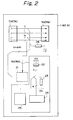
- Fig. 22 shows the construction of a conventional ultrasound imaging system indicated generally with a reference numeral 1.
- the reference numerals 1a and 1b indicate connectors, respectively, to which the connectors of ultrasound probes are to be connected.
- the numerals 2a and 2b indicate select switches, respectively, either of which is used to select the connector 1a or 1b to which an ultrasound probe 7 the operator is going to use is connected.
- the reference numeral 3 indicates a transmission circuit that generates and supplies an electric signal that will drive an electroacoustic or ultrasound transducer provided in the ultrasound probe. An ultrasound is transmitted from the probe 7 and directed into the body of an examinee. The ultrasound is reflected there and returned to the probe 7.
- the numeral 4 indicates a reception circuit that amplifies a received electric signal derived from the conversion by the electroacoustic transducer of the reflected ultrasound or echo from inside the examinee's body.
- the reference numeral 5 indicates a probe information interface that reads the information indicative of the type of ultrasound probe 7 connected to the ultrasound imaging system 1.
- the numeral 6 indicates a thermal monitoring circuit having a thermistor that detects the temperature inside the ultrasound probe 7.
- the thermal monitoring circuit 6 comprises thermosensors 6a and 6b and thermosensor select switches 6c and 6d, for each of the ultrasound probes 7.
- the ultrasound probe 7 comprises a connector that is to be connected to the connector 1a or 1b of the ultrasound imaging system 1, a group of electroacoustic transducers 7b that generate ultrasound, a thermistor 7c that detects the temperature of the ultrasound probe 7, and a probe information coder 7d that encodes and holds the information indicative of the type of the ultrasound probe 7.
- the ultrasound imaging system 1 is provided with a plurality of connecting devices (connectors 1a, 1b) to each of which one ultrasound probe 7 is connectable.
- a desired ultrasound probes is selected for use in a clinical study by operating one of the corresponding select switches 2a and 2b provided on the ultrasound imaging system 1.
- the number of connecting devices that can be provided on one ultrasound imaging system 1 is the upper limit of the number of ultrasound probes 7 simultaneously connectable to one ultrasound imaging system 1.
- the present invention has an object to overcome the above-mentioned drawbacks of the prior art by providing a stack-connectable ultrasound probe and an ultrasound imaging system simultaneously connectable to the connecting device thereof and a plurality of ultrasound probes among which a desire prove one can be used as freely selected.
- an ultrasound probe intended for use in a diagnostic sonography system comprising an ultrasound imaging system having a connecting device for the connection of ultrasound probes and that takes the form of either a plug or receptacle connector and a monitor supplied with ultrasound data from one of the probes through the connecting device and analyses and displays the ultrasound data, and a plurality of the probes can be connected to the ultrasound imaging system, each of the ultrasound probes comprising a first connecting device connectable to either the connecting device of the ultrasound imaging system or the connecting device of another ultrasound probe; a second connecting device connectable to the connecting device to the first connecting device by means of an interconnecting wire and to the connecting device of one of the other ultrasound probes, and a transducer branched from the interconnecting wire between the first and second connecting devices.
- an ultrasound imaging system intended for use in a diagnostic sonography system
- an ultrasound imaging system having a connecting device for the connection of ultrasound probes and that takes the form of either a plug or receptacle connector and a monitor supplied with ultrasound data from one of the probes through the connecting device and analyses and displays the ultrasound data, and a plurality of the probes can be connected to the ultrasound imaging system
- the diagnostic sonography system further having: a means for transmitting to the monitor an electric signal that will generate an ultrasound signal; and a means for receiving and amplifying an electric signal derived from conversion by an electroacoustic transducer of the ultrasound probe of the ultrasound reflected from inside the examinee
- the ultrasound imaging system further comprising at least one of the following as selected: a probe information interface for reading the information on the ultrasound probe connected; and a display driving means for generating a signal that will drive a connected-status displaying means provided in the ultrasound probe.
- a diagnostic sonography system comprising an ultrasound imaging system having a connecting device for the connection of ultrasound probes and that forms either a plug or receptacle connector and a monitor supplied with ultrasound data from one of the probes through the connecting device and analyses and displays the ultrasound data, and a plurality of the probes can be connected to the ultrasound imaging system, wherein a plurality of the ultrasound probes are connected as stacked to at least one connecting device of the ultrasound imaging system and at least one of the ultrasound probes connected as stacked to each other can be selected for scanning in response to a switch controller provided in the ultrasound imaging system.
- a diagnostic sonography system 200 comprising ultrasound probes 11 and an ultrasound imaging system 10, to which the ultrasound probes 11 are connected, will be briefly discussed below.
- Fig. 1 shows the construction of the diagnostic sonography system 200 in which a plurality of ultrasound probes 11 are connected to a single connecting device 10a of the ultrasound imaging system 10.
- the ultrasound scanner 10 comprises the probe connecting device 10a taking the form of a plug or receptacle and a monitor 10b that receives and analyses the data from the probe through the connecting device 10b and displays necessary data.
- the reference numerals 11a and 11b indicate ultrasound probes, respectively, comprising connecting devices 13a and 13b adapted for connection to the connecting device 10a of the ultrasound imaging system 10, other connecting devices 14a and 14b connected and appropriately wired to the connecting devices 13 and 13b, respectively, interconnecting wires 15a and 15b laid between the connecting devices 13a and 14a and between 13b and 14b, respectively, and transducers 16a and 16b connected in parallel to the connecting devices 14a and 14b, respectively, by branching the interconnecting wires 15a and 15b.
- the reference numeral 12 indicates a blind cap that comprises a connecting device 15 to be connected to the opened connecting device 10a of the ultrasound imaging system 10 or the opened connecting device 14a or 14b of the ultrasound probe 11a or 11b.
- the connecting terminal of the connecting device 15 is short-circuited opposite the connected side.
- the ultrasound probe 11a (or 11b) has an input/output connector 21 for setting the connection between the transducer 16a (or 16b) and ultrasound imaging system 10.
- the transducer 16a (or 16b) in the ultrasound probe 11a (or 11b) comprises an electroacoustic or ultrasound transducer element 22 that converts an electric signal to an ultrasound signal that is directed into the examinee and also converts the ultrasound signal reflected from inside the examinee to an electric signal, a probe information setting means 24 for setting probe information and sending it to the ultrasound imaging system 10, and a connected-status display 25 for imparting the status of a probe connection for confirmation by sight, sound and touch.
- transducer 16a (or 16b) has a thermosensor 23 that detects the temperature of a probe connected.
- the ultrasound probe 11a (or 11b) comprises a probe check signal generator 26 for imparting the number of probes 11a (or 11b) connected or a change of the number of probes connected.
- the monitor 10b of the ultrasound imaging system 10 comprises a transmitter 31 for transmitting an electric signal that is used to generate an ultrasound signal, a receiver 32 for receiving and amplifying an electric signal derived from conversion by the electroacoustic transducer element 22 of the ultrasound probe 11a (or 11b) of the ultrasound reflected from inside the examinee, a probe information interface 33 for reading the information indicative of the ultrasound probe 11a (or 11b) connected, and a display driver 35 for providing a signal that will drive the connected-status display 25 provided in the ultrasound probe 11a (or 11b).
- ultrasound imaging system 10 may comprise an input/output connector driver 38 for driving the input/output connector 21 provided in the ultrasound probe 11a (or 11b) connected to the ultrasound imaging system 10.
- the ultrasound imaging system 10 also may have a thermal monitor 34 for receiving a signal from the thermosensor 23 provided in the ultrasound probe 11a (or 11b) as necessary and detecting the probe temperature.
- the monitor 10b of the ultrasound imaging system 10 is provided with a detector 36 to detect the number of probes connected and the change thereof.
- the monitor 10b of the ultrasound imaging system 10 is provided with a cap detector 37 for detecting whether the blind cap 12 is attached to the connecting device 10a or 14a (or 14b) of the ultrasound imaging system 10 or the ultrasound probe 11a (or 11b).
- the ultrasound imaging system 10 may be provided with a display 201 to display the information including the number, types and shapes of probes connected to the ultrasound imaging system 10, and indicating the prove currently in use.
- the connecting device 13a (or 13b) of the ultrasound probe 11a (or 11b) By connecting, as fitted, the connecting device 13a (or 13b) of the ultrasound probe 11a (or 11b) to the single connecting device 10a of the ultrasound imaging system 10, the connecting device 13b (or 13a) of the other ultrasound probe 11b (or 11a) to the other connecting device 14a (or 14b) of the ultrasound probe 11a (or 11b) and the blind cap 12 to the other connecting device 14b of the ultrasound probe 11b (or 11a) to close the connector section, the two ultrasound probes 11a and 11b can be connected to the single connecting device 10a.
- the input/output connector 21 is opened or closed with the output signal from the input/output connection driver 38 so that the transducer 16a (or 16b) of the ultrasound probe 11a (or 11b) to be used is put into a circuit of the ultrasound imaging system 10 and one of the desired plurality of ultrasound probes 11a or 11b connected through the single connecting device 10a of the ultrasound imaging system 10 is electrically connected to the ultrasound imaging system 10.
- one probe 11a (or 11b) is thus connected to the ultrasound imaging system 10 and a signals is provided from the transmitter 31 to drive the electroacoustic transducer element 22, this element 22 in the transducer 16a (or 16b) converts the signal to an ultrasound that is transmitted into the examinee, receives and converts into an electric signal the ultrasound signal reflected from inside the examinee, and delivers the electric signal thus converted to the receiver 32.
- the result of the ultrasound examination is received and can be displayed, for example, as an image on the display 201.
- the thermosensor 23 detects the temperature of the probe in use, sends it to the thermal monitor 34 for confirming that the probe is normally used.
- the probe information setting means 34 informs the probe information interface 33 of the probe information including the frequency, dimensions, number, spatial arrangement, shape, etc. of the electroacoustic transducer element 22 of the connected ultrasound probe That is, necessary data for analysis of the transmitter 31, receiver 32 and thermal monitor 34 are thus provided.
- the connected-status display 25 which is for example, a light-emitting means such an LED or the like, provides a sight, sound or touch indication of the connected status for easy confirmation of the probe that is used among the ultrasound probes 11a (or 11b) connected.
- the ultrasound imaging system 10 generates a signal from the number-of-probes detector 36 to examine the connected status of the probe check signal generator 26 of each of the ultrasound probes 11a and 11b connected to the ultrasound imaging system, thereby checking the number or change in number of the ultrasound probes 11a and 11b connected.
- All the ultrasound probes comprise, for example, the same resistor and constant voltage or current source, and thus the probe checking signal generator 26 can detect the quantity of a voltage or current generated from a combination of the resistor and constant voltage or current source to determine the number of probes connected.
- the cap detector 37 in the ultrasound imaging system 10 checks whether or not the blind cap 12 exists at the connecting device 14b (or 14a) of the connected ultrasound probe 11a (or 11b) or the connecting device 10a of the ultrasound imaging system 10.
- connecting devices different in connecting structure are provided in each of at least two of a plurality of individual ultrasound probes 11 (11a, 11b, 11c, ..., 11n) connected in series, that is, as "stacked", to the single connecting device 10a of the ultrasound scanner 10 in order such that one of the plurality of ultrasound probes 11 can be used as selected in an ultrasound study.
- the second connecting device in one ultrasound probe is designed as, for example, a plug type one
- the second connecting device is designed as a receptacle type one.
- the single connecting device of the ultrasound imaging system 10 adopts either the first or second type of connecting structure.
- the connecting device 10a of the ultrasound imaging system 10 is, for example, of the first type of connecting structure, namely, the plug type structure
- the first ultrasound probe 11a connected to the ultrasound imaging system 10 has the second connecting device of the receptacle type connected to the connecting device 10a of the ultrasound imaging system 10
- the second ultrasound probe 11b has the second connecting device of the receptacle type connected to the first connecting device of the plug type of the ultrasound probe 11a.
- the plurality of ultrasound probes 11n is stack-connected to the single connecting device 10a of the ultrasound imaging system 10.
- One of the connecting devices of the ultrasound probe 11 is connected to the ultrasound imaging system or to one of the connecting devices of another ultrasound probe 11 in some cases.
- the destinations of the first and second connecting devices of the ultrasound probe 11 are not known.
- the first connecting device 13 of the ultrasound probe 11a is connected to the connecting device 10a of the ultrasound imaging system or to either the first or second connecting device of any other ultrasound probe 11c, while the second connecting device 14 of the ultrasound probe 11a is connected to one of the connecting devices of a further ultrasound probe 11b.
- a selection controller, switching device, and a discriminating means permitting the operator to know the number and application of the ultrasound probe 11 and determine which of the ultrasound probes connected is in operation are provided for free selection of one of the plurality of ultrasound probes 11 stack-connected in series, and for transmission to the ultrasound imaging system 10 and analysis of the diagnostic information obtained with the transducer 16 in the ultrasound probe 11.
- the operator will first use the probe information interface 33 of the ultrasound imaging system 10 to collect, by scanning, a part or all of the information such as number, performance, characteristic, shape, application, resolution, dimensions, spatial arrangement, frequency, etc. of all the ultrasound probes 11 (11a, 11b, 11c, ..., 11n) connected to the ultrasound imaging system 10 and display the data on the display 201 for the individual probes.
- the operator can select one of the plurality of ultrasound probes 11 stack-connected to the ultrasound imaging system by watching the information displayed on the display and operating, for example, a predetermined ultrasound probe, of the select keys provided on the control panel of the ultrasound imaging system.
- a predetermined selection controller transmits the information only of the ultrasound probe 11a once selected to the monitor 10b of the ultrasound imaging system 10; the information of which is subject to a predetermined analysis.
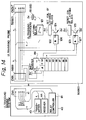
- Fig. 4 shows the construction of one embodiment of the diagnostic sonography system according to the present invention.
- the reference numeral 40 indicates an ultrasound imaging system having a plug type connector (CNA) 41, instead of the previously-mentioned connecting device, to which ultrasound probes 50 and 60 can be connected in series, and a monitor 42 that analyses the information supplied through the plug connector 41 from the probes 50 and 60.
- CNA plug type connector
- the monitor 42 comprises a transmission circuit 43 that produces an electric signal for the transmission of an ultrasound into the examinee, a reception circuit 44 that receives and amplifies an electric signal derived from conversion of the ultrasound reflected from inside the examinee, a thermal monitoring circuit 45 that detects the temperature of a probe, a probe information interface 46 that, upon receiving set probe information, reads the information, such as type, shape, etc., on the probe 50 or 60 currently connected, a display drive 47 that delivers a signal indicating that the probe 50 or 60 is being used, a number-of-probes detector 48 that detects the number of probes 50 or 60 connected to the plug connector 41, a cap detector 49 that detects that a blind cap is attached directly to the plug connector 41 or to the probe 50 or 60 connected to the plug connector 41, and a controller 42a that designates various kinds of control to the probe 50 or 60.
- the probe 50 (or 60) comprises a receptacle type connector (CNIN) 51 (or 61), as the first connecting device, which is to be fitted into the plug connector 41 of the ultrasound imaging system 40, a plug connector (CNOUT) 52 (or 62), instead of the previously-mentioned second connecting device, which is to be fitted onto the receptacle connector 51 (or 61), an input/output connector 53 (or 63) that sets an electrical connection with the ultrasound imaging system 40, a probe check signal generation circuit 54 (or 64) forming a circuit of a constant resistance, a plurality of, for example, 64 or 128, ultrasound transducer elements 55 (or 65) in a group, that form together an electroacoustic or ultrasound transducer, a thermosensor 56 (or 66) made of a thermistor, a probe coder 57 (or 67), instead of the previously-mentioned probe information setting means, to set the probe information such as frequency
- Such probe information or codes are analyzed in the probe information interface 46 of the ultrasound imaging system to discriminate the structure and performance of the ultrasound probe connected.
- the input/output connector 53 (or 63) comprises a switch controller 53a (or 63a) that, upon receiving a select signal from the ultrasound imaging system 40, controls the switching of electrical connection between the ultrasound imaging system 40 and ultrasound probe 50 (or 60), and an on/off switch 53b (or 63b) that turns on and off the electrical connection under the control of the switch controller 53a (or 63a).
- the cap 70 is provided with a receptacle connector 70a that is to be fitted directly into the plug connector 41 or into the plug connector 52 of 62 of the probe 50 or 60 connected to the plug connector 41, and short-circuits each connecting a terminal at the opposite end of the connecting opening of the receptacle connector 70a.
- the cap 70 has a body that covers the receptacle connector 70a and is made of an electrically conductive material for electromagnetic shielding, and has the entire outer surface, except for the connector opening, covered with an electrically insulative film for electrical insulation from the inner surface.
- the receptacle connector 51 of the probe 50 is connected to the single plug connector 41 of the ultrasound imaging system 40 and the receptacle connector 61 is connected to the plug connector 52 of the probe 50, thus the plurality of probes 50 and 60 are connected to the single connector (plug type) of the ultrasound imaging system 40.
- the connection of the cap 70 with the plug connector 62 of the probe protects the circuit end and shuts off any external noise.
- the probe coder 57 or 67 sends to the probe information interface 46 detailed information on the probe 50 or 60 connected to the ultrasound imaging system 40, and thereafter a signal is sent from the ultrasound imaging system 40 to put into operation the input/output connector 53 or 63 of the probe 50 or 60 that is to be used, thus causing the switch controller 53a or 63a to activate the switch 53b or 63b, thereby providing an electrical connection between the ultrasound imaging system 40 and the desired probe 50 or 60.
- the ultrasound imaging system 40 When the ultrasound imaging system 40 and the probe 50 or 60 is thus electrically connected to each other, the ultrasound imaging system 40 generates a transmission signal to drive the group of ultrasound transducers 55 or 65, which will generate an ultrasound. At this time, the temperature measured by the thermosensor 56 or 66 is sent to the thermal monitoring circuit 45 to monitor whether if the ultrasound is generated in a normal range of probe temperature.
- a set-status display 58 or 68 may be provided to emit light so that the operator knows which probe 50 or 60 is in operation.
- the receptacle connector 51 is connected to the single plug connector 41 of the ultrasound imaging system 40 and the receptacle connector 61 of the probe 60 is connected to the plug connector 52 of the probe 50, thereby permitting the connection of a plurality of probes 50 and 60 to the single (plug) connector 41 of the ultrasound imaging system 40.
- connection of the cap 70 to the plug connector of the probe 60 protects the circuit end and shuts off any external noise.
- the input/output connector 53 or 63 is activated to turn on the switch 53b or 63b by means of the switch controller 53a or 63a, thereby electrically connecting the probe 50 or 60 to the ultrasound imaging system 40.
- a necessary prove can freely by selected from the probes 50 and 60 connected to the same plug connector 41 of the ultrasound imaging system 40.
- probe information is sent from the probe coder 57 or 67 and probe temperature measured by the thermosensor 56 or 66 is supplied.
- probe temperature measured by the thermosensor 56 or 66 is supplied.
- the set-status display 58 or 68 emits light so that the operator will easily know which is in operation, 50 or 60. Hence, it is easy to select a probe and diagnose the examinee by using a desired probe 50 or 60.
- the ultrasound imaging system 40 has a relay controller 81, instead of the previously-mentioned controller 42a.
- the ultrasound probe 50 or 60 has provided in the input/output connector 53 (or 63) thereof, which selects an electrically connected-status, a switch 82 and a coil 83 of normally off electromagnetic relays (stable relays), instead of the previously-described switch 53b (or 63b), and a circuit formed by a transistor 84, instead of the previously-mentioned switch controller 53a (or 63a), which excites the coil 83 of the electromagnetic relays, an AND circuit that turns on the transistor 84 and a shift register 86 that supplies a signal to the AND circuit 85.
- a data signal DT including a probe designation number and clock signal CK are supplied to the probe 50 or 60 from the relay controller 81 of the ultrasound imaging system 40.
- a high level signal is delivered at the output terminal QA of the shift register 86 (provided in the corresponding probe) turned on with the signals DT and CK and an enable signal EN is supplied to the probe, both the high level signals QA and EN are ANDed by the AND circuit 85 to provide the result as a high level signal Y that will turn on the transistor 84 and excite the coil 83 of the electromagnetic relays so that the switch 82 is closed.
- the ultrasound transducers 55 (or 65) are excited to make an electroacoustic transducing for the generation of an ultrasound.
- FIG. 8 A variant of the probe information transmission system will be explained with reference to Fig. 8.
- a combination of a three-state buffer and pin board is adopted.
- the ultrasound imaging system 40 is supplied with a clock signal CK and control bit signal D9 from an 8-bit data line (for transmission of data signals D1 to D8) grounded by means of a resistor 91 and the probe information interface 46, and delivers the data signals D1 to D8 to the data line.
- the probe 50 (or 60) is provided with a flip-flop 91, instead of the previously-mentioned input/output connector 53.
- the flip-flop 92 is supplied with a clock signal CK and control bit signal D9.
- the flip-flop 92 is so arranged that when an initial clock signal CK is supplied, its output signal Q takes a low level and when a second clock signal CK is supplied, the output signal takes a high level.
- a three-state buffer 93 is provided that is supplied at the two enable terminals EN with the output signal Q of the flip-flop 92 to input and output a hold data.
- a pin board 94 instead of the previously-described probe coder 57 (or 67), to set probe information that is to be stored in the three-state buffer 93, and as many resistors 95 as the pins interposed between one end of the pin board 94 and the power source.
- the pin board 94 sets the necessary 8-bit information taking as "1" the position where a short-circuit bar 94a is inserted and as "0" the position where no such short-circuit bar is inserted.
- Such 8-bit information namely, information on the ultrasound probe in consideration, is read out once to the buffer 93 and the result is transmitted to the ultrasound imaging system 40.
- the flip-flop 92 when the control bit signal D9 takes a low level while the clock signal CK takes a high level, the flip-flop 92 delivers an output signal Q at the same low level as the control signal D9 so that the three-state buffer 93 becomes active and probe information held after being supplied from the pin board 94 is delivered.
- the flip-flop 92 delivers an output signal Q at the same high level as the control bit signal D9 and a signal no longer delivered from the three-state buffer 93 so that the low level will result from grounding via the resistor 91 of the ultrasound imaging system 40.
- the thermal monitoring system uses a thermistor that has a negative resistance-thermal characteristic.
- This thermal monitoring system has a thermal monitoring circuit that comprises a resistor and an operational amplifier in combination.
- a thermal protection circuit 100 formed instead of the previously-described thermal monitoring circuit 45 of the ultrasound imaging system 40, there is provided a resistor (R60) 101 between a wire connected to the thermistor 56 (66) of the probe 50 (60) and the power source Vcc, and a wire between the thermistor 56 (66) and resistor 101 is branched and connected to the inversion input terminal (-) of an operational amplifier 102.
- Two resistors 103 and 104 having different resistances are connected in series between the power source Vcc and ground potential (0V) and a wire between the resistor (R61) 103 and resistor (R62) 014 is branched and connected to the non-inversion input terminal (+) of the operational amplifier 102.
- the inversion input terminal (-) and output terminal of the operational amplifier 102 are wired to each other via a variable resistor (RV1) 105.
- the output terminal of the operational amplifier 102 is connected to the inversion input terminal (-) of a comparator 106.
- variable resistor (RV2) 107 of which the variable terminal is connected to the non-inversion input terminal (+) of an operational amplifier 108.
- the inversion input terminal (-) of the operational amplifier 108 is connected to the output terminal thereof.
- the output terminal of the operational amplifier 108 is connected to the non-inversion input terminal (+) of the comparator 106 by means of a resistor (R67) 109.
- the non-inversion input terminal (+) of the comparator 106 is connected to the output terminal thereof by means of a resistor (R68) 110.
- resistor (R69) 111 between the output terminal of the comparator 106 and power source Vcc.
- the thermistor 56 (or 66) incorporated in the probe 50 (60) has a reduced resistance. As shown in Fig. 10, the characteristic of output voltage (V2) vs. resistance of thermistor 56 (or 66) is negative.
- a hysteresis is set for the characteristic of the output voltage (Vout) vs. temperature measured by the thermistor 56 (or 66) shown in Fig. 11. If the temperature rises higher than predetermined, the output voltage (Vout) goes to a low level. When the temperature falls lower than predetermined, the output voltage (Vout) goes up to a high level, whereby chattering phenomena of the temperature control is prevented.
- the thermal protection offered by this circuit is such that when the input signal V2 to the inversion input terminal (-) of the comparator 106 is larger than the input signal V1 to the non-inversion input terminal (+), the output signal from the output terminal goes lower so that the ultrasound transducers 55 (or 65) detect when the temperature has risen above the predetermined temperature and stops transmission of the electric signal that drives the probe. Thus, the probe is inhibited from generating more ultrasound.
- a system to detect the number of probes that has a measuring power source (-Vmm) provided in the ultrasound imaging system 40 as shown in Fig. 12 will be described.
- amplification circuit 112 on one of the transmission lines of the number-of-probes system.
- an operational amplifier 114 of which the non-inversion input terminal (+) is grounded and the inversion input terminal (-) is connected to the output terminal thereof by means of a resistor (R2) 113.
- a negative power source (-Vmm) is connected to the other transmission lines of the number-of-probes detecting system connected to the plug connector 41.
- a resistor (R1) 115 (or 116) is connected between the number-of-probes detecting buses.
- the resistor 115 is an example of the probe check signal generator used in the number-of-probes detecting system connected to the ultrasound imaging system 40 according to the present invention.
- resistors having the same resistance are provided in the respective ultrasound probes. More particularly, one ultrasound probe develops a voltage for one resistor, so that by checking the overall voltage drop, it is possible to know how many probes are connected to the ultrasound imaging system 40.
- the output voltage of the operational amplifier 114 is proportional to the number of probes connected to the ultrasound imaging system 40, the number of probes connected can be easily known by measuring the output voltage of the comparison circuit 112 in the number-of-probes detector 112. This is a very simple way to know the number of connected probes and can be done even with the cap 70 not attached.
- the reference numeral 121 indicates a switch for the latching relays, 122 a set coil of the latching relays, and 123 a reset coil of the latching relays.
- the set coil 122 and reset coil 123 of the latching relays are excited by transistors 124 and 125, respectively, which are turned on with output signals (transistor ON signal) from AND circuits 126 and 127, respectively.
- the AND circuit 126 delivers a high level signal (transistor ON signal)
- the AND circuit 127 delivers a high level signal (transistor ON signal).
- Other arrangements of the probe connecting system are similar to those in the first variant.
- the relay controller 81 delivers a clock signal CK and a data signal DT including a probe designation number
- the output signal delivered at the output terminal QA of the shift register 86 takes a high level at the second rise of the clock signal CK.
- a control signal (enable signal) E1 is delivered from the relay controller 81
- the AND circuit 126 supplies a transistor on signal (Y1), the set coil 122 is excited and thus the switch 121 is closed.
- the ultrasound transducers 55 (or 65) produces an ultrasound.
- a high level signal is delivered at the output terminal QB of the shift register 86 synchronously with the rise of clock signal, and a control signal (enable signal) E2 is delivered from the relay controller 81.
- the AND circuit 127 generates a transistor ON signal (Y2), the reset coil 123 is excited and the switch 121 is opened.
- the ultrasound transducers 55 or 65 are stopped from generating ultrasound. Since it is necessary to supply a current only for operating the latching relays, the power consumption by the coil is very small.
- the probe information transmission system comprises a shift register 128 that can store each bit of an 8-bit data and shifts the stored data individually toward the output terminal QH by delivering one bit at the output terminal QH each time a clock signal CK is supplied, a pin board 129 so connected as to supply one bit into each storage area of the shift register 128, and a power source (5V) connected to each bit setting terminal of the pin board 129 by means of a resistor 130.
- the output terminal QH of the shift register 128 is connected to the transmission terminal for data signal DT of the receptacle connector 51 (or 61), the transmission terminal for data signal DT of the plug connector 52 (or 62) is connected to the first storage area (input terminals 1D and 3D) of the shift register 128, and the transmission line (interconnecting wire) is branched at the mid point and grounded by means of a resistor 131.
- the resistance of the resistor 131 is sufficiently high for transmission of a digital signal on the transmission line between the plug connector 52 (or 62) and shift register 128.
- Concerning the probe information in the probe information transmission system insertion of at least one short-circuit bar 129a into the pin board 129 of the probe 50 (or 60) represents 8-bit data other than zero, and all 8 bits being zeros means that no probe is connected.
- the output from the shift register at the probe 60 is connected to the first storage area of the shift register 128 at the probe 50 by means of the plug connector 52.
- the probe information on the probe 50 is supplied to the probe information interface 46 and with the subsequent 8 clock signals CK, the probe information on the probe 60 is supplied to the probe information interface 46 through the shift register 128 at the probe 50.
- the thermal monitoring system uses a thermistor that has a negative resistance-thermal characteristic.
- This thermal monitoring system has a thermal monitoring circuit provided in the probe.
- the ultrasound imaging system 40 has a thermal data line (for transmission of thermal data TH) grounded by means of a resistor 132 and delivers clock signal CK and control bit signal DT at the probe information interface 46. Also it has a thermal monitoring receiver 133, instead of the previously-mentioned thermal monitor, which receives thermal data detected at the probe 50 (or 60).
- the probe 50 (or 60) comprises a flip-flop 92, instead of the previously-mentioned input/output connector 53 (or 63), which when supplied with clock signal CK and control bit signal DT, delivers a low level output signal Q with the first clock signal CK and a high level output signal Q with the second clock signal CK, a switch controller 134a that opens a switch 134b when the output signal Q from the flip-flop 92 takes a high level, the switch 134b that opens and closes under the control of the switch controller 134a, a thermistor 135, instead of the previously-described thermosensor 56 (or 66), which has a negative resistance-temperature characteristic, an amplifier 137, in place of the thermal monitoring circuit 136, which amplifies the output signal from the thermistor 135, and a DC source 138 that supplies a current to the amplifier 137 and thermistor 135.
- the flip-flop 92 delivers an output signal Q at the same level as the control bit signal DT, the switch 134b is closed under control of the switch controller 134a to which the low level signal has been supplied, thereby transmitting to the thermal monitoring receiver 133 at the ultrasound imaging system 40 the thermal data TH measured by the thermistor 135 and amplified by the amplifier 137.
- a variant of the number-of-probes detecting system will be described that has a current source (Ipp) provided at the ultrasound imaging system 40 as shown in Fig. 20.
- a current source connected to a branch of one of the transmission lines of the number-of-probes detecting system, with the other transmission line connected to the plug connector 41 being grounded.
- Ipp current source
- the resistors 141 and 142 are of the same resistance.
- the circuitry of this number-of-probes detecting system is formed by connecting the receptacle connector 51 (or 61) of the probe 50 (or 60) to the plug connector 41 of the ultrasound imaging system 40 and the receptacle connector 70a of the cap 70 to the plug connector 52 (or 62) of the probe, or alternately by further connecting the receptacle connector 61 (or 51) of the other probe 60 (or 50) to the plug connector 52 (or 62) of the probe and the receptacle connector 70a of the cap 70 to the plug connector 62 (or 52) of the probe.
- the voltage rises in proportion to the constant current (Ipp) from the power source (Vpp) and as the product of the current (Ipp) and the number of probes 50 (or 60) to which the resistors 141 and 142 are connected, which assures easy confirmation of the number of probes connected.
- the circuit of the number-of-probes detecting system is not formed, no current is carried and the resistance becomes infinitely higher unless the cap 70 is attached. Thus the presence or absence of the cap 70 is easily known.
- the embodiment of the present invention can be varied and modified in various manners for a highly efficient ultrasound study, for a variable number of probes connected and for a simplified construction and preliminary operation of the equipment.
- the connecting device 13a (or 13b) of the ultrasound probe 11a (or 11b) is connected as fitted to the single connecting device 10a of the ultrasound imaging system 10 and the connecting device 13b (or 13a) of the other ultrasound probe 11b (or 11a) is connected as fitted to the other connecting device 14a (or 14b) of the ultrasound probe 11a (or 11b).
- a plurality of ultrasound probes 11a and 11b can be connected to the single connecting device 10a of the ultrasound imaging system 40. Namely, a necessary number of ultrasound probes can be connected to the ultrasound imaging system 40 before starting an ultrasound study. Thus, since it is unnecessary to replace the probe in the middle of the ultrasound study, the diagnosis can be done very easily and efficiently.
- the transducer 16a (or 16b) of an ultrasound probe 11a (or 11b) to be used is connected to the ultrasound imaging system 10. So one of the plurality of ultrasound probes 11a or 11b connected to the single connecting device 10a of the ultrasound imaging system 40 can be used as selected. No probe selecting device has to be provided at the ultrasound imaging system 10.
- the equipment construction can be considerably simplified, equipment operability during an ultrasound study can be greatly improved and the time for ultrasound diagnosis can be effectively shortened.
- the probe information set at the transducer 16a (16b) in an ultrasound probe 11a or 11b of which the connection is indicated can be used for correct electroacoustic transducing of diagnostic ultrasound when the probe temperature is measured within a predetermined range. Therefore, even when a plurality of ultrasound probes 11a and 11b are connected to the same connecting device 10a of the ultrasound imaging system 10, a desired probe cannot be mistaken for any other probe, thus ensuring a correct and rapid ultrasound diagnosis.
- a notice from each number-of-probes informing means 26 is received by the number-of-probes detector 36 of the ultrasound imaging system 10 to confirm the number of ultrasound probes 11a or 11b connected to the same connecting device 10a of the ultrasound imaging system 10, thereby permitting the operator to easily know a plurality of ultrasound probes connected.
- the blind cap 12 can be attached to the connecting device 10a of the ultrasound imaging system 10 or the connecting device 14a or 14b of the ultrasound probe 11a or 11b.
- the connecting device 10a, 14a or 14b open-circuited can be avoided thereby eliminating a cause of damage to the equipment or mistaking of an ultrasound probe during ultrasound diagnosis.
Landscapes
- Physics & Mathematics (AREA)
- Engineering & Computer Science (AREA)
- Radar, Positioning & Navigation (AREA)
- Remote Sensing (AREA)
- Acoustics & Sound (AREA)
- Computer Networks & Wireless Communication (AREA)
- General Physics & Mathematics (AREA)
- Ultra Sonic Daignosis Equipment (AREA)
- Investigating Or Analyzing Materials By The Use Of Ultrasonic Waves (AREA)
Applications Claiming Priority (2)
| Application Number | Priority Date | Filing Date | Title |
|---|---|---|---|
| JP3207891A JP2683966B2 (ja) | 1991-08-20 | 1991-08-20 | スタック接続方式の超音波プローブおよび超音波診断装置ならびに超音波診断システム |
| JP207891/91 | 1991-08-20 |
Publications (2)
| Publication Number | Publication Date |
|---|---|
| EP0528693A1 true EP0528693A1 (de) | 1993-02-24 |
| EP0528693B1 EP0528693B1 (de) | 1997-07-30 |
Family
ID=16547283
Family Applications (1)
| Application Number | Title | Priority Date | Filing Date |
|---|---|---|---|
| EP92307611A Expired - Lifetime EP0528693B1 (de) | 1991-08-20 | 1992-08-20 | Schallabbildung-Diagnoseneinrichtung mit mehreren Ultraschallproben |
Country Status (4)
| Country | Link |
|---|---|
| US (1) | US5318027A (de) |
| EP (1) | EP0528693B1 (de) |
| JP (1) | JP2683966B2 (de) |
| DE (1) | DE69221227T2 (de) |
Cited By (2)
| Publication number | Priority date | Publication date | Assignee | Title |
|---|---|---|---|---|
| US20160030003A1 (en) * | 2013-04-16 | 2016-02-04 | Shenzhen Mindray Bio-Medical Electronics Co., Ltd. | Ultrasonic diagnostic device and method for supporting synchronous scanning with multiple probes |
| EP3056152A1 (de) * | 2015-02-13 | 2016-08-17 | Samsung Medison Co., Ltd. | Röntgenstrahlabbildungsvorrichtung und verfahren zur steuerung davon |
Families Citing this family (33)
| Publication number | Priority date | Publication date | Assignee | Title |
|---|---|---|---|---|
| US5673698A (en) * | 1994-04-21 | 1997-10-07 | Hitachi Medical Corporation | Multichannel ultrasonic diagnosis apparatus |
| JPH07289553A (ja) * | 1994-04-22 | 1995-11-07 | Hitachi Medical Corp | 超音波断層装置 |
| US5505203A (en) * | 1994-11-23 | 1996-04-09 | General Electric Company | Method and apparatus for automatic transducer selection in ultrasound imaging system |
| US5744555A (en) * | 1994-11-25 | 1998-04-28 | Eastman Chemical Company | Process for the synthesis of elastomeric polypropylene |
| US5615678A (en) * | 1994-11-25 | 1997-04-01 | General Electric Company | Integral auto-selecting yoke/transducer connector for ultrasound transducer probe |
| US5544660A (en) * | 1995-03-30 | 1996-08-13 | Boston Scientific Corp. | Acoustic imaging catheter and method of operation |
| US5611343A (en) * | 1995-04-05 | 1997-03-18 | Loral Aerospace Corp. | High resolution three-dimensional ultrasound imaging |
| US5776065A (en) * | 1996-09-18 | 1998-07-07 | Acuson Corporation | Apparatus and method for controlling an ultrasound transducer array |
| US5882310A (en) * | 1997-12-01 | 1999-03-16 | Acuson Corporation | Ultrasound transducer connector and multiport imaging system receptacle arrangement |
| US6811902B2 (en) * | 2001-07-31 | 2004-11-02 | Delphi Technologies, Inc. | Battery pack having improved battery cell terminal configuration |
| US6500126B1 (en) * | 2001-12-20 | 2002-12-31 | Koninklijke Philips Electronics N.V. | Ultrasound system transducer adapter |
| US7534211B2 (en) * | 2002-03-29 | 2009-05-19 | Sonosite, Inc. | Modular apparatus for diagnostic ultrasound |
| US6629928B1 (en) * | 2002-11-08 | 2003-10-07 | Koninklijke Philips Electronics N.V. | Modular transducer connection system |
| US7591786B2 (en) * | 2003-01-31 | 2009-09-22 | Sonosite, Inc. | Dock for connecting peripheral devices to a modular diagnostic ultrasound apparatus |
| JP3669990B2 (ja) * | 2003-02-12 | 2005-07-13 | ファナック株式会社 | インバータ装置の接地方法及びインバータ装置 |
| US20050113690A1 (en) * | 2003-11-25 | 2005-05-26 | Nahi Halmann | Methods and systems for providing portable device extended resources |
| WO2005053664A2 (en) | 2003-11-26 | 2005-06-16 | Teratech Corporation | Modular portable ultrasound systems |
| EP1787586B1 (de) * | 2004-08-31 | 2008-06-25 | Kabushiki Kaisha Toshiba | Untersuchungsapparat mit Ultraschallsonde, Ultraschalluntersuchungsgerät und Untersuchungsmethode mit einer Ultraschallsonde |
| US20070232907A1 (en) * | 2006-04-03 | 2007-10-04 | Laurent Pelissier | Methods and systems for configuring ultrasound systems for ultrasound examinations |
| US7505363B2 (en) | 2006-04-10 | 2009-03-17 | Airmar Technology Corporation | Automatic switch for marine sounders |
| JP2008061938A (ja) * | 2006-09-11 | 2008-03-21 | Toshiba Corp | 超音波プローブ、超音波診断装置及び超音波プローブ監視システム |
| US8600299B2 (en) * | 2006-11-10 | 2013-12-03 | Siemens Medical Solutions Usa, Inc. | Transducer array imaging system |
| US9295444B2 (en) | 2006-11-10 | 2016-03-29 | Siemens Medical Solutions Usa, Inc. | Transducer array imaging system |
| US7984651B2 (en) * | 2006-11-10 | 2011-07-26 | Penrith Corporation | Transducer array imaging system |
| US8143898B1 (en) | 2007-04-06 | 2012-03-27 | Unisyn Medical Technologies, Inc. | Systems and methods for reconfiguring an ultrasound device |
| US8033174B2 (en) * | 2007-09-07 | 2011-10-11 | Medison Co. Ltd. | Ultrasound diagnostic system |
| JP2009219794A (ja) * | 2008-03-18 | 2009-10-01 | Olympus Medical Systems Corp | 超音波診断装置 |
| JP5501585B2 (ja) * | 2008-08-19 | 2014-05-21 | ジーイー・メディカル・システムズ・グローバル・テクノロジー・カンパニー・エルエルシー | 超音波診断装置及びアダプタ |
| KR101263831B1 (ko) * | 2011-09-19 | 2013-05-13 | 삼성메디슨 주식회사 | 진단영상 생성장치, 프로브, 프로브를 제어하는 방법 및 진단영상을 생성하는 방법 |
| JP6024120B2 (ja) * | 2012-02-24 | 2016-11-09 | セイコーエプソン株式会社 | 超音波プローブ、プローブヘッド、電子機器及び診断装置 |
| DE102012111427A1 (de) | 2012-11-26 | 2014-05-28 | Endress + Hauser Flowtec Ag | Feldgerät, insbesondere Ultraschall-Durchflussmessgerät |
| DE102013101158A1 (de) * | 2013-02-06 | 2014-08-07 | Karl Storz Gmbh & Co. Kg | Medizinische Vorrichtung und Verfahren zum Konfigurieren eines medizinischen Systems |
| US10816638B2 (en) * | 2014-09-16 | 2020-10-27 | Symbol Technologies, Llc | Ultrasonic locationing interleaved with alternate audio functions |
Citations (1)
| Publication number | Priority date | Publication date | Assignee | Title |
|---|---|---|---|---|
| DE3624668A1 (de) * | 1985-07-23 | 1987-02-05 | Toshiba Kawasaki Kk | Ultraschall-abbildungsgeraet |
Family Cites Families (12)
| Publication number | Priority date | Publication date | Assignee | Title |
|---|---|---|---|---|
| JPS5615734A (en) * | 1979-07-20 | 1981-02-16 | Tokyo Shibaura Electric Co | Ultrasonic diagnosing device |
| JPS6116658U (ja) * | 1984-07-03 | 1986-01-30 | 三菱電機株式会社 | 優先順位移行装置 |
| JPH0734797B2 (ja) * | 1986-12-18 | 1995-04-19 | 株式会社日立メデイコ | 超音波診断装置 |
| JPS63242246A (ja) * | 1987-03-31 | 1988-10-07 | 株式会社 日立メデイコ | 体腔内用超音波探触子 |
| JPH01254150A (ja) * | 1988-04-04 | 1989-10-11 | Fujitsu Ltd | 超音波診断装置 |
| JPH0215459A (ja) * | 1988-07-04 | 1990-01-19 | Toshiba Corp | ディスク再生機の接続装置 |
| JPH066805Y2 (ja) * | 1988-08-26 | 1994-02-23 | 横河メディカルシステム株式会社 | 超音波診断装置 |
| JPH02201679A (ja) * | 1989-01-31 | 1990-08-09 | Toshiba Corp | システム構成認識方式 |
| JPH02116345U (de) * | 1989-03-01 | 1990-09-18 | ||
| JPH0382454A (ja) * | 1989-08-28 | 1991-04-08 | Fujitsu Ltd | 超音波診断装置 |
| JPH03182236A (ja) * | 1989-12-11 | 1991-08-08 | Aloka Co Ltd | 超音波診断装置 |
| US5205175A (en) * | 1990-02-27 | 1993-04-27 | Acoustic Imaging Technologies Corporation | Multiple transducer selector |
-
1991
- 1991-08-20 JP JP3207891A patent/JP2683966B2/ja not_active Expired - Fee Related
-
1992
- 1992-08-20 US US07/932,965 patent/US5318027A/en not_active Expired - Lifetime
- 1992-08-20 EP EP92307611A patent/EP0528693B1/de not_active Expired - Lifetime
- 1992-08-20 DE DE69221227T patent/DE69221227T2/de not_active Expired - Fee Related
Patent Citations (1)
| Publication number | Priority date | Publication date | Assignee | Title |
|---|---|---|---|---|
| DE3624668A1 (de) * | 1985-07-23 | 1987-02-05 | Toshiba Kawasaki Kk | Ultraschall-abbildungsgeraet |
Non-Patent Citations (2)
| Title |
|---|
| JOURNAL OF PHYSICS E ; SCIENTIFIC INSTRUMENTS, vol. 9, no. 3, March 1976, BRISTOL GB, pages 153 - 162 C.R.HILL, 'Ultrasonic imaging' * |
| ULTRASONICS, March 1965, BERLIN DE, pages 18 - 21 W. BUSCHMANN, 'new equipment and transducers for ophthalmic diagnosis' * |
Cited By (4)
| Publication number | Priority date | Publication date | Assignee | Title |
|---|---|---|---|---|
| US20160030003A1 (en) * | 2013-04-16 | 2016-02-04 | Shenzhen Mindray Bio-Medical Electronics Co., Ltd. | Ultrasonic diagnostic device and method for supporting synchronous scanning with multiple probes |
| EP3056152A1 (de) * | 2015-02-13 | 2016-08-17 | Samsung Medison Co., Ltd. | Röntgenstrahlabbildungsvorrichtung und verfahren zur steuerung davon |
| KR20160099820A (ko) * | 2015-02-13 | 2016-08-23 | 삼성메디슨 주식회사 | 초음파 영상 장치 및 초음파 영상 장치의 제어 방법 |
| US10094807B2 (en) | 2015-02-13 | 2018-10-09 | Samsung Medison Co., Ltd. | Ultrasound imaging apparatus and method of controlling the same |
Also Published As
| Publication number | Publication date |
|---|---|
| DE69221227T2 (de) | 1997-11-27 |
| EP0528693B1 (de) | 1997-07-30 |
| US5318027A (en) | 1994-06-07 |
| JPH0542143A (ja) | 1993-02-23 |
| JP2683966B2 (ja) | 1997-12-03 |
| DE69221227D1 (de) | 1997-09-04 |
Similar Documents
| Publication | Publication Date | Title |
|---|---|---|
| US5318027A (en) | Stack-connectable ultrasound probe, ultrasound imaging system and diagnostic sonography system | |
| US6270463B1 (en) | System and method for measuring temperature in a strong electromagnetic field | |
| JP3592341B2 (ja) | 超音波走査ヘッド | |
| EP1543776B1 (de) | Ultraschallgerät | |
| EP1900327A1 (de) | Ultraschallsonde, Ultraschalldiagnosevorrichtung, Ultraschallsondenüberwachungssystem und Verfahren zur Verwaltung des Zustands der Ultraschallsonde | |
| US5251631A (en) | Ultrasonic imaging apparatus | |
| US8033174B2 (en) | Ultrasound diagnostic system | |
| EP0501819B1 (de) | Ultraschall Diagnosegerät | |
| US5509421A (en) | System, with sensor positioning indicator, for monitoring a biological signal | |
| JP3967429B2 (ja) | 超音波診断装置 | |
| JP4751147B2 (ja) | 超音波プローブ診断装置、超音波診断装置および超音波プローブ診断方法 | |
| JPS6222638A (ja) | 超音波探触子接続用アダプタ | |
| KR101031501B1 (ko) | 초음파 진단장치의 프로브 접속확인장치 | |
| JP4632527B2 (ja) | 超音波プローブおよび超音波診断装置 | |
| US20190343483A1 (en) | Systems, methods, and apparatuses for fluid ingress detection for ultrasound transducers | |
| KR101510679B1 (ko) | 초음파 프로브 | |
| US20210295978A1 (en) | System and Method for Controlling Operability of Multiple Medical Devices | |
| US11399802B2 (en) | Methods and ultrasound apparatus | |
| JPH0312137A (ja) | 超音波トランスポンダー及び超音波診断装置 | |
| JPS61181445A (ja) | 超音波診断装置 | |
| JPS5814219B2 (ja) | 体腔插入プロ−ブを用いた超音波診断装置のプロ−ブ位置検出器 | |
| JPS63234956A (ja) | 体腔内用超音波探触子 | |
| JPH0793929B2 (ja) | 超音波診断装置 | |
| JP3699916B2 (ja) | 超音波診断装置 | |
| JP2000037383A (ja) | 超音波診断装置 |
Legal Events
| Date | Code | Title | Description |
|---|---|---|---|
| PUAI | Public reference made under article 153(3) epc to a published international application that has entered the european phase |
Free format text: ORIGINAL CODE: 0009012 |
|
| AK | Designated contracting states |
Kind code of ref document: A1 Designated state(s): DE FR |
|
| 17P | Request for examination filed |
Effective date: 19930430 |
|
| 17Q | First examination report despatched |
Effective date: 19950627 |
|
| GRAG | Despatch of communication of intention to grant |
Free format text: ORIGINAL CODE: EPIDOS AGRA |
|
| GRAH | Despatch of communication of intention to grant a patent |
Free format text: ORIGINAL CODE: EPIDOS IGRA |
|
| GRAH | Despatch of communication of intention to grant a patent |
Free format text: ORIGINAL CODE: EPIDOS IGRA |
|
| GRAA | (expected) grant |
Free format text: ORIGINAL CODE: 0009210 |
|
| AK | Designated contracting states |
Kind code of ref document: B1 Designated state(s): DE FR |
|
| REF | Corresponds to: |
Ref document number: 69221227 Country of ref document: DE Date of ref document: 19970904 |
|
| ET | Fr: translation filed | ||
| PLBE | No opposition filed within time limit |
Free format text: ORIGINAL CODE: 0009261 |
|
| STAA | Information on the status of an ep patent application or granted ep patent |
Free format text: STATUS: NO OPPOSITION FILED WITHIN TIME LIMIT |
|
| 26N | No opposition filed | ||
| REG | Reference to a national code |
Ref country code: FR Ref legal event code: TP |
|
| PGFP | Annual fee paid to national office [announced via postgrant information from national office to epo] |
Ref country code: FR Payment date: 20050809 Year of fee payment: 14 |
|
| PGFP | Annual fee paid to national office [announced via postgrant information from national office to epo] |
Ref country code: DE Payment date: 20050818 Year of fee payment: 14 |
|
| PG25 | Lapsed in a contracting state [announced via postgrant information from national office to epo] |
Ref country code: DE Free format text: LAPSE BECAUSE OF NON-PAYMENT OF DUE FEES Effective date: 20070301 |
|
| REG | Reference to a national code |
Ref country code: FR Ref legal event code: ST Effective date: 20070430 |
|
| PG25 | Lapsed in a contracting state [announced via postgrant information from national office to epo] |
Ref country code: FR Free format text: LAPSE BECAUSE OF NON-PAYMENT OF DUE FEES Effective date: 20060831 |