EP0526916A2 - Image-forming machine - Google Patents
Image-forming machine Download PDFInfo
- Publication number
- EP0526916A2 EP0526916A2 EP92118353A EP92118353A EP0526916A2 EP 0526916 A2 EP0526916 A2 EP 0526916A2 EP 92118353 A EP92118353 A EP 92118353A EP 92118353 A EP92118353 A EP 92118353A EP 0526916 A2 EP0526916 A2 EP 0526916A2
- Authority
- EP
- European Patent Office
- Prior art keywords
- feed
- opening
- housing
- introduction opening
- main body
- Prior art date
- Legal status (The legal status is an assumption and is not a legal conclusion. Google has not performed a legal analysis and makes no representation as to the accuracy of the status listed.)
- Withdrawn
Links
Images

Classifications
-
- G—PHYSICS
- G06—COMPUTING OR CALCULATING; COUNTING
- G06K—GRAPHICAL DATA READING; PRESENTATION OF DATA; RECORD CARRIERS; HANDLING RECORD CARRIERS
- G06K15/00—Arrangements for producing a permanent visual presentation of the output data, e.g. computer output printers
-
- G—PHYSICS
- G03—PHOTOGRAPHY; CINEMATOGRAPHY; ANALOGOUS TECHNIQUES USING WAVES OTHER THAN OPTICAL WAVES; ELECTROGRAPHY; HOLOGRAPHY
- G03G—ELECTROGRAPHY; ELECTROPHOTOGRAPHY; MAGNETOGRAPHY
- G03G15/00—Apparatus for electrographic processes using a charge pattern
- G03G15/65—Apparatus which relate to the handling of copy material
- G03G15/6502—Supplying of sheet copy material; Cassettes therefor
- G03G15/6514—Manual supply devices
-
- G—PHYSICS
- G03—PHOTOGRAPHY; CINEMATOGRAPHY; ANALOGOUS TECHNIQUES USING WAVES OTHER THAN OPTICAL WAVES; ELECTROGRAPHY; HOLOGRAPHY
- G03G—ELECTROGRAPHY; ELECTROPHOTOGRAPHY; MAGNETOGRAPHY
- G03G15/00—Apparatus for electrographic processes using a charge pattern
- G03G15/22—Apparatus for electrographic processes using a charge pattern involving the combination of more than one step according to groups G03G13/02 - G03G13/20
- G03G15/23—Apparatus for electrographic processes using a charge pattern involving the combination of more than one step according to groups G03G13/02 - G03G13/20 specially adapted for copying both sides of an original or for copying on both sides of a recording or image-receiving material
- G03G15/231—Arrangements for copying on both sides of a recording or image-receiving material
- G03G15/232—Arrangements for copying on both sides of a recording or image-receiving material using a single reusable electrographic recording member
- G03G15/234—Arrangements for copying on both sides of a recording or image-receiving material using a single reusable electrographic recording member by inverting and refeeding the image receiving material with an image on one face to the recording member to transfer a second image on its second face, e.g. by using a duplex tray; Details of duplex trays or inverters
-
- G—PHYSICS
- G03—PHOTOGRAPHY; CINEMATOGRAPHY; ANALOGOUS TECHNIQUES USING WAVES OTHER THAN OPTICAL WAVES; ELECTROGRAPHY; HOLOGRAPHY
- G03G—ELECTROGRAPHY; ELECTROPHOTOGRAPHY; MAGNETOGRAPHY
- G03G15/00—Apparatus for electrographic processes using a charge pattern
- G03G15/65—Apparatus which relate to the handling of copy material
- G03G15/6538—Devices for collating sheet copy material, e.g. sorters, control, copies in staples form
-
- G—PHYSICS
- G03—PHOTOGRAPHY; CINEMATOGRAPHY; ANALOGOUS TECHNIQUES USING WAVES OTHER THAN OPTICAL WAVES; ELECTROGRAPHY; HOLOGRAPHY
- G03G—ELECTROGRAPHY; ELECTROPHOTOGRAPHY; MAGNETOGRAPHY
- G03G15/00—Apparatus for electrographic processes using a charge pattern
- G03G15/65—Apparatus which relate to the handling of copy material
- G03G15/6552—Means for discharging uncollated sheet copy material, e.g. discharging rollers, exit trays
-
- G—PHYSICS
- G03—PHOTOGRAPHY; CINEMATOGRAPHY; ANALOGOUS TECHNIQUES USING WAVES OTHER THAN OPTICAL WAVES; ELECTROGRAPHY; HOLOGRAPHY
- G03G—ELECTROGRAPHY; ELECTROPHOTOGRAPHY; MAGNETOGRAPHY
- G03G15/00—Apparatus for electrographic processes using a charge pattern
- G03G15/65—Apparatus which relate to the handling of copy material
- G03G15/6555—Handling of sheet copy material taking place in a specific part of the copy material feeding path
- G03G15/6579—Refeeding path for composite copying
-
- G—PHYSICS
- G03—PHOTOGRAPHY; CINEMATOGRAPHY; ANALOGOUS TECHNIQUES USING WAVES OTHER THAN OPTICAL WAVES; ELECTROGRAPHY; HOLOGRAPHY
- G03G—ELECTROGRAPHY; ELECTROPHOTOGRAPHY; MAGNETOGRAPHY
- G03G2215/00—Apparatus for electrophotographic processes
- G03G2215/00362—Apparatus for electrophotographic processes relating to the copy medium handling
- G03G2215/00367—The feeding path segment where particular handling of the copy medium occurs, segments being adjacent and non-overlapping. Each segment is identified by the most downstream point in the segment, so that for instance the segment labelled "Fixing device" is referring to the path between the "Transfer device" and the "Fixing device"
- G03G2215/00379—Copy medium holder
- G03G2215/00383—Cassette
-
- G—PHYSICS
- G03—PHOTOGRAPHY; CINEMATOGRAPHY; ANALOGOUS TECHNIQUES USING WAVES OTHER THAN OPTICAL WAVES; ELECTROGRAPHY; HOLOGRAPHY
- G03G—ELECTROGRAPHY; ELECTROPHOTOGRAPHY; MAGNETOGRAPHY
- G03G2215/00—Apparatus for electrophotographic processes
- G03G2215/00362—Apparatus for electrophotographic processes relating to the copy medium handling
- G03G2215/00367—The feeding path segment where particular handling of the copy medium occurs, segments being adjacent and non-overlapping. Each segment is identified by the most downstream point in the segment, so that for instance the segment labelled "Fixing device" is referring to the path between the "Transfer device" and the "Fixing device"
- G03G2215/00379—Copy medium holder
- G03G2215/00392—Manual input tray
-
- G—PHYSICS
- G03—PHOTOGRAPHY; CINEMATOGRAPHY; ANALOGOUS TECHNIQUES USING WAVES OTHER THAN OPTICAL WAVES; ELECTROGRAPHY; HOLOGRAPHY
- G03G—ELECTROGRAPHY; ELECTROPHOTOGRAPHY; MAGNETOGRAPHY
- G03G2215/00—Apparatus for electrophotographic processes
- G03G2215/00362—Apparatus for electrophotographic processes relating to the copy medium handling
- G03G2215/00367—The feeding path segment where particular handling of the copy medium occurs, segments being adjacent and non-overlapping. Each segment is identified by the most downstream point in the segment, so that for instance the segment labelled "Fixing device" is referring to the path between the "Transfer device" and the "Fixing device"
- G03G2215/00417—Post-fixing device
- G03G2215/00421—Discharging tray, e.g. devices stabilising the quality of the copy medium, postfixing-treatment, inverting, sorting
-
- G—PHYSICS
- G03—PHOTOGRAPHY; CINEMATOGRAPHY; ANALOGOUS TECHNIQUES USING WAVES OTHER THAN OPTICAL WAVES; ELECTROGRAPHY; HOLOGRAPHY
- G03G—ELECTROGRAPHY; ELECTROPHOTOGRAPHY; MAGNETOGRAPHY
- G03G2215/00—Apparatus for electrophotographic processes
- G03G2215/00362—Apparatus for electrophotographic processes relating to the copy medium handling
- G03G2215/00535—Stable handling of copy medium
- G03G2215/0054—Detachable element of feed path
-
- G—PHYSICS
- G03—PHOTOGRAPHY; CINEMATOGRAPHY; ANALOGOUS TECHNIQUES USING WAVES OTHER THAN OPTICAL WAVES; ELECTROGRAPHY; HOLOGRAPHY
- G03G—ELECTROGRAPHY; ELECTROPHOTOGRAPHY; MAGNETOGRAPHY
- G03G2215/00—Apparatus for electrophotographic processes
- G03G2215/00362—Apparatus for electrophotographic processes relating to the copy medium handling
- G03G2215/00535—Stable handling of copy medium
- G03G2215/00556—Control of copy medium feeding
- G03G2215/00578—Composite print mode
Definitions
- This invention relates to an image-forming machine such as a laser beam printer.
- Image-forming machines such as a laser beam printer generally include an image-bearing means such as a rotating drum having a photosensitive material on its surface, an image-forming means for forming a toner image on the surface of the photosensitive material, a transfer means disposed in a transfer zone, a conveying passage for conveying a sheet material such as a recording sheet through the transfer zone, and a receiving section for receiving the sheet materials conveyed through the conveying passage in the stacked state.
- an image-bearing means such as a rotating drum having a photosensitive material on its surface
- an image-forming means for forming a toner image on the surface of the photosensitive material
- a transfer means disposed in a transfer zone
- a conveying passage for conveying a sheet material such as a recording sheet through the transfer zone
- a receiving section for receiving the sheet materials conveyed through the conveying passage in the stacked state.
- the feed unit is detachably set up after the table is detached from the main body. Accordingly, the operations of mounting and detaching the feed unit are relatively complex.
- Figures 1 to 3 show a preferred embodiment of the laser beam printer as one example of the image-forming machine in accordance with this invention.
- the laser beam printer is provided with a main body shown generally at 602 and a feed unit shown generally at 604.
- the main body 602 is provided with a rectangular parallelpipedal housing 6 comprised of a lower housing 8, an upper housing 10 and an opening-closing housing 12.
- the opening-closing housing 12 is mounted on the upper housing 10 so as to be free to pivot between an open position (not shown) and a closed position (shown in Figures 1 to 4).
- a process unit 14 is disposed nearly centrally in the housing 6.
- the illustrated process unit 14 is provided with a unit frame 16 to be detachably mounted on the housing 6, and a rotating drum 18 constituting an image-bearing means is rotatably mounted on the unit frame 16.
- An electrophotographic sensitive material is disposed on the peripheral surface of the rotating drum 18.
- Around the rotating drum 18 to be rotated in the direction shown by an arrow 20 are disposed a charging corona discharger 22, a developing device 24, a transfer corona discharger 26 constituting a transfer means and a cleaning device 28.
- the charging corona discharger 22, the developing device 24 and the cleaning device 28 are mounted on the unit frame 16.
- the charging corona discharger 22 charges the photosensitive material on the rotating drum 18 to a specific polarity.
- the developing device 24 is provided with a magnetic brush mechanism 30 and develops a latent electrostatic image formed as described below to a toner image.
- the transfer corona discharger 26 disposed in a transfer zone 32 applies a corona discharge to the back surface of a sheet material conveyed through a conveying passage as described below.
- the cleaning device 28 is provided with an elastic blade 34 acting on the surface of the photosensitive material and removes the toner remaining on the surface of the photosensitive material and recovers it in a toner recovery chamber 36.
- the optical unit 38 is disposed above the process unit 14 within the housing 6.
- the optical unit 38 has a box-like unit housing 40, and within the housing 40 are disposed a laser beam source (not shown), a rotating polygon mirror 42 to be moved in a predetermined direction, a first image-forming lens 44, a second image-forming lens 46, a first reflecting mirror 48, a second reflecting mirror 50 and a cylindrical lens 52.
- the laser beam source (not shown) irradiates a laser beam based on the image information output, for example, from a computer toward the rotating polygon mirror 42. As shown by solid lines in Figure 1, the laser beam reflected from the polygon mirror 42 passes through the first image-forming lens 44 and the second image-forming lens 46 and reaches the first reflecting mirror 48.
- a conveying mechanism shown generally at 56 is provided below the process unit 14 within the housing 6.
- the conveying mechanism 56 is provided with a conveyor roller pair 58, a guide plate 60, a guide plate 62, a fixing roller 64, a guide claw 66 and a conveyor roller pair 68 which defines a main portion of a conveying passage 69 for conveying sheet materials such as recording paper.
- the upstream end of the conveying passage 69 is bifurcated. One part extends to the right in a straight line, and a hand-insertion feed means 70 is disposed at its upstream end.
- the other part is curved and extends downwardly, and an automatic feed means 72 is disposed at its upstream end (more specifically, below the conveying mechanism 56 and at the bottom part of the housing 6).
- the hand-insertion feed means 70 is provided with a table 624 which is free to pivot between a feed position shown in Figure 1 and a storage position (Fig. 3) displaced upwardly. When the hand-insertion feed means 70 is to be used, the table 624 is held at the feed position.
- the illustrated automatic feed means 72 is provided with a cassette 84 in which sheet materials are loaded in the stacked state.
- the cassette 84 is detachably loaded into a cassette receiving section 88 defined in the bottom part of the housing 6 through an opening 86 formed in the left wall surface of the lower housing 8.
- a feed roller 90 is disposed above the cassette receiving section 88.
- the sheet materials are delivered one by one from the cassette 84.
- the delivered sheet material is guided by a guide protrusion 96 provided in an upstanding wall 94 in the lower housing 6 and the guide protrusion 82 provided in the wall 80, and conducted to the conveyor roller pair 58.
- an opening-closing cover 98 constituting part of the opening-closing housing 12 is mounted so as to be free to pivot between a first position shown by a solid line in Figure 1 and a second position shown by a two-dot chain line in Figure 1.
- the opening-closing cover 98 is at the first position, the sheet material fed by the conveyor roller pair 68 is further conveyed upwardly and conducted to a discharge roller pair 102 through the space between the opening-closing cover 98 and a wall 100 of the opening-closing housing 12, and is discharged out of the housing 6 by the action of the discharge roller pair 102.
- the opening-closing cover 98 when the opening-closing cover 98 is at the second position, the sheet material fed by the conveyor roller pair 68 is directly discharged out of the housing 6 without being conveyed upwardly and received on the inside surface (the upper surface in the state shown by the two-dot chain line) of the cover 98.
- the charging corona discharger 22 charges the photosensitive material of the rotating drum 18, and then in the projecting zone 54, a laser beam having a certain piece of image information from the laser beam source (not shown) of the optical unit 38 is projected onto the photosensitive material to form a latent electrostatic image corresponding to the image information on the surface of the photosensitive material. Thereafter, the magnetic brush mechanism 30 of the developing device 24 applies a toner to the latent electrostatic image on the photosensitive material to develop it to a toner image.
- the image-forming machine comprised of the charging corona discharger 22, the optical unit 38 and the developing device 24, a toner image is formed on the rotating drum 18.
- a sheet material fed from the hand-insertion feed means 70 or the automatic feed means 72 is brought into contact with the photosensitive material in the transfer zone 32 to transfer the toner image from the photosensitive material to the sheet material.
- the sheet material bearing the toner image is peeled from the rotating drum 18 and conveyed to the fixing roller pair 64.
- the fixing roller pair 64 By the action of the fixing roller pair 64, the toner image is fixed to the surface of the sheet material.
- the sheet material bearing the fixed toner image is conveyed by the conveyor roller pair 68, and when the opening-closing cover 98 is at the second position, directly discharged onto the cover 98.
- the discharged sheet material has the image-bearing surface turned upwardly.
- the cover 98 when the cover 98 is at the first position, the sheet material conveyed by the conveying roller pair 68 is further conveyed upwardly between the cover 98 and the wall 100, and by the action of the discharge roller pair 102, discharged toward the receiving section 126 provided in the opening-closing housing 12.
- the discharged sheet material has the imagebearing surface turned downwardly.
- the sheet material discharged from the discharge roller pair 102 is received by the receiving section 126 of the housing 12. Meanwhile, the rotating drum 18 continues to rotate, and by the action of the cleaning device 28, the toner remaining on the photosensitive material is removed.
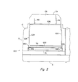
- the receiving section 126 is defined by the upwardly extending wall 100 and an inclined upper wall 128 extending upwardly inclinedly to the right in Figures 1 and 3.
- the receiving surface defined by the upper surface of the inclined upper wall 128 extends in a straight line upwardly inclinedly at an angle of about 45 degrees from one end portion (the left end portion in Figures 1 to 3) of the main body 602 to its other end portion (the right end portion in Figures 1 to 3).
- An auxiliary receiving member 134 is disposed on the upper end portion of the receiving section 126, namely on the upper end portion of the inclined upper wall 128.
- the illustrated auxiliary receiving member 134 is constructed of a plate-like member 136, and supporting projections 138 (only one of which is shown in Figures 1 and 3) provided in both ends of the plate-like member 136 are mounted on the upper end portion of the inclined upper wall 128 via pins 140 in such a manner as to be free to rotate.
- a pair of triangular supporting and guiding protrusions 148 spaced from each other in the direction perpendicular to the sheet surface in Figures 1 and 3 and in the vertical direction in Figure 2, are provided in the right surface in Figures 1 and 3 of the plate-like member 136.
- the auxiliary receiving member 134 of the above structure is free to pivot between a first position and a second position shown in Figure 1.
- a supporting surface of the pair of supporting and guiding protrusions 148 abut with the upper wall 149 of the housing 12 to hamper accurately the pivoting movement of the auxiliary receiving member 134 in the opening direction.
- the auxiliary receiving member 134 is pivoted to the second position, it abuts with the inclined upper wall 128 to hamper accurately the pivoting movement of the auxiliary receiving member 134 in the closing direction.
- the auxiliary receiving member 134 is positioned downstream of the receiving section 126 in the sheet material discharging direction and its one surface (the left surface in Figure 1) extends further from the other end of the upper surface of the inclined upper wall 128 to the right in Figure 1 upwardly inclinedly in a straight line.
- the auxiliary receiving member 134 is positioned above the other end portion of the receiving portion 126, and its other surface, particularly the guide surfaces of the supporting and guiding protrusions 148 are located above the inclined upper wall 128 and extend upwardly inclinedly in a straight line to the right in Figure 3.
- An upper cover member 150 (omitted in Figure 2) for covering the receiving section 126 is attached to the opening-closing housing 12.
- the upper cover member 150 is plate-like, and is bent slightly at its central part in the left-right direction in Figure 3.
- Protruding portions 152 are provided at both ends of the base portion of the upper cover member 150, and a stop portion 156 is provided in the free end portion of the upper cover member 150.
- the protruding portions 152 are rotatably mounted to the opening-closing housing 12 via pins 154.
- a gripping protrusion 158 is further provided at the end of the stop portion 156. With this arrangement, the upper cover member 150 can be easily pivoted in the directions and positions shown in Figure 1 by holding the gripping protrusion 158.
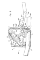
- the feed unit 604 is provided with a nearly rectangular parallelpipedal feed housing 606, and a feed means is mounted on it.
- the feed means has a cassette receiving section 608 defined within the housing 606, and a feed roller 612 to be rotated in the direction shown by an arrow 610 is disposed above the cassette receiving section 608.
- a loading opening 614 is defined in the right surface in Figure 1 of the housing 606, and a box-like cassette 616 is detachably loaded into the cassette-receiving section 608 through the opening 614.
- a carrying plate 618 adapted to be biased upwardly by the action of a biasing means (not shown) with its rear end as a fulcrum is provided in the cassette 616. Sheet materials in the stacked state are filled in the carrying plate 618.
- a delivery opening 620 is defined in the left surface of the feed housing 516 in Figure 1.
- a pair of guide plates 622 defining a delivery passage are disposed between the delivery opening 620 and the cassette-receiving section 608.
- the feed roller 612 When in this feed unit 604, the feed roller 612 is rotated in the direction of arrow 610, the uppermost sheet material in the cassette 616 is fed from the cassette 616 by the action of the feed roller 612.
- the fed sheet material passes between the pair of guide plates 622 and is conveyed to the delivery opening 620. It is delivered outside the feed housing 606 through the delivery opening 620.
- the illustrated embodiment is further constructed as shown below with regard to the hand-insertion feed means 70.
- the hand-insertion feed means 70 includes - as already mentioned above - a table 624.
- the table 624 is provided with a plate-like main body 626, and side walls 628 are provided at both side ends of the main body 626 (see Figure 2).
- the inner surfaces of the side walls 628 act as a guide surface for guiding the sheet material in the inserting direction.
- At one end portion (the downstream end portion of the sheet inserting direction, and in Figure 1, the left end portion) of each of the side walls 628 is provided integrally a supporting protrusion 630 extending to the left in Figure 1.
- the supporting projection 630 is pivotally mounted on a bracket member (not shown) secured to the inner surface of the right wall 634 of the housing 12 via supporting pins 632.
- a bracket member (not shown) secured to the inner surface of the right wall 634 of the housing 12 via supporting pins 632.
- an abutting piece 636 extending nearly perpendicularly from the main body 626 of the table 624 is provided in the base portion (the downstream end portion in the sheet inserting direction) of the main body 626, and a guide projecting piece 638 is provided integrally in the end of the abutting piece 636.
- the table 624 when a sheet material is to be fed by the hand-insertion feed means 70, the table 624 is held at a feed position shown in Figure 1.
- the abutting piece 636 abuts with the wall 80 of the lower housing 8 to hold the table 624 exactly at the feed position.
- the upper surface of the main body 626 of the table extends nearly horizontally toward the introduction opening 76 defined in the right surface of the machine housing 6. Accordingly, when a sheet material is positioned on the upper surface of the main body 626 and moved along the inner surfaces of the side walls 628, the sheet material is introduced into the machine housing 6 through the introduction opening 76.
- the sheet material so introduced passes between the upper edge of the guiding protrusion 82 provided in the wall 80 and the guide plate 78 and is fed into the conveying passage 69.
- the table 624 is held at a storage position shown in Figures 2 and 3.
- the table 624 is pivoted upwardly from the feed position at an angle of about 90 degrees in the direction shown by arrow 646, the upper edges of the side walls 628 of the table 624 abut with the wall 634 of the housing 12 to hold the table 24 in the storage position.
- the table 624 extends nearly perpendicularly in the upward direction substantially along the wall 634 of the opening-closing housing 12, and is stored outwardly of the wall 634, as shown in Figure 3.
- the introduction opening 76 is opened to outside view below the abutting piece 636 of the table 624.
- the feed unit 604 is adapted to be detachably secured to that side of the machine housing 6 at which the introduction opening 76 is formed.
- the table 624 is held at the storage position in the manner described above. Then, the feed unit 604 is moved in the direction of arrow 648 ( Figure 1) and held at the position shown in Figure 3. Thereafter, the feed unit 604 is connected to the main body 602 of the machine by a releasable lock means (not shown).
- the lock means may be a known means equipped with, for example, an engaging member, which is free to pivot between a locking position at which it engages part of the main body 602 and a non-locking position at which the above engagement is cancelled.
- the sheet material delivered from the delivery opening 620 is introduced into the machine housing 6 through the introduction opening 76 and fed to the conveying passage past the space between the upper edge of the guide protrusion 82 and the guide plate 78.
- a space is created between the abutting piece 636 and the guide projecting piece 638 and the part 650a of the upper wall 650 of the housing 606, and the left end of this space in Figure 3 is connected to the introduction opening 76.
- the delivery opening 620 is connected to the lower portion of the introduction opening 76, and the above space, to the upper portion of the introduction opening 76.
- the space so formed can be used as an insertion opening for inserting a sheet material by hand.
- the sheet material inserted through the insertion opening is guided between the part 650a of the upper wall 650 and the guide projecting piece 638 and the abutting piece 636 and fed to the conveying passage through the introduction opening 76.
- the feed unit 604 may be removed by releasing the locking obtained by the locking means (not shown) and then moving the feed unit 604 in a direction opposite to the direction of arrow 648.
- the table 624 is pivoted in the direction of arrow 646 and held at the feed position.
Landscapes
- Physics & Mathematics (AREA)
- General Physics & Mathematics (AREA)
- Engineering & Computer Science (AREA)
- General Engineering & Computer Science (AREA)
- Theoretical Computer Science (AREA)
- Collation Of Sheets And Webs (AREA)
- Separation, Sorting, Adjustment, Or Bending Of Sheets To Be Conveyed (AREA)
- Delivering By Means Of Belts And Rollers (AREA)
- Sheets, Magazines, And Separation Thereof (AREA)
- Electrophotography Configuration And Component (AREA)
Applications Claiming Priority (8)
| Application Number | Priority Date | Filing Date | Title |
|---|---|---|---|
| JP282201/87 | 1987-11-10 | ||
| JP62282201A JP2551438B2 (ja) | 1987-11-10 | 1987-11-10 | 画像形成装置 |
| JP62283078A JP2514381B2 (ja) | 1987-11-11 | 1987-11-11 | 画像形成装置 |
| JP283078/87 | 1987-11-11 | ||
| JP62300079A JPH0721661B2 (ja) | 1987-11-30 | 1987-11-30 | 画像形成装置 |
| JP62300074A JPH0725472B2 (ja) | 1987-11-30 | 1987-11-30 | 画像形成装置 |
| JP300079/87 | 1987-11-30 | ||
| JP300074/87 | 1987-11-30 |
Related Parent Applications (1)
| Application Number | Title | Priority Date | Filing Date |
|---|---|---|---|
| EP88118572.2 Division | 1988-11-08 |
Publications (2)
| Publication Number | Publication Date |
|---|---|
| EP0526916A2 true EP0526916A2 (en) | 1993-02-10 |
| EP0526916A3 EP0526916A3 (enExample) | 1995-02-08 |
Family
ID=27479267
Family Applications (4)
| Application Number | Title | Priority Date | Filing Date |
|---|---|---|---|
| EP92118353A Withdrawn EP0526916A2 (en) | 1987-11-10 | 1988-11-08 | Image-forming machine |
| EP92118355A Withdrawn EP0545067A2 (en) | 1987-11-10 | 1988-11-08 | Image-forming machine |
| EP88118572A Expired - Lifetime EP0315947B1 (en) | 1987-11-10 | 1988-11-08 | Image-forming machine |
| EP92118354A Expired - Lifetime EP0526917B1 (en) | 1987-11-10 | 1988-11-08 | Image-forming machine |
Family Applications After (3)
| Application Number | Title | Priority Date | Filing Date |
|---|---|---|---|
| EP92118355A Withdrawn EP0545067A2 (en) | 1987-11-10 | 1988-11-08 | Image-forming machine |
| EP88118572A Expired - Lifetime EP0315947B1 (en) | 1987-11-10 | 1988-11-08 | Image-forming machine |
| EP92118354A Expired - Lifetime EP0526917B1 (en) | 1987-11-10 | 1988-11-08 | Image-forming machine |
Country Status (4)
| Country | Link |
|---|---|
| US (2) | US4968016A (enExample) |
| EP (4) | EP0526916A2 (enExample) |
| KR (1) | KR930006449B1 (enExample) |
| DE (2) | DE3855368T2 (enExample) |
Cited By (2)
| Publication number | Priority date | Publication date | Assignee | Title |
|---|---|---|---|---|
| DE19706484A1 (de) * | 1996-03-07 | 1997-09-11 | Hewlett Packard Co | Blattmedienhandhabungssystem |
| EP0694820A3 (en) * | 1994-07-28 | 1998-03-18 | Sharp Kabushiki Kaisha | Sheet feeding/discharging device designed for image forming apparatus |
Families Citing this family (22)
| Publication number | Priority date | Publication date | Assignee | Title |
|---|---|---|---|---|
| EP0526916A2 (en) * | 1987-11-10 | 1993-02-10 | Mita Industrial Co. Ltd. | Image-forming machine |
| EP0418793B1 (en) * | 1989-09-18 | 1996-01-17 | Canon Kabushiki Kaisha | Recording apparatus |
| EP0446840B1 (en) * | 1990-03-12 | 1996-10-09 | Canon Kabushiki Kaisha | Automatic paper feed apparatus |
| KR930011661B1 (ko) * | 1990-10-25 | 1993-12-16 | 현대전자산업 주식회사 | 급지카세트를 제거한 레이저 빔 프린터 |
| US5101240A (en) * | 1990-10-31 | 1992-03-31 | Xerox Corporation | System for aligning a printer with a finisher |
| EP0492638B1 (en) * | 1990-12-28 | 1996-10-09 | Canon Kabushiki Kaisha | Recording system with automatic sheet supplying apparatus |
| JP2984066B2 (ja) * | 1991-01-29 | 1999-11-29 | 富士通アイソテック株式会社 | プリンタ用自動給紙装置 |
| US5988809A (en) * | 1991-09-12 | 1999-11-23 | Canon Kabushiki Kaisha | Recording apparatus with system for stacking , supplying and guiding recording media |
| US5621451A (en) * | 1993-01-18 | 1997-04-15 | Canon Kabushiki Kaisha | Image forming apparatus |
| JP3135094B2 (ja) * | 1993-03-13 | 2001-02-13 | 株式会社リコー | 統合ビジネス用ネットワークシステム |
| JPH0761614A (ja) * | 1993-08-20 | 1995-03-07 | Riso Kagaku Corp | 画像形成装置及びシートの供給ユニット |
| US5449168A (en) * | 1994-03-31 | 1995-09-12 | Eastman Kodak Company | Sorting apparatus and sorting and processing apparatus |
| US5779235A (en) * | 1995-04-27 | 1998-07-14 | Ricoh Company, Ltd. | Paper feed apparatus |
| US6267368B1 (en) * | 1998-01-19 | 2001-07-31 | Kyocera Mita Corporation | Paper return device and image forming apparatus |
| US6496281B1 (en) * | 1998-01-19 | 2002-12-17 | Kyocera Mita Corporation | Image forming apparatus |
| US6082730A (en) * | 1998-09-29 | 2000-07-04 | Lexmark International, Inc. | Integrated long sheet feeder |
| US7180638B1 (en) | 2000-02-16 | 2007-02-20 | Ricoh Co., Ltd. | Network fax machine using a web page as a user interface |
| US6484008B2 (en) * | 2000-12-19 | 2002-11-19 | Hewlett-Packard Company | Recirculating type paper drive for a direct transfer color printer |
| JP4135472B2 (ja) * | 2002-11-05 | 2008-08-20 | ブラザー工業株式会社 | 画像形成装置 |
| US20050157112A1 (en) | 2004-01-21 | 2005-07-21 | Silverbrook Research Pty Ltd | Inkjet printer cradle with shaped recess for receiving a printer cartridge |
| US7448734B2 (en) * | 2004-01-21 | 2008-11-11 | Silverbrook Research Pty Ltd | Inkjet printer cartridge with pagewidth printhead |
| US20060214353A1 (en) * | 2005-03-23 | 2006-09-28 | Lexmark International, Inc. | Integrated media input tray with manual feeder |
Family Cites Families (26)
| Publication number | Priority date | Publication date | Assignee | Title |
|---|---|---|---|---|
| US3957264A (en) * | 1975-08-07 | 1976-05-18 | International Business Machines Corporation | Collator bins |
| DE2760090C2 (de) * | 1976-06-02 | 1984-07-05 | Mita Industrial Co., Ltd., Osaka | Entwicklungsvorrichtung für ein elektrofotografisches Kopiergerät |
| GB1597910A (en) * | 1977-05-17 | 1981-09-16 | Ricoh Kk | Sheet feed apparatus |
| JPS5720758A (en) * | 1980-07-14 | 1982-02-03 | Olympus Optical Co Ltd | Collator |
| JPS57151563A (en) * | 1981-03-17 | 1982-09-18 | Toshiba Corp | Sorter |
| JPS57156960A (en) * | 1981-03-18 | 1982-09-28 | Toshiba Corp | Sorter device |
| JPS57156934A (en) * | 1981-03-20 | 1982-09-28 | Olympus Optical Co Ltd | Jam preventing delivery guide equipment of paper delivery device |
| JPS586845A (ja) * | 1981-06-30 | 1983-01-14 | Minolta Camera Co Ltd | 記録装置 |
| JPS6019657A (ja) * | 1983-07-15 | 1985-01-31 | Fuji Xerox Co Ltd | 用紙丁合い装置 |
| US4627707A (en) * | 1984-06-16 | 1986-12-09 | Ricoh Company, Ltd. | Copier with image editing function |
| JPS6186337A (ja) * | 1984-10-04 | 1986-05-01 | Ricoh Co Ltd | 複写機の紙処理装置 |
| JPH0639293B2 (ja) * | 1984-10-31 | 1994-05-25 | 富士ゼロックス株式会社 | 用紙給送装置 |
| JPS61109071A (ja) * | 1984-11-01 | 1986-05-27 | Sharp Corp | ソ−タを有する複写機 |
| JPS61124467A (ja) * | 1984-11-19 | 1986-06-12 | Canon Inc | シ−ト材搬送装置 |
| US4763165A (en) * | 1985-03-18 | 1988-08-09 | Kabushiki Kaisha Toshiba | Image forming apparatus with image adding function |
| US4799084A (en) * | 1985-04-09 | 1989-01-17 | Canon Kabushiki Kaisha | Image forming apparatus |
| JPS61238620A (ja) * | 1985-04-12 | 1986-10-23 | Hitachi Ltd | 画像記録装置 |
| JPS62121179A (ja) * | 1985-11-18 | 1987-06-02 | Canon Inc | シ−ト材分類装置 |
| JPS62210478A (ja) * | 1986-03-11 | 1987-09-16 | Mita Ind Co Ltd | 画像形成装置におけるドラムユニツトの交換時期警告方法 |
| JPS6323170A (ja) * | 1986-07-01 | 1988-01-30 | Minolta Camera Co Ltd | 複写機 |
| FR2603714A1 (fr) * | 1986-09-05 | 1988-03-11 | Ricoh Kk | Appareil electrostatique d'enregistrement pour copieur, telecopieur et imprimante |
| US4761663A (en) * | 1987-03-02 | 1988-08-02 | Eastman Kodak Company | Compact printer having convertible discharge hopper |
| JPS648134A (en) * | 1987-06-29 | 1989-01-12 | Toshiba Corp | Feeder |
| JPS6418134A (en) * | 1987-07-14 | 1989-01-20 | Seiko Epson Corp | Viewfinder lens adjusting mechanism |
| JPH0197272A (ja) * | 1987-10-09 | 1989-04-14 | Asahi Chem Ind Co Ltd | 透湿防水シート |
| EP0526916A2 (en) * | 1987-11-10 | 1993-02-10 | Mita Industrial Co. Ltd. | Image-forming machine |
-
1988
- 1988-11-08 EP EP92118353A patent/EP0526916A2/en not_active Withdrawn
- 1988-11-08 EP EP92118355A patent/EP0545067A2/en not_active Withdrawn
- 1988-11-08 DE DE3855368T patent/DE3855368T2/de not_active Expired - Fee Related
- 1988-11-08 EP EP88118572A patent/EP0315947B1/en not_active Expired - Lifetime
- 1988-11-08 DE DE3887825T patent/DE3887825T2/de not_active Expired - Fee Related
- 1988-11-08 EP EP92118354A patent/EP0526917B1/en not_active Expired - Lifetime
- 1988-11-10 KR KR1019880014797A patent/KR930006449B1/ko not_active Expired - Fee Related
- 1988-11-10 US US07/269,716 patent/US4968016A/en not_active Expired - Lifetime
-
1990
- 1990-03-22 US US07/497,258 patent/US5056768A/en not_active Expired - Lifetime
Cited By (4)
| Publication number | Priority date | Publication date | Assignee | Title |
|---|---|---|---|---|
| EP0694820A3 (en) * | 1994-07-28 | 1998-03-18 | Sharp Kabushiki Kaisha | Sheet feeding/discharging device designed for image forming apparatus |
| CN1071202C (zh) * | 1994-07-28 | 2001-09-19 | 夏普公司 | 成象装置的给排纸装置 |
| DE19706484A1 (de) * | 1996-03-07 | 1997-09-11 | Hewlett Packard Co | Blattmedienhandhabungssystem |
| DE19706484C2 (de) * | 1996-03-07 | 2000-08-17 | Hewlett Packard Co | Blatthandhabungssystem |
Also Published As
| Publication number | Publication date |
|---|---|
| EP0526916A3 (enExample) | 1995-02-08 |
| EP0545067A3 (enExample) | 1995-02-22 |
| US5056768A (en) | 1991-10-15 |
| KR890008725A (ko) | 1989-07-12 |
| US4968016A (en) | 1990-11-06 |
| EP0545067A2 (en) | 1993-06-09 |
| DE3855368D1 (de) | 1996-07-18 |
| DE3887825D1 (de) | 1994-03-24 |
| DE3855368T2 (de) | 1997-02-20 |
| EP0315947A3 (en) | 1989-12-27 |
| EP0526917B1 (en) | 1996-06-12 |
| EP0315947B1 (en) | 1994-02-16 |
| KR930006449B1 (ko) | 1993-07-16 |
| DE3887825T2 (de) | 1994-08-25 |
| EP0315947A2 (en) | 1989-05-17 |
| EP0526917A2 (en) | 1993-02-10 |
| EP0526917A3 (enExample) | 1995-02-08 |
Similar Documents
| Publication | Publication Date | Title |
|---|---|---|
| EP0526916A2 (en) | Image-forming machine | |
| JP3997817B2 (ja) | 現像装置および画像形成装置 | |
| EP0361426B1 (en) | Image-forming machine | |
| US5157416A (en) | Laser scanner protecting mechanism | |
| EP0193170A1 (en) | Shell-type electrostatic copying apparatus | |
| JPH1020595A (ja) | 電子写真画像形成装置 | |
| JPH06110262A (ja) | 画像形成装置 | |
| JPH0437988B2 (enExample) | ||
| JP2000231321A (ja) | 画像形成装置 | |
| WO1998030938A1 (fr) | Appareil de formation d'images | |
| JP2000267549A (ja) | 感光体カートリッジ及び画像形成装置 | |
| KR930012270B1 (ko) | 화상 형성장치 | |
| JPH0822705B2 (ja) | 画像生成装置 | |
| JP2632326B2 (ja) | 画像形成装置 | |
| JPH05224530A (ja) | トナー補給装置 | |
| KR930012268B1 (ko) | 화상 형성장치 | |
| JP2514381B2 (ja) | 画像形成装置 | |
| JP2934256B2 (ja) | 画像形成装置における現像装置 | |
| JP2000194241A (ja) | 画像形成機 | |
| JP2536023Y2 (ja) | 電子写真装置の排紙装置 | |
| JPS6261951B2 (enExample) | ||
| JPH07253696A (ja) | 画像形成装置 | |
| JPH0659574A (ja) | トナー補給装置 | |
| JPS6229787B2 (enExample) | ||
| JP2000037926A (ja) | 画像形成装置 |
Legal Events
| Date | Code | Title | Description |
|---|---|---|---|
| PUAI | Public reference made under article 153(3) epc to a published international application that has entered the european phase |
Free format text: ORIGINAL CODE: 0009012 |
|
| 17P | Request for examination filed |
Effective date: 19921027 |
|
| AC | Divisional application: reference to earlier application |
Ref document number: 315947 Country of ref document: EP |
|
| AK | Designated contracting states |
Kind code of ref document: A2 Designated state(s): DE FR GB NL |
|
| PUAL | Search report despatched |
Free format text: ORIGINAL CODE: 0009013 |
|
| AK | Designated contracting states |
Kind code of ref document: A3 Designated state(s): DE FR GB NL |
|
| 17Q | First examination report despatched |
Effective date: 19950831 |
|
| STAA | Information on the status of an ep patent application or granted ep patent |
Free format text: STATUS: THE APPLICATION IS DEEMED TO BE WITHDRAWN |
|
| 18D | Application deemed to be withdrawn |
Effective date: 19960111 |