EP0517286B1 - Vorrichtung zur Trocknung einer Bahn - Google Patents
Vorrichtung zur Trocknung einer Bahn Download PDFInfo
- Publication number
- EP0517286B1 EP0517286B1 EP92114245A EP92114245A EP0517286B1 EP 0517286 B1 EP0517286 B1 EP 0517286B1 EP 92114245 A EP92114245 A EP 92114245A EP 92114245 A EP92114245 A EP 92114245A EP 0517286 B1 EP0517286 B1 EP 0517286B1
- Authority
- EP
- European Patent Office
- Prior art keywords
- dryer
- web
- dryer section
- drying
- section
- Prior art date
- Legal status (The legal status is an assumption and is not a legal conclusion. Google has not performed a legal analysis and makes no representation as to the accuracy of the status listed.)
- Expired - Lifetime
Links
Images


Classifications
-
- D—TEXTILES; PAPER
- D21—PAPER-MAKING; PRODUCTION OF CELLULOSE
- D21F—PAPER-MAKING MACHINES; METHODS OF PRODUCING PAPER THEREON
- D21F5/00—Dryer section of machines for making continuous webs of paper
- D21F5/02—Drying on cylinders
- D21F5/04—Drying on cylinders on two or more drying cylinders
-
- D—TEXTILES; PAPER
- D21—PAPER-MAKING; PRODUCTION OF CELLULOSE
- D21F—PAPER-MAKING MACHINES; METHODS OF PRODUCING PAPER THEREON
- D21F5/00—Dryer section of machines for making continuous webs of paper
- D21F5/02—Drying on cylinders
- D21F5/04—Drying on cylinders on two or more drying cylinders
- D21F5/042—Drying on cylinders on two or more drying cylinders in combination with suction or blowing devices
-
- D—TEXTILES; PAPER
- D21—PAPER-MAKING; PRODUCTION OF CELLULOSE
- D21G—CALENDERS; ACCESSORIES FOR PAPER-MAKING MACHINES
- D21G9/00—Other accessories for paper-making machines
- D21G9/0063—Devices for threading a web tail through a paper-making machine
Definitions
- This invention relates to a dryer apparatus for drying both sides of a web of paper emerging from a press section of a paper making machine, the dryer apparatus being of the kind defined in the preamble of claim 1.
- Bel Run is a registered trademark of Beloit Corporation.
- the bottom ineffective dryers are replaced by vacuum rolls which positively convey the web from one cylinder to the next.
- Recent installations of this type of dryer section have shown that the Bel Run concept can be extended to include a large number of dryers without any adverse effect on the web runability. The web runability is not affected because the vacuum rolls are capable of conveying the web along the felt supported spans without the need for sheet tension or section draw points.
- a dryer apparatus of the kind defined in the preamble of claim 1 is disclosed in Fig. 10 and the corresponding description on page 628 of an article by J. Linderot: "10rance mit Ge onceer Bahn entry in derurpartie", published in "Wochenblatt für Textilfabrikation", No. 16 of 1986, pages 623-628.
- the known dryer apparatus includes a first dryer section ("erstejane, Bel-Run") which is a single-tier dryer section having a plurality of drying cylinders arranged in a horizontally extending single-tier, and a plurality of vacuum rolls each of which is disposed in spaced close proximity to and between adjacent drying cylinders.
- the vacuum rolls are lesser in diameter than the drying cylinders of the first dryer section and are disposed below the drying cylinders of the first dryer section.
- a second dryer section is disposed horizontally adjacent to and downstream of the first dryer section.
- the second dryer section constituting the fourth group of drying cylinders is of the type having two rows of drying cylinders arranged one above the other, and a single felt extending alternately around a top drying cylinder and a bottom drying cylinder, with the felt being sandwiched between the web and the surface of the bottom drying cylinders.
- the web is sandwiched between the felt and the surface of the top drying cylinders.
- the known dryer apparatus further includes a third and a fourth dryer section constituting a fifth and a sixth group of drying cylinders respectively.
- the third and fourth dryer sections each are of the type having top and bottom drying cylinders and top and bottom felts. In such a dryer section type the web is transferred respectively from each top cylinder to a respective one of the bottom cylinders and from each bottom cylinder to a respective one of the top cylinders in an open draw.
- the web is transferred without open draw from the last dryer of the first dryer section to the first dryer of the second dryer section by means of the single felt associated with the second dryer section.
- the single felt associated with the second dryer section supports the web at one side as it travels from the last drying cylinder of the first dryer section to the first drying cylinder of the second dryer section.
- the first dryer section of the known apparatus is a single-tier dryer section
- the web is dried from only one side as it is passed through the first dryer section.
- the second, third and fourth dryer sections the web is dried from both sides as it passes alternately around sequential top and bottom cylinders.
- the heat transfer from the bottom cylinders of the second dryer section to the web is less efficient than the heat transfer from the top cylinders of the second dryer section to the web because the felt is interposed between the web and the bottom cylinders whereas the top cylinders of the second dryer section are in direct contact with the web.
- the web normally shrinks both in the machine direction and in the cross machine direction as it travels from the last drying cylinder of the first dryer section to the first drying cylinder of the second dryer section and around the bottom cylinders of the second dryer section of the known apparatus.
- the dried paper tends to curl if it is allowed to shrink during drying and also if the two sides of the web are dried unevenly.
- uneven drying of both sides of the web can be avoided by suitably adjusting the steam pressures of the top and bottom drying cylinders separately.
- the web is permitted to shrink in the known apparatus whenever it is not held between the felt and the surface of a drying cylinder.
- FR-A-2 386 638 discloses a dryer apparatus comprising first and second dryer sections each having two rows of heated drying cylinders disposed one above the other and a single felt wrapped around the top and bottom cylinders in a serpentine configuration.
- the web is transferred with open draw from the first dryer section to the second dryer section.
- the arrangement is such that that side of the web which is in direct heat transfer contact with the drying cylinders is reversed as the web is transferred from the first dryer section to the second dryer section.
- the bottom drying cylinders of the first dryer section and the top drying cylinders of the second dryer section are grooved.
- the grooves defined in the surface of these drying cylinders are evacuated by means of external vacuum boxes disposed in the pockets between adjacent drying cylinders.
- the felt supported draws between top and bottom cylinders of each section are large, thereby permitting the web to shrink as it is moved through these felt supported draws. Shrinkage of the web during drying, however, is one cause of curl of the dried paper as stated above.
- An object of the invention is to modify the dryer apparatus of the kind defined in the preamble of claim 1 so that the web can be readily inspected during its transfer from the single-tier dryer section to the further dryer section. Moreover, the removal of broke is to be facilitated. Furthermore, the tendency of the dried paper to curl is to be minimized.
- Another object of the present invention is the provision of an apparatus for drying a web of paper in which blow boxes would be redundant.
- Another object of the present invention is the provision of an apparatus for drying a web of paper in which ventilation of the pockets defined by the cylinders and the vacuum rolls is improved, thereby improving the drying rate of the web.
- Another object of the present invention is the provision of an apparatus for drying a web of paper in which gear case leaks are inhibited and removal of broke is facilitated.
- Another object of the present invention is the provision of an apparatus for drying a web of paper in which fewer steamfits are required and none of the dryers is redundant, thereby reducing the blow through rate.
- Another object of the present invention is the provision of an apparatus for drying a web of paper in which the frame is symmetrical and in which the base frame is subjected to equal loading forces, thereby resulting in a sturdy low-profile frame which reduces vibration and its attendant noise level.
- Another object of the present invention is the provision of an apparatus for drying a web of paper in which the power required to drive the cylinders is reduced and due to the layout and configuration of the dryers, such arrangement lends itself to the provision of a low-profile hood.
- Another object of the present invention is the provision of an apparatus for drying a web of paper in which runability of the drying apparatus is increased and in which doctors can be applied to each dryer.
- Another object of the present invention is the provision of an apparatus for drying a web in which open access to the dryers and vacuum rolls is provided and a supply of air can be fed uniformly through each of the vacuum rolls.
- Another object of the present invention is the provision of an apparatus for drying a web of paper in which hoods are provided over and adjacent the vacuum rolls for handling the humid exhaust and possibly eliminating the need for large scale exhaust hood construction.
- Another object of the present invention is the provision of an apparatus for drying a web of paper in which such vacuum roll hoods can be provided for profiling the web by removing exhaust air from selected transfer sections of these hoods.
- Another object of the present invention is the provision of an apparatus for drying a web ranging from tissue to fine paper.
- Another object of the present invention is the provision of an apparatus for drying a web of paper in which the felt wrap is increased relative to the felt wrap of a two felt type drying section, particularly by decreasing the space between adjacent dryers.
- Another object of the present invention is the provision of an apparatus for drying a web of paper in which the humidity is decreased by eliminating the closed pockets associated with a typical two felt type drying section.
- Another object of the present invention is the provision of an apparatus for drying a web of paper in which the apparatus is no longer than a conventional dryer section but requires less equipment.
- Another object of the present invention is the provision of an apparatus for drying a web of paper in which the felt supported draw is reduced to a minimum.
- Another object of the present invention is the provision of an apparatus for drying a web of paper in which sheet control is provided by the direct application of vacuum.
- Another object of the present invention is the provision of an apparatus for drying a web of paper in which there is no need for residual sheet tension to hold the sheet against the felt since the sheet is entirely supported by vacuum as it wraps the transfer roll.
- Another object of the present invention which is a less obvious factor relative to the runability of the dryer section is the uniformity of dryer surface speeds.
- Such uniformity is obtained because the dryers are driven by the felt instead of by a gear train. Dryers which are geared together are forced to run at equal rotational speeds. In the case of dryers which have slightly different diameters, perhaps due to manufacturing tolerances or differences in steam pressure, such differences result in unequal dryer surface speeds. These unequal surface speeds not only increase the drive load but also cause problems with sheet runability.
- each of the dryers can be easily fitted with a doctor, such doctors being unloaded automatically with air cylinders if required.
- the apparatus according to the present invention permits a significant reduction in the amount of paper machinery which is required to meet the design production.
- the present invention enables simplification of the dryer framing.
- Another object of the present invention is the provision of an apparatus for drying a web of paper in which the energy efficiency of the apparatus is improved.
- the dryer section of the present invention provides improved energy efficiency in the following three areas.
- Another object of the present invention is the provision of an apparatus for drying a web of paper in which the quality of the sheet is improved.
- the dryer section according to the present invention has the capability of influencing the sheet properties as follows. First, the tensile strength and stretch of the web in the machine direction is improved. Second, the tensile strength and stretch of the web in the cross machine direction is improved. Third, the tendency for the sheet to curl is reduced and fourth, the tendency to generate edge cockles is reduced.
- the machine direction tensile and stretch are influenced primarily by the press section draw and somewhat less by the draw between dryer sections.
- these dryer draws are usually set as low as possible but the minimum draw is dictated by runability and sheet control.
- the machine direction properties can still be influenced in the usual way by pulling a draw between sections if such is deemed desirable.
- the cross machine direction tensile and stretch are influenced by the cross machine direction sheet restraint.
- the sheet In an open draw, there is no restraint, so the sheet freely shrinks (although this shrinkage is greatest at the edges).
- Uno-Run type drying section In operation of a Uno-Run type drying section, there is a degree of web restraint as evidenced by the increase in trim and the decrease in edge cockles.
- the sheet restraint is more positive than that provided by a Uno-Run system and this further reduces any tendency for edge cockles to develop.
- a slight increase in cross machine direction tensile and a decrease in cross machine direction stretch is evident.
- the decrease in cross machine direction stretch is most pronounced at the edges where the sheet normally has the least restraint. Accordingly, the net effect according to the present invention, will be a sheet with more uniform properties in the cross machine direction.
- the propensity to curl is caused by three factors as follows. First, fiber orientation, second fines and filler (bonding) distribution, and third, residual fiber stress.
- the dryer section influences only the fiber stress. Curl is normally controlled by adjusting the drying from each side of the sheet by separate control of the top and bottom dryer steam pressures.
- Another particularly important object of the present invention is the provision of an apparatus for drying fine paper grades where directionality is important. More particularly, restrained drying of the web is an important feature of the present invention in that it will not permit the edges of the sheet to shrink more than the center portion of the sheet.
- the key to restraining the sheet while it is not held between the felt and the dryer drum is the vacuum in the transfer, or turning roll, below adjacent drums.
- the sheet is restrained by the application of a vacuum within the range of 1.49 to 2.49 kPa (6-10 inches wc).
- the present invention relates to a single tier drying section for drying a web.
- the drying section includes a dryer and a felt guided about the dryer such that the web is disposed between the dryer and the felt for drying a first side of the web.
- a further dryer is disposed downstream relative to the dryer and a further felt is guided about the further dryer such that the web is disposed between the further dryer and the further felt for drying a second side of the web.
- a dryer transfer means transfers the web from the dryer to the further dryer.
- the single tier drying section extends from a press section to a calender section and includes a multiplicity of single tier subsections.
- the arrangement is such that alternate sides of the web are sequentially dried as the web progresses through the subsections and each of the subsections is disposed at a different height relative to each other with preferably every other subsection disposed at the same height relative to each other.
- the dryer transfer means includes means for transferring the web with open draw from the dryer to the further dryer.
- the present invention relates to an apparatus for drying a web of paper emerging from the press section of a papermaking machine.
- the apparatus includes a first dryer section means for initiating the drying of the first side of the web.
- the first transfer means transfers the web from the press section to the first dryer section means.
- a second dryer section means is disposed downstream relative to the first dryer section means for initiating the drying of the second side of the web.
- the second side of the web is opposite to the first side of the web.
- a first dryer transfer means transfers the web between the first and the second dryer section means such that the drying of both sides of the web is permitted.
- the first dryer section means also includes a first dryer section for initiating the drying of the first side of the web and a second section disposed downstream relative to the first dryer section for continuing the drying of the first side of the web.
- a second dryer transfer means transfers the web without open draw between the first and the second dryer sections.
- the first dryer section includes a first plurality of dryers and a first plurality of vacuum rolls with each of the vacuum rolls being disposed adjacent to a corresponding dryer of the first plurality of dryers such that the web extends alternately past each vacuum roll and a dryer in serpentine configuration.
- the first felt extends around the first plurality of dryers and the first plurality of vacuum rolls in close conformity with the web.
- the second dryer section includes a second plurality of dryers and a second plurality of vacuum rolls with each vacuum roll of the second plurality of vacuum rolls being disposed adjacent to a corresponding dryer of the second plurality of dryers, such that the web extends alternately past each vacuum roll and dryer in serpentine configuration.
- a second felt extends around the second plurality of dryers and vacuum rolls respectively such that the second felt is disposed in close conformity with the web.
- the second felt and an unfelted portion of a downstream dryer of the first dryer section defines a first pick-up section for transferring the web from the unfelted portion onto the second felt so that the web is transferred without open draw from the first dryer section to the second dryer section.
- Each of the vacuum rolls of the first and the second dryer sections is disposed in spaced close proximity to its adjacent corresponding dryer such that the felt draw between each of the vacuum rolls and the corresponding dryer is minimal, thereby inhibiting any tendency of the web to flutter relative to the supporting felts.
- the apparatus also includes a base frame for rotatably supporting the first and the second plurality of dryers such that the axes of the first and the second plurality of dryers are disposed in a first plane.
- the frame also rotatably supports the first and the second plurality of vacuum rolls such that the axes of the first and second plurality of vacuum rolls are disposed in a second plane with the first plane being disposed above the second plane.
- An upstream vacuum roll of the second plurality of vacuum rolls is disposed in close proximity to the unfelted portion of the downstream dryer of the first dryer section.
- a first felt roll is rotatably supported by the base frame for guiding the second felt past and in conformity with the unfelted portion of the downstream dryer and thereafter around the upstream vacuum roll of the second dryer section such that the web is transferred from the unfelted portion to the second felt without open draw.
- the first transfer means for transferring the web from the press section to the first dryer section means also includes a lead in roll which is disposed in spaced close proximity relative to the press section.
- the first felt extends around the lead in roll for transferring the web from the press section to the first dryer section means.
- a guide roll is disposed between the lead in roll and the first dryer section means for assisting the transfer of the web from the press section towards the first dryer section means.
- a transfer felt extends around the guide roll such that the transfer felt and the first felt define therebetween a transfer section for transferring the web from the press section towards the first dryer section means.
- the first transfer means also includes an upstream vacuum roll of the first dryer section means. This upstream vacuum roll cooperates with the first felt and the transfer felt such that the transfer section extends from the guide roll to the upstream vacuum roll so that the web emerging from the transfer section is guided around the upstream vacuum roll into the first dryer section means.
- the second dryer section means also includes a third plurality of dryers with each of the dryers of this third plurality of dryers being disposed downstream relative to the first dryer section means.
- a third plurality of vacuum rolls are each disposed in spaced close proximity relative to a corresponding dryer of the third plurality of dryers such that the web extends alternately past each vacuum roll and dryer of the second dryer section means in serpentine configuration.
- the third plurality of dryers and vacuum rolls are rotatably secured to the base frame such that the third plurality of dryers are disposed in a third plane and the third plurality of vacuum rolls are disposed in a fourth plane with the fourth plane being disposed above the third plane.
- a third felt extends past the third plurality of dryers and vacuum rolls such that the third felt supports the web through the second dryer section means with the second side of the web being urged by the third felt into close conformity with each dryer of the third plurality of dryers.
- Subsequent dryer section means are provided such that the third, fourth and fifth dryer transfer means each permits the transfer of the web between adjacent dryer section means with an alternate reversing of the web such that the first and second side of the web are alternately dried as the web extends through the apparatus and past consecutive dryer section means.
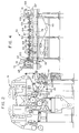
- Figure 1 is a side elevational view showing the apparatus generally designated 10 for drying a web 12 of paper emerging from a press section, generally designated 14 of a paper making machine.
- the apparatus 10 includes a first dryer section means, generally designated 16 for initiating the drying of a first side 18 of the web 12.
- a first transfer means generally designated 20 transfers the web 12 from the press section 14 to the first dryer section means 16.
- a second dryer section means generally designated 22 is disposed downstream relative to the first dryer section means 16. This second dryer section means 22 initiates the drying of a second side 24 of the web 12. The second side 24 of the web 12 being opposite to the first side 18 thereof.
- a first dryer transfer means generally designated 25 transfers the web 12 without open draw between the first and second dryer section means 16 and 22 respectively.
- the first dryer transfer means 25 transfers the web 12 without open draw between the first and second dryer section means 16 and 22, whereas the dryer transfer means 116A shown in Fig. 9 transfers the web with open draw between the first and second dryer section means 16 and 22 in accordance with the invention.
- FIG. 2 shows in more detail the first transfer means 20 and will be described in more detail hereinafter.
- FIG. 3 shows in detail the first dryer section means 16.
- This first dryer section means 16 includes a first dryer section generally designated 26 for initiating the drying of the first side 18 of the web 12.
- a second dryer section generally designated 28 is disposed downstream realtive to the first dryer section 26 for continuing the drying of the first side 18 of the web 12.
- a second dryer transfer means generally designated 30 transfers the web 12 without open draw between the first and the second dryer sections 26 and 28 respectively.
- the first dryer section also includes a first plurality of dryers 32, 34, 36, 38, 40 and 42 respectively.
- the first dryer section 26 also includes a first plurality of vacuum rolls 46, 48, 50, 52 and 54 respectively.
- Each of the first plurality of vacuum rolls 46 to 54 is disposed adjacent to a corresponding dryer of the first plurality of dryers 32 to 42 such that the web 12 extends alternately past each vacuum roll 46 to 54 and dryer 32 to 42 in serpentine configuration.
- a first felt 56 extends around the first plurality of dryers 32 to 42 and the first plurality of vacuum rolls 46 to 54 in close conformity with the web 12.
- the second dryer section 28 also includes a second plurality of dryers 58, 59, 60, 61, 62 and 63.
- the second dryer section 28 also includes a second plurality of vacuum rolls 64, 65, 66, 67, 68 and 69.
- Each of the vacuum rolls 64 to 69 is disposed adjacent to a corresponding dryer of the second plurality of dryers 58 to 63 such that the web 12 extends alternately past each vacuum roll 64 to 69 and dryer 58 to 63 in serpentine configuration.
- a second felt 72 extends around the second plurality of dryers 58 to 63 and the vacuum rolls 64 to 69 respectively such that the second felt 72 is disposed in close conformity with the web 12.
- the second felt 72 and an unfelted portion 74 of the downstream dryer 42 of said first dryers 32 to 42 defines a first pick-up section generally designated 76 for transferring the web 12 from the unfelted portion 74 onto the second felt 72 so that the web 12 is transferred without draw from the first dryer section 26 to the second dryer section 28.
- Each of the vacuum rolls of the first and the second dryer sections 26 and 28 is disposed in spaced close proximity to its adjacent corresponding dryer such that the felt draw between each of the vacuum rolls and its corresponding dryer is minimal, thereby inhibiting any tendency of the web to flutter relative to the supporting felts 56 and 72 respectively.
- the apparatus 10 also includes a base frame 78 for rotatably supporting both the first and the second plurality of dryers such that the axes of the first and second plurality of dryers are disposed in a first plane 80 as shown in Figure 3.
- the frame 78 rotatably supports the first and second plurality of vacuum rolls such that the axes of the first and the second plurality of vacuum rolls are disposed in a second plane 82 shown in Figure 3.
- the first plane 80 is disposed above the second plane 82 as shown in Figure 3.
- the apparatus 10 includes an upstream vacuum roll 64 of the second plurality of vacuum rolls and this vacuum roll 64 is disposed in spaced close proximity to the unfelted portion 74 of the downstream dryer 42 of the first dryer section 26.
- a first felt roll 84 is rotatably supported by the base frame 78 for guiding the second felt 72 past and in conformity with the unfelted portion 74 of the downstream dryer 42 and thereafter around the upstream vacuum roll 64 of the second dryer section 28 such that the web 12 is transferred from the unfelted portion 74 to the second felt 72 without open draw.
- the apparatus 10 includes a first transfer means 20 for transferring the web 12 from the press section 14 to the first dryer section means 16.
- This first transfer means 20 further includes a lead in roll 86 which is disposed in spaced close proximity relative to the press section 14.
- the first felt 56 extends around this lead in roll 86 for transferring the web 12 from the press section 14 to the first dryer section means 16.
- a guide roll 88 is disposed between the lead in roll 86 and the first dryer section means 16 for assisting the transfer of the web 12 from the press section 14 towards the first dryer section means 16.
- a transfer felt 90 extends around the guide roll 88 such that the transfer felt 90 and the first felt 56 define therebetween a transfer section 92 for transferring the web 12 from the press section 14 toward the first dryer section means 16.
- the first transfer means 20 further includes an upstream vacuum roll 44 of said first dryer section means 16.
- the upstream vacuum roll 44 cooperates with the first felt 56 and the transfer felt 90 such that the transfer section 92 extends from the guide roll 88 to the upstream vacuum roll 44 so that the web 12 emerging from the transfer section 92 is guided around the upstream vacuum roll 44 into the first dryer section means 16.
- the second dryer section means 22 also includes a third plurality of dryers 94, 95, 96, 97, 98 and 99.
- the third plurality of dryers is disposed downstream relative to the first dryer section means 16.
- a third plurality of vacuum rolls 101, 102, 103, 104 and 105 each are disposed in spaced close proximity relative to a corresponding dryer of the third plurality of dryers such that the web 12 extends alternately past each vacuum roll and dryer of the second dryer section means 22 in serpentine configuration.
- the base frame 78 rotatably supports each of the dryers of the third plurality of dryers such that the axes of the dryers are disposed in the third plane 107.
- the base frame 78 also rotatably supports each of the vacuum rolls of the third plurality of vacuum rolls 101 to 105 such that the axis of each of the vacuum rolls of the third plurality of vacuum rolls 101 to 105 is disposed in a fourth plane 108 with the fourth plane 108 being disposed above the third plane 107.
- a third felt 110 extends past the third plurality of dryers 94 to 99 and vacuum rolls 101 to 105 such that the third felt 110 supports the web 12 through the second dryer section means 22 with the second side 24 of the web 12 being urged by the third felt 110 into close conformity with each dryer of the third plurality of dryers 94 to 99.
- the first dryer transfer means includes a downstream vacuum roll 70 of the first dryer section means 16 and a downstream felt roll 112 of the first dryer section 16.
- the second felt 72 of the first dryer section means 16 extends between the downstream vacuum roll 70 and the downstream felt roll 112.
- the second felt 72 supports the web 12 such that the web is conveyed and disposed between the second felt 72 and the second dryer section means 22.
- the first dryer transfer means also includes an upstream vacuum roll 100 and and upstream felt roll 114.
- the third felt 110 extends between the upstream felt roll 114 and the upstream vacuum roll 100 of the second dryer section means 22 such that the third felt 110 and the second felt 72 define therebetween a first dryer transfer means section 116 for transferring the web without open draw from the second to the third felts 72 and 110 respectively.
- the third felt 110 presses against the web such that the second side 24 of the web is pressed into close conformity with each dryer of the third plurality of dryers 94 to 99 such that the second side 24 of the web 12 is dried.
- Figures 5, 6, and 7 respectively show third, fourth, and fifth dryer section means 118, 120 and 122 and third, fourth and fifth dryer transfer means 124, 126 and 128 for transferring and reversing the web as the web progresses through the drying apparatus.
- the third, fourth and fifth dryer transfer means 124, 126 and 128 permit the transfer of the web between the respective dryer section means 22, 118, 120 and 122 without open draw and with an alternate reversing of the web such that the first and second sides of the web are alternately dried as the web extends through the apparatus and past consecutive dryer section means 22, 118, 120 and 122.
- FIG 8 shows the details of two of the vacuum rolls 46, 48 in which pressure seals 130 may be moved from the position shown with reference to the vacuum roll 46 to that shown relative to vacuum roll 48 for counteracting the tendency of the web 12 to part from the felt 56.
- the single tier drying section 16 extends from the press section 14 to a calender section 130 or to a size press (not shown) or throughout the entire dryer section.
- the single tier drying section 16 includes a multiplicity of single tier subsections 16,22,118,120 and 122 and a plurality of dryer transfer means 25,124,126 and 128 each dryer transfer means 25,124,126 and 128 being disposed between adjacent subsections such that as the web progresses through consecutive subsections 16,22,118,120 and 122 alternate sides 18 and 24 of the web 12 are sequentially dried.
- subsections 16,22,118,120 and 122 are disposed at different heights relative to each other and preferably every other subsection 16,118 and 122 and every other subsection 22 and 120, respectively are disposed at the same height relative to each other.
- the transfer means 116A includes means 100A and 70A for transferring the web with open draw from the dryer 63A to a further dryer 94A.
- the web is transferred from the press section 14 to the first dryer section means 16. Drying of the first side 18 of the web 12 is initiated during passage of the web through the first dryer section means 16.
- the web 12 is transferred between the first dryer section means 16 and the downstream second dryer section means 22 with the web transfer being such that the web 12 is reversed so that drying of the second side 24 of the web 12 is initiated during passage of the web 12 through the second dryer section means 22.
- the web 12 is transferred between the first and second dryer section means 16 and 22 with open draw.
- the web is also transferred between subsequent dryer section means such that the first and second sides 18 and 24 of the web 12 are alternately exposed to the drying effect of the subsequent dryer section means in sequence.
Landscapes
- Drying Of Solid Materials (AREA)
- Paper (AREA)
- Color Printing (AREA)
- Lubrication Of Internal Combustion Engines (AREA)
- Coupling Device And Connection With Printed Circuit (AREA)
- Treatment Of Fiber Materials (AREA)
Claims (4)
- Trocknungsvorrichtung zum Trocknen beider Seiten (18, 24) einer Papierbahn (12), die aus einer Pressenpartie (14) einer Papiermaschine austritt, wobei die Vorrichtung folgendes umfaßt:dadurch gekennzeichnet, daßeine einreihige Trockengruppe (16) mit:einer Einzelreihe von dampfbeheizten Trocknungszylindern (32-42); 58-63) zum Trocknen einer Seite (18) der Bahn (12), wobei die eine Seite (18) in direkten Oberflächenkontakt mit jedem Trocknungszylinder (32-42; 58-63) der einreihigen Trockengruppe (16) kommt;einer Vielzahl an Saugwalzen (46-54; 64-69), wobei jede Saugwalze der Vielzahl an Saugwalzen (46-54; 64-69) im Durchmesser geringer als, und in nächster Nähe zu, und zwischen benachbarten Trocknungszylindern der Einzelreihe von Trocknungszylindern (32-42; 58-63) angeordnet ist, wobei die Vielzahl an Saugwalzen (46-54; 64-69) an einen Unterdruckerzeuger angeschlossen ist;einem Trockenfilz (56; 72), der sich abwechselnd um die Einzelreihe von Trocknungszylindern (32-42; 58-63) und der Vielzahl an Saugwalzen (46-54; 64-69) in enger Anlage an der Bahn (12) erstreckt;eine weitere Trockengruppe (22), die im wesentlichen horizontal benachbart zu und stromabwärts der einreihigen Trockengruppe (16) angeordnet ist und folgendes einschließt:eine Vielzahl an dampfbeheizten Trocknungszylindern (94-99), um mit dem Trocknen der entgegengesetzten Seite (24) der Bahn (12) zu beginnen; undeinen weiteren Trockenfilz (110), der sich um die Vielzahl an Trocknungszylindern (94-99) in enger Anlage an der Bahn (12) erstreckt; undeine Trocknerüberführungseinrichtung (116A) zum Überführen der Bahn (12) von der einreihigen Trockengruppe (16) zu der weiteren Trockengruppe (22),alle Trocknungszylinder (94-99) der weiteren Trockengruppe (22) in einer Einzelreihe angeordnet sind;die weitere Trockengruppe (22) eine weitere Vielzahl an Saugwalzen (101-105) aufweist, die an einen Unterdruckerzeuger angeschlossen sind, wobei jede Saugwalze (101-105) der weiteren Vielzahl an Saugwalzen (101-105) im Durchmesser geringer als, und in nächster Nähe zu, und zwischen benachbarten Trocknungszylindern (94-99) der weiteren Trockengruppe (22) angeordnet ist;der weitere Trockenfilz (110) sich abwechselnd um einen Trocknungszylinder (94-99) und einer benachbarten Saugwalze (101-105) der weiteren Trockengruppe (22) derart erstreckt, daß die entgegengesetzte Seite (24) der Bahn (12) in direkten Oberflächenkontakt mit jedem Trocknungszylinder (94-99) der weiteren Trockengruppe (22) kommt;die Trocknerüberführungseinrichtung (116A) eine Einrichtung (100A, 70A) zum Überführen der Bahn (12) mit einem offenen Zug vom letzten Trocknungszylinder (63) der einreihigen Trockengruppe (22) aufweist;ein Unterdruck im Bereich von 1,49 bis 2,49 kP (6-10 Zoll WS) in den Saugwalzen (46-54; 64-99; 101-105) der einreihigen Trockengruppe (16) und der weiteren Trockengruppe (22) angelegt wird, um die Bahn (12) am Schrumpfen in Maschinenrichtung und quer zur Maschinenrichtung während des Laufs der Bahn (12) durch die Trockengruppen (16; 22) zu hindern; und die Dampfdrücke, die den Trocknungszylindern der einreihigen Trockengruppe (16) und der weiteren Trockengruppe (22) zugeführt werden, für jede Trockengruppe (16; 22) getrennt einstellbar sind, um eine zusätzliche Rollneigungssteuerung der Bahn (12) zu gestatten.
- Trocknungsvorrichtung nach Anspruch 1, bei der jede Saugwalze der Vielzahl an Saugwalzen (46-54; 64-69) unter benachbarten Trocknungszylindern der Einzelreihe von Trocknungszylindern (32-42; 58-63) angeordnet ist; und jede Saugwalze der weiteren Anzahl von Saugwalzen (101-105) über benachbarten Trocknungszylindern (94-99) der weiteren Trockengruppe (22) angeordnet ist.
- Trocknungsvorrichtung nach einem der vorhergehenden Ansprüche, bei der der offene Zug zwischen einem ersten und einem zweiten Spalt gebildet ist, wobei der erste Spalt ein divergierender Spalt ist, der zwischen der Oberfläche des letzten Trocknungszylinders (63) der Einzelreihe von Trocknungszylindern (32-42; 58-63) und dem Trockenfilz (72) gebildet ist, wobei der zweite Spalt ein konvergierender Spalt ist, der zwischen der Oberfläche des ersten Trocknungszylinders (94) der weiteren Trockengruppe (22) und dem weiteren Trockenfilz (110) gebildet ist, wobei der divergierende Spalt gegenüber dem konvergierenden Spalt angeordnet ist.
- Trocknungsvorrichtung nach Anspruch 3, bei der der divergierende Spalt über dem konvergierenden Spalt angeordnet ist.
Priority Applications (3)
| Application Number | Priority Date | Filing Date | Title |
|---|---|---|---|
| EP96108351A EP0735183B1 (de) | 1987-02-13 | 1988-02-11 | Vorrichtung zur Trocknung einer Bahn |
| EP96108669A EP0733737B1 (de) | 1987-02-13 | 1988-02-11 | Vorrichtung zur Trocknung einer Bahn |
| EP96103091A EP0718435A3 (de) | 1987-02-13 | 1988-02-11 | Vorrichtung zum Trocknen einer Bahn |
Applications Claiming Priority (3)
| Application Number | Priority Date | Filing Date | Title |
|---|---|---|---|
| US07/014,569 US4934067A (en) | 1987-02-13 | 1987-02-13 | Apparatus for drying a web |
| US14569 | 1987-02-13 | ||
| EP88902314A EP0345291B1 (de) | 1987-02-13 | 1988-02-11 | Vorrichtung zur trocknung einer bahn |
Related Parent Applications (2)
| Application Number | Title | Priority Date | Filing Date |
|---|---|---|---|
| EP88902314A Division EP0345291B1 (de) | 1987-02-13 | 1988-02-11 | Vorrichtung zur trocknung einer bahn |
| EP88902314.9 Division | 1988-02-11 |
Related Child Applications (4)
| Application Number | Title | Priority Date | Filing Date |
|---|---|---|---|
| EP96108351A Division EP0735183B1 (de) | 1987-02-13 | 1988-02-11 | Vorrichtung zur Trocknung einer Bahn |
| EP96103091A Division EP0718435A3 (de) | 1987-02-13 | 1988-02-11 | Vorrichtung zum Trocknen einer Bahn |
| EP96103091.3 Division-Into | 1988-02-11 | ||
| EP96108669A Division EP0733737B1 (de) | 1987-02-13 | 1988-02-11 | Vorrichtung zur Trocknung einer Bahn |
Publications (3)
| Publication Number | Publication Date |
|---|---|
| EP0517286A2 EP0517286A2 (de) | 1992-12-09 |
| EP0517286A3 EP0517286A3 (en) | 1993-02-24 |
| EP0517286B1 true EP0517286B1 (de) | 1998-06-10 |
Family
ID=21766269
Family Applications (7)
| Application Number | Title | Priority Date | Filing Date |
|---|---|---|---|
| EP92106048A Expired - Lifetime EP0503681B1 (de) | 1987-02-13 | 1987-12-18 | Vorrichtung zum Trocknen einer Bahn |
| EP88900925A Expired - Lifetime EP0345266B2 (de) | 1987-02-13 | 1987-12-18 | Vorrichtung zur trocknung einer bahn |
| EP96108669A Expired - Lifetime EP0733737B1 (de) | 1987-02-13 | 1988-02-11 | Vorrichtung zur Trocknung einer Bahn |
| EP96103091A Withdrawn EP0718435A3 (de) | 1987-02-13 | 1988-02-11 | Vorrichtung zum Trocknen einer Bahn |
| EP96108351A Expired - Lifetime EP0735183B1 (de) | 1987-02-13 | 1988-02-11 | Vorrichtung zur Trocknung einer Bahn |
| EP92114245A Expired - Lifetime EP0517286B1 (de) | 1987-02-13 | 1988-02-11 | Vorrichtung zur Trocknung einer Bahn |
| EP88902314A Revoked EP0345291B1 (de) | 1987-02-13 | 1988-02-11 | Vorrichtung zur trocknung einer bahn |
Family Applications Before (5)
| Application Number | Title | Priority Date | Filing Date |
|---|---|---|---|
| EP92106048A Expired - Lifetime EP0503681B1 (de) | 1987-02-13 | 1987-12-18 | Vorrichtung zum Trocknen einer Bahn |
| EP88900925A Expired - Lifetime EP0345266B2 (de) | 1987-02-13 | 1987-12-18 | Vorrichtung zur trocknung einer bahn |
| EP96108669A Expired - Lifetime EP0733737B1 (de) | 1987-02-13 | 1988-02-11 | Vorrichtung zur Trocknung einer Bahn |
| EP96103091A Withdrawn EP0718435A3 (de) | 1987-02-13 | 1988-02-11 | Vorrichtung zum Trocknen einer Bahn |
| EP96108351A Expired - Lifetime EP0735183B1 (de) | 1987-02-13 | 1988-02-11 | Vorrichtung zur Trocknung einer Bahn |
Family Applications After (1)
| Application Number | Title | Priority Date | Filing Date |
|---|---|---|---|
| EP88902314A Revoked EP0345291B1 (de) | 1987-02-13 | 1988-02-11 | Vorrichtung zur trocknung einer bahn |
Country Status (9)
| Country | Link |
|---|---|
| US (1) | US4934067A (de) |
| EP (7) | EP0503681B1 (de) |
| JP (3) | JPH01503314A (de) |
| KR (3) | KR960012520B1 (de) |
| AT (6) | ATE85374T1 (de) |
| BR (2) | BR8707969A (de) |
| DE (14) | DE345266T1 (de) |
| FI (4) | FI95730C (de) |
| WO (2) | WO1988006204A1 (de) |
Families Citing this family (53)
| Publication number | Priority date | Publication date | Assignee | Title |
|---|---|---|---|---|
| JPS6389996U (de) * | 1986-12-02 | 1988-06-10 | ||
| US5507104A (en) * | 1987-02-13 | 1996-04-16 | Beloit Technologies, Inc. | Web drying apparatus |
| US5065529A (en) * | 1987-02-13 | 1991-11-19 | Beloit Corporation | Apparatus for drying a web |
| US4945655A (en) * | 1987-02-13 | 1990-08-07 | Beloit Corporation | Apparatus for cutting a tail from a web |
| CA1328167C (en) * | 1987-02-13 | 1994-04-05 | Borgeir Skaugen | Apparatus for drying a web |
| US5241760A (en) * | 1987-02-13 | 1993-09-07 | Beloit Technologies, Inc. | Dryer apparatus |
| US6049999A (en) * | 1987-02-13 | 2000-04-18 | Beloit Technologies, Inc. | Machine and process for the restrained drying of a paper web |
| US5175945A (en) * | 1987-02-13 | 1993-01-05 | Beloit Corporation | Apparatus for drying a web |
| US5101577A (en) * | 1987-02-13 | 1992-04-07 | Beloit Corporation | Web transfer apparatus |
| US5404653A (en) * | 1987-02-13 | 1995-04-11 | Beloit Technologies, Inc. | Apparatus for drying a web |
| US5062216A (en) * | 1987-08-14 | 1991-11-05 | Champion International Corporation | Single tiered multi-cylinder paper dryer apparatus |
| DE4016921C2 (de) * | 1989-07-07 | 1994-04-07 | Voith Gmbh J M | Vorrichtung zum Trocknen einer Materialbahn |
| US5184408A (en) * | 1990-01-19 | 1993-02-09 | J. M. Voith Gmbh | Dryer section |
| DE9001209U1 (de) * | 1990-02-03 | 1990-04-05 | J.M. Voith Gmbh, 7920 Heidenheim, De | |
| FI84742C (fi) * | 1990-02-22 | 1992-01-10 | Valmet Paper Machinery Inc | Foerfarande och anordning vid skaerning av spetsdragningsbandet av en pappersbana. |
| DE4037423A1 (de) * | 1990-11-24 | 1992-05-27 | Voith Gmbh J M | Trockenpartie |
| DE4037661C1 (de) * | 1990-11-27 | 1991-12-19 | J.M. Voith Gmbh, 7920 Heidenheim, De | |
| DE9100762U1 (de) * | 1991-01-24 | 1991-04-11 | J.M. Voith Gmbh, 7920 Heidenheim, De | |
| DE9110134U1 (de) * | 1991-08-16 | 1991-09-26 | J.M. Voith Gmbh, 7920 Heidenheim, De | |
| FI95731C (fi) * | 1991-11-05 | 1996-03-11 | Valmet Paperikoneet Oy | Keksintö kohdistuu menetelmään ja laitteeseen paperirainan lepatuksen estämiseksi paperikoneen kuivatusosalla sen kahden yksiviiravientiryhmän välillä |
| US5321899A (en) * | 1992-04-13 | 1994-06-21 | J. M. Voith Gmbh | Dry end |
| US5884415A (en) * | 1992-04-24 | 1999-03-23 | Beloit Technologies, Inc. | Paper making machine providing curl control |
| US5542193A (en) * | 1992-04-24 | 1996-08-06 | Beloit Technologies, Inc. | Dryer group for curl control |
| US5289007A (en) * | 1992-05-26 | 1994-02-22 | Beloit Technologies, Inc. | Sheet break detector apparatus |
| DE4244884C2 (de) * | 1992-06-05 | 2001-11-29 | Voith Paper Patent Gmbh | Maschine zur Herstellung einer Faserstoffbahn |
| FI95491C (fi) * | 1992-12-30 | 1996-02-12 | Valmet Paper Machinery Inc | Paperikoneen kuivatusosa |
| FI925942A (fi) * | 1992-12-30 | 1994-07-01 | Valmet Paper Machinery Inc | Paperikoneen monisylinterikuivattimen käännetty kuivatusryhmä |
| US5600897A (en) * | 1993-08-06 | 1997-02-11 | J.M. Voith Gmbh | Mixed dryer section including single-tier and double-tier drying groups with automatic ropeless threading |
| FI98229C (fi) * | 1993-08-23 | 1997-05-12 | Valmet Paper Machinery Inc | Paperikoneen kuivatusosa |
| US5542192A (en) * | 1993-09-10 | 1996-08-06 | Beloit Technologies, Inc. | Vacuum roll apparatus |
| FI103820B (fi) * | 1993-11-30 | 1999-09-30 | Valmet Paper Machinery Inc | Menetelmät paperirainan kuivatuksessa sekä paperikoneen kuivatusosat |
| US6368466B1 (en) * | 1993-12-08 | 2002-04-09 | Valmet Corporation | Press section of a paper making machine employing an extended nip press |
| FI112391B (fi) * | 1993-12-08 | 2003-11-28 | Metso Paper Inc | Paperikoneen puristinosa, jossa käytetään pitkänippipuristinta |
| US5868904A (en) * | 1993-12-08 | 1999-02-09 | Valmet Corporation | Press section employing an extended nip press with suction counter roll |
| DE4402928C2 (de) * | 1994-02-01 | 1999-05-12 | Voith Sulzer Papiermasch Gmbh | Trockenpartie |
| DE4407405C2 (de) * | 1994-03-05 | 2000-03-16 | Voith Sulzer Papiermasch Gmbh | Trockenpartie |
| US6126787A (en) * | 1995-02-01 | 2000-10-03 | Valmet Corporation | Dry end of a paper machine |
| FI98387C (fi) | 1995-02-01 | 1997-06-10 | Valmet Corp | Menetelmä pintakäsiteltävän paperin, etenkin hienopaperin, valmistamiseksi sekä paperikoneen kuivapää |
| DE19507374C2 (de) * | 1995-03-03 | 1997-01-09 | Voith Sulzer Papiermasch Gmbh | Trockenpartie |
| US5579589A (en) * | 1995-05-15 | 1996-12-03 | Voith Sulzer Papermaschinen Gmbh | Process and apparatus for drying a fibrous web in a single-felt dryer group under low vacuum |
| US5933977A (en) * | 1995-09-12 | 1999-08-10 | Beloit Technologies, Inc. | Curl control with dryer aircaps |
| US5638611A (en) * | 1995-10-18 | 1997-06-17 | Voith Sulzer Papiermaschinen Gmbh | Single-tier drying section tailored for compensating stretching and shrinking of paper web |
| DE69827726T2 (de) * | 1997-07-22 | 2005-12-22 | Voith Paper Patent Gmbh | Trocknung mit kontinuierlicher Unterstützung |
| DE19741517A1 (de) | 1997-09-20 | 1999-03-25 | Voith Sulzer Papiermasch Gmbh | Verfahren zur Verringerung der Haftung einer feuchten Faserstoffbahn an einer rotierenden Walze |
| US5933979A (en) * | 1997-10-31 | 1999-08-10 | Beloit Technologies, Inc. | Restraint dryer for the drying end of a papermaking machine and a method thereof |
| CA2270755A1 (en) | 1998-05-20 | 1999-11-20 | Beloit Technologies, Inc. | A dryer felt device |
| FI106269B (fi) | 1999-05-10 | 2000-12-29 | Valmet Corp | Päällepuhallussovitelma ja -menetelmä käsiteltävän paperi- tai kartonkirainan käyristymistaipumuksen kompensoimiseksi sekä paperi- tai kartonkikone |
| FI120746B (fi) | 2001-12-19 | 2010-02-15 | Metso Paper Inc | Paperi- tai kartonkikoneen kuivatusosa |
| DE10318250A1 (de) * | 2003-04-23 | 2004-11-11 | Voith Paper Patent Gmbh | Bahntrocknung |
| DE102004017814A1 (de) * | 2004-04-13 | 2005-11-03 | Voith Paper Patent Gmbh | Trockenanordnung |
| FI119029B (fi) * | 2006-01-30 | 2008-06-30 | Metso Paper Inc | Menetelmä ja laite kuiturainakoneen, kuten paperi- tai kartonkikoneen kuivatusosassa |
| TWI340272B (en) * | 2006-12-29 | 2011-04-11 | Au Optronics Corp | Flat display panel |
| US10895040B2 (en) * | 2017-12-06 | 2021-01-19 | The Procter & Gamble Company | Method and apparatus for removing water from a capillary cylinder in a papermaking process |
Family Cites Families (32)
| Publication number | Priority date | Publication date | Assignee | Title |
|---|---|---|---|---|
| DE92297C (de) * | ||||
| US2537129A (en) * | 1945-10-05 | 1951-01-09 | Beloit Iron Works | Structure for web transfers |
| US2714342A (en) * | 1950-11-02 | 1955-08-02 | Beloit Iron Works | Suction roll |
| US2959222A (en) * | 1957-06-05 | 1960-11-08 | Beloit Iron Works | Pickup and press section |
| US3079699A (en) * | 1958-10-27 | 1963-03-05 | American Viscose Corp | Web humidifying method |
| US3110612A (en) * | 1960-12-20 | 1963-11-12 | Albemarle Paper Mfg Company | Method and apparatus for cast coating paper |
| US3263344A (en) * | 1963-07-31 | 1966-08-02 | Stickle Steam Specialties Co I | Drying system for paper-making machinery and the like |
| US3395073A (en) * | 1965-08-12 | 1968-07-30 | William P. Davis Sr. | Suction roll assembly |
| FI53333C (fi) * | 1972-11-13 | 1978-04-10 | Valmet Oy | Torkningscylindergrupp i en flercylindertork foer en materialbana i synnerhet foer papper |
| DE2323574C3 (de) * | 1973-05-10 | 1976-01-08 | J.M. Voith Gmbh, 7920 Heidenheim | Trockenpartie für Papiermaschinen |
| FI54627C (fi) * | 1977-04-04 | 1979-01-10 | Valmet Oy | Foerfarande och anordning i torkpartiet i en pappersmaskin |
| US4359827B1 (en) * | 1979-11-05 | 1994-03-29 | Keith V Thomas | High speed paper drying |
| US4359828A (en) * | 1979-11-05 | 1982-11-23 | Weyerhaeuser Company | Vacuum box for use in high speed papermaking |
| FI59637C (fi) * | 1979-11-20 | 1981-09-10 | Valmet Oy | Anordning i torkpartiet av en pappersmaskin |
| FI62693C (fi) * | 1980-12-01 | 1983-02-10 | Valmet Oy | Foerfarande i en flercylindertork eller liknande i en pappersmaskin |
| FI65460C (fi) * | 1980-12-12 | 1984-05-10 | Valmet Oy | Foerfarande och anordning vid press- eller torkpartiet i en papersmaskin |
| DE3132040A1 (de) * | 1981-08-13 | 1983-03-03 | J.M. Voith Gmbh, 7920 Heidenheim | Trockenzylindergruppe |
| FI63800C (fi) * | 1982-04-27 | 1983-08-10 | Valmet Oy | Foerfarande och anordning vid skaerningen av spetsen i en pappersbana |
| US4483083A (en) * | 1982-08-18 | 1984-11-20 | Beloit Corporation | Drying and runnability for high speed paper machines |
| US4510698A (en) * | 1982-09-29 | 1985-04-16 | Beloit Corporation | Dryer felt run |
| DE3236576C2 (de) * | 1982-10-02 | 1988-03-24 | J.M. Voith Gmbh, 7920 Heidenheim | Luftleitkasten für die Trockenpartie einer Papiermaschine |
| FI68278C (fi) * | 1983-03-01 | 1985-08-12 | Valmet Oy | Fickventilationsanordning foer en maongcylindertork i en pappersmaskin |
| JPS6029800A (ja) * | 1983-07-29 | 1985-02-15 | 株式会社東芝 | 音声分析方式 |
| DE3344216A1 (de) * | 1983-12-07 | 1985-06-20 | J.M. Voith Gmbh, 7920 Heidenheim | Vorrichtung zum einfuehren eines papierbahn-ueberfuehrungsstreifens in die trockenzylinderpartie einer papiermaschine |
| US4625430A (en) * | 1984-06-06 | 1986-12-02 | Valmet Oy | Drying section and method in paper machine |
| JPS6123319A (ja) * | 1984-07-12 | 1986-01-31 | Canon Inc | 観察装置 |
| CA1250744A (en) * | 1984-12-20 | 1989-03-07 | Ralph J. Futcher | Drier felting arrangement |
| JPS61217673A (ja) * | 1985-03-22 | 1986-09-27 | 山陽国策パルプ株式会社 | 多筒式乾燥装置 |
| FI71371C (fi) * | 1985-04-17 | 1986-12-19 | Valmet Oy | Foerfarande foer aostadkomma undertryck i en sektor av en valssamt en sugvals |
| DE3623971A1 (de) * | 1986-07-16 | 1988-01-28 | Voith Gmbh J M | Trockenpartie zur trocknung einer faserstoffbahn |
| US4815220A (en) * | 1986-07-18 | 1989-03-28 | Beloit Corporation | Web transfer apparatus |
| JPS6389996U (de) * | 1986-12-02 | 1988-06-10 |
-
1987
- 1987-02-13 US US07/014,569 patent/US4934067A/en not_active Expired - Lifetime
- 1987-12-18 DE DE198888900925T patent/DE345266T1/de active Pending
- 1987-12-18 DE DE3752168T patent/DE3752168T2/de not_active Expired - Lifetime
- 1987-12-18 EP EP92106048A patent/EP0503681B1/de not_active Expired - Lifetime
- 1987-12-18 KR KR1019880701289A patent/KR960012520B1/ko not_active IP Right Cessation
- 1987-12-18 JP JP88501088A patent/JPH01503314A/ja not_active Expired - Lifetime
- 1987-12-18 WO PCT/US1987/003414 patent/WO1988006204A1/en active IP Right Grant
- 1987-12-18 EP EP88900925A patent/EP0345266B2/de not_active Expired - Lifetime
- 1987-12-18 DE DE8718015U patent/DE8718015U1/de not_active Expired - Lifetime
- 1987-12-18 BR BR8707969A patent/BR8707969A/pt not_active IP Right Cessation
- 1987-12-18 KR KR1019920703440A patent/KR960014916B1/ko not_active IP Right Cessation
- 1987-12-18 DE DE8718014U patent/DE8718014U1/de not_active Expired - Lifetime
- 1987-12-18 AT AT88900925T patent/ATE85374T1/de not_active IP Right Cessation
- 1987-12-18 AT AT92106048T patent/ATE163310T1/de not_active IP Right Cessation
- 1987-12-18 DE DE3784079T patent/DE3784079T3/de not_active Expired - Lifetime
-
1988
- 1988-02-11 EP EP96108669A patent/EP0733737B1/de not_active Expired - Lifetime
- 1988-02-11 DE DE0718435T patent/DE718435T1/de active Pending
- 1988-02-11 DE DE3856204T patent/DE3856204T2/de not_active Expired - Lifetime
- 1988-02-11 DE DE8817274U patent/DE8817274U1/de not_active Expired - Lifetime
- 1988-02-11 DE DE198888902314T patent/DE345291T1/de active Pending
- 1988-02-11 AT AT88902314T patent/ATE88227T1/de not_active IP Right Cessation
- 1988-02-11 AT AT96108669T patent/ATE209724T1/de not_active IP Right Cessation
- 1988-02-11 WO PCT/US1988/000429 patent/WO1988006205A1/en active IP Right Grant
- 1988-02-11 EP EP96103091A patent/EP0718435A3/de not_active Withdrawn
- 1988-02-11 EP EP96108351A patent/EP0735183B1/de not_active Expired - Lifetime
- 1988-02-11 DE DE8888902314T patent/DE3880309T2/de not_active Revoked
- 1988-02-11 EP EP92114245A patent/EP0517286B1/de not_active Expired - Lifetime
- 1988-02-11 DE DE3856506T patent/DE3856506T2/de not_active Expired - Lifetime
- 1988-02-11 DE DE3856425T patent/DE3856425T2/de not_active Expired - Lifetime
- 1988-02-11 BR BR888807356A patent/BR8807356A/pt not_active IP Right Cessation
- 1988-02-11 DE DE8817277U patent/DE8817277U1/de not_active Expired - Lifetime
- 1988-02-11 JP JP63502287A patent/JP2717830B2/ja not_active Expired - Lifetime
- 1988-02-11 DE DE199292114245T patent/DE517286T1/de active Pending
- 1988-02-11 AT AT96108351T patent/ATE195561T1/de not_active IP Right Cessation
- 1988-02-11 KR KR1019880701290A patent/KR960012521B1/ko not_active IP Right Cessation
- 1988-02-11 EP EP88902314A patent/EP0345291B1/de not_active Revoked
- 1988-02-11 AT AT92114245T patent/ATE167247T1/de not_active IP Right Cessation
-
1989
- 1989-08-09 FI FI893749A patent/FI95730C/fi active IP Right Grant
- 1989-08-09 FI FI893748A patent/FI95729C/fi not_active IP Right Cessation
-
1993
- 1993-02-16 FI FI930683A patent/FI930683A/fi not_active Application Discontinuation
- 1993-03-19 JP JP5059767A patent/JPH0617395A/ja active Pending
-
1996
- 1996-05-31 FI FI962290A patent/FI962290A0/fi not_active Application Discontinuation
Non-Patent Citations (1)
| Title |
|---|
| "Wochenblatt für Papierfabrikation" 16-1986, pages 623 - 628 * |
Also Published As
Similar Documents
| Publication | Publication Date | Title |
|---|---|---|
| EP0517286B1 (de) | Vorrichtung zur Trocknung einer Bahn | |
| US5065529A (en) | Apparatus for drying a web | |
| US5628124A (en) | Apparatus for drying a web | |
| JPH08311793A (ja) | 表面処理紙の生産方法、および抄紙機の乾部 | |
| EP0334899B2 (de) | Vorrichtung zur aufeinanderfolgenden trocknung beider seiten einer papierbahn | |
| US5144758A (en) | Apparatus for drying a web | |
| US5894679A (en) | Dryer sections with intermediate calendering in a paper machine | |
| JP2553429B2 (ja) | ドライヤー装置 | |
| EP1012383B1 (de) | Verfahren zur steuerung von papierblattwellungen in der trockenpartie einer papier - oder pappemaschine | |
| US5249372A (en) | Apparatus for drying a web | |
| US5175945A (en) | Apparatus for drying a web | |
| US6280576B1 (en) | After-dryer in a paper machine | |
| WO1998004777A1 (en) | Method for drying a paper to be surface-treated, in particular fine paper, in an after-dryer in a paper machine, and an after-dryer in a paper machine for carrying out the method |
Legal Events
| Date | Code | Title | Description |
|---|---|---|---|
| PUAI | Public reference made under article 153(3) epc to a published international application that has entered the european phase |
Free format text: ORIGINAL CODE: 0009012 |
|
| 17P | Request for examination filed |
Effective date: 19920820 |
|
| AC | Divisional application: reference to earlier application |
Ref document number: 345291 Country of ref document: EP |
|
| AK | Designated contracting states |
Kind code of ref document: A2 Designated state(s): AT DE FR GB IT SE |
|
| PUAL | Search report despatched |
Free format text: ORIGINAL CODE: 0009013 |
|
| ITCL | It: translation for ep claims filed |
Representative=s name: RICCARDI SERGIO & CO. |
|
| AK | Designated contracting states |
Kind code of ref document: A3 Designated state(s): AT DE FR GB IT SE |
|
| EL | Fr: translation of claims filed | ||
| TCAT | At: translation of patent claims filed | ||
| DET | De: translation of patent claims | ||
| 17Q | First examination report despatched |
Effective date: 19940930 |
|
| GRAG | Despatch of communication of intention to grant |
Free format text: ORIGINAL CODE: EPIDOS AGRA |
|
| GRAG | Despatch of communication of intention to grant |
Free format text: ORIGINAL CODE: EPIDOS AGRA |
|
| GRAH | Despatch of communication of intention to grant a patent |
Free format text: ORIGINAL CODE: EPIDOS IGRA |
|
| RAP1 | Party data changed (applicant data changed or rights of an application transferred) |
Owner name: BELOIT TECHNOLOGIES, INC. |
|
| GRAH | Despatch of communication of intention to grant a patent |
Free format text: ORIGINAL CODE: EPIDOS IGRA |
|
| GRAA | (expected) grant |
Free format text: ORIGINAL CODE: 0009210 |
|
| AC | Divisional application: reference to earlier application |
Ref document number: 345291 Country of ref document: EP |
|
| AK | Designated contracting states |
Kind code of ref document: B1 Designated state(s): AT DE FR GB IT SE |
|
| DX | Miscellaneous (deleted) | ||
| REF | Corresponds to: |
Ref document number: 167247 Country of ref document: AT Date of ref document: 19980615 Kind code of ref document: T |
|
| REF | Corresponds to: |
Ref document number: 3856204 Country of ref document: DE Date of ref document: 19980716 |
|
| ITF | It: translation for a ep patent filed |
Owner name: UFFICIO BREVETTI RICCARDI & C. |
|
| EN | Fr: translation not filed | ||
| ET | Fr: translation filed | ||
| PGFP | Annual fee paid to national office [announced via postgrant information from national office to epo] |
Ref country code: GB Payment date: 19990115 Year of fee payment: 12 |
|
| PLBE | No opposition filed within time limit |
Free format text: ORIGINAL CODE: 0009261 |
|
| STAA | Information on the status of an ep patent application or granted ep patent |
Free format text: STATUS: NO OPPOSITION FILED WITHIN TIME LIMIT |
|
| 26N | No opposition filed | ||
| PG25 | Lapsed in a contracting state [announced via postgrant information from national office to epo] |
Ref country code: GB Free format text: LAPSE BECAUSE OF NON-PAYMENT OF DUE FEES Effective date: 20000211 |
|
| GBPC | Gb: european patent ceased through non-payment of renewal fee |
Effective date: 20000211 |
|
| PGFP | Annual fee paid to national office [announced via postgrant information from national office to epo] |
Ref country code: SE Payment date: 20070213 Year of fee payment: 20 Ref country code: AT Payment date: 20070213 Year of fee payment: 20 |
|
| PGFP | Annual fee paid to national office [announced via postgrant information from national office to epo] |
Ref country code: DE Payment date: 20070216 Year of fee payment: 20 |
|
| PGFP | Annual fee paid to national office [announced via postgrant information from national office to epo] |
Ref country code: IT Payment date: 20070626 Year of fee payment: 20 |
|
| EUG | Se: european patent has lapsed | ||
| PGFP | Annual fee paid to national office [announced via postgrant information from national office to epo] |
Ref country code: FR Payment date: 20070212 Year of fee payment: 20 |