EP0509230B2 - Vorschubantrieb für eine Schneidemaschine zum Schneiden von Lebensmittelprodukten - Google Patents
Vorschubantrieb für eine Schneidemaschine zum Schneiden von Lebensmittelprodukten Download PDFInfo
- Publication number
- EP0509230B2 EP0509230B2 EP92104051A EP92104051A EP0509230B2 EP 0509230 B2 EP0509230 B2 EP 0509230B2 EP 92104051 A EP92104051 A EP 92104051A EP 92104051 A EP92104051 A EP 92104051A EP 0509230 B2 EP0509230 B2 EP 0509230B2
- Authority
- EP
- European Patent Office
- Prior art keywords
- feed
- claw
- drive
- product
- roller
- Prior art date
- Legal status (The legal status is an assumption and is not a legal conclusion. Google has not performed a legal analysis and makes no representation as to the accuracy of the status listed.)
- Expired - Lifetime
Links
Images
Classifications
-
- B—PERFORMING OPERATIONS; TRANSPORTING
- B26—HAND CUTTING TOOLS; CUTTING; SEVERING
- B26D—CUTTING; DETAILS COMMON TO MACHINES FOR PERFORATING, PUNCHING, CUTTING-OUT, STAMPING-OUT OR SEVERING
- B26D7/00—Details of apparatus for cutting, cutting-out, stamping-out, punching, perforating, or severing by means other than cutting
- B26D7/06—Arrangements for feeding or delivering work of other than sheet, web, or filamentary form
- B26D7/0616—Arrangements for feeding or delivering work of other than sheet, web, or filamentary form by carriages, e.g. for slicing machines
-
- B—PERFORMING OPERATIONS; TRANSPORTING
- B26—HAND CUTTING TOOLS; CUTTING; SEVERING
- B26D—CUTTING; DETAILS COMMON TO MACHINES FOR PERFORATING, PUNCHING, CUTTING-OUT, STAMPING-OUT OR SEVERING
- B26D7/00—Details of apparatus for cutting, cutting-out, stamping-out, punching, perforating, or severing by means other than cutting
- B26D7/01—Means for holding or positioning work
- B26D2007/011—Means for holding or positioning work by clamping claws, e.g. in high speed slicers for food products
-
- Y—GENERAL TAGGING OF NEW TECHNOLOGICAL DEVELOPMENTS; GENERAL TAGGING OF CROSS-SECTIONAL TECHNOLOGIES SPANNING OVER SEVERAL SECTIONS OF THE IPC; TECHNICAL SUBJECTS COVERED BY FORMER USPC CROSS-REFERENCE ART COLLECTIONS [XRACs] AND DIGESTS
- Y10—TECHNICAL SUBJECTS COVERED BY FORMER USPC
- Y10T—TECHNICAL SUBJECTS COVERED BY FORMER US CLASSIFICATION
- Y10T83/00—Cutting
- Y10T83/444—Tool engages work during dwell of intermittent workfeed
- Y10T83/463—Work-feed element contacts and moves with work
- Y10T83/4632—Comprises a work-moving gripper
-
- Y—GENERAL TAGGING OF NEW TECHNOLOGICAL DEVELOPMENTS; GENERAL TAGGING OF CROSS-SECTIONAL TECHNOLOGIES SPANNING OVER SEVERAL SECTIONS OF THE IPC; TECHNICAL SUBJECTS COVERED BY FORMER USPC CROSS-REFERENCE ART COLLECTIONS [XRACs] AND DIGESTS
- Y10—TECHNICAL SUBJECTS COVERED BY FORMER USPC
- Y10T—TECHNICAL SUBJECTS COVERED BY FORMER US CLASSIFICATION
- Y10T83/00—Cutting
- Y10T83/647—With means to convey work relative to tool station
- Y10T83/654—With work-constraining means on work conveyor [i.e., "work-carrier"]
-
- Y—GENERAL TAGGING OF NEW TECHNOLOGICAL DEVELOPMENTS; GENERAL TAGGING OF CROSS-SECTIONAL TECHNOLOGIES SPANNING OVER SEVERAL SECTIONS OF THE IPC; TECHNICAL SUBJECTS COVERED BY FORMER USPC CROSS-REFERENCE ART COLLECTIONS [XRACs] AND DIGESTS
- Y10—TECHNICAL SUBJECTS COVERED BY FORMER USPC
- Y10T—TECHNICAL SUBJECTS COVERED BY FORMER US CLASSIFICATION
- Y10T83/00—Cutting
- Y10T83/647—With means to convey work relative to tool station
- Y10T83/6572—With additional mans to engage work and orient it relative to tool station
-
- Y—GENERAL TAGGING OF NEW TECHNOLOGICAL DEVELOPMENTS; GENERAL TAGGING OF CROSS-SECTIONAL TECHNOLOGIES SPANNING OVER SEVERAL SECTIONS OF THE IPC; TECHNICAL SUBJECTS COVERED BY FORMER USPC CROSS-REFERENCE ART COLLECTIONS [XRACs] AND DIGESTS
- Y10—TECHNICAL SUBJECTS COVERED BY FORMER USPC
- Y10T—TECHNICAL SUBJECTS COVERED BY FORMER US CLASSIFICATION
- Y10T83/00—Cutting
- Y10T83/647—With means to convey work relative to tool station
- Y10T83/6579—With means to press work to work-carrier
-
- Y—GENERAL TAGGING OF NEW TECHNOLOGICAL DEVELOPMENTS; GENERAL TAGGING OF CROSS-SECTIONAL TECHNOLOGIES SPANNING OVER SEVERAL SECTIONS OF THE IPC; TECHNICAL SUBJECTS COVERED BY FORMER USPC CROSS-REFERENCE ART COLLECTIONS [XRACs] AND DIGESTS
- Y10—TECHNICAL SUBJECTS COVERED BY FORMER USPC
- Y10T—TECHNICAL SUBJECTS COVERED BY FORMER US CLASSIFICATION
- Y10T83/00—Cutting
- Y10T83/647—With means to convey work relative to tool station
- Y10T83/658—With projections on work-carrier [e.g., pin wheel]
-
- Y—GENERAL TAGGING OF NEW TECHNOLOGICAL DEVELOPMENTS; GENERAL TAGGING OF CROSS-SECTIONAL TECHNOLOGIES SPANNING OVER SEVERAL SECTIONS OF THE IPC; TECHNICAL SUBJECTS COVERED BY FORMER USPC CROSS-REFERENCE ART COLLECTIONS [XRACs] AND DIGESTS
- Y10—TECHNICAL SUBJECTS COVERED BY FORMER USPC
- Y10T—TECHNICAL SUBJECTS COVERED BY FORMER US CLASSIFICATION
- Y10T83/00—Cutting
- Y10T83/647—With means to convey work relative to tool station
- Y10T83/6584—Cut made parallel to direction of and during work movement
- Y10T83/6608—By rectilinearly moving work carriage
- Y10T83/6614—Pusher engaging rear surface of work
- Y10T83/6616—Having means to actuate pusher
- Y10T83/6619—Gear or pulley actuated pusher
Definitions
- a so-called claw engages in the product, which consists of an intermittently driven housing block the front end of which are arranged grippers that can be actuated mechanically reach into the rear end of the product and hold it.
- the gripper is driven by a drive in the longitudinal direction Seen product intermittently or continuously, so that with each advance of the claw the product moves a certain way on the roller conveyor against the circular knife and thereby then cut a slice of precisely defined thickness from the product becomes.
- the present invention is therefore based on the object Feed drive of a cutting machine of the type mentioned above to train that even with long and relatively soft products Slices of exactly the same thickness can be cut.
- An essential feature of the present invention is that positively coupled with the drive of the claw, which is only on the rear part of the product, now also on the front, next to the circular knife arranged end of the product another drive for the product in Feed direction is provided, this drive with the drive the claw is positively coupled.
- the toothing is preferably chosen so that corresponding tooth marks with the later cut slices correspond, so that one such Then tooth marks will no longer be seen when the product is cut off.
- a coupling of the drive of the feed roller with the drive for the Claw is thereby in a preferred embodiment of the invention realizes that the feed roller rotatably with a drive wheel is connected via which drive wheel runs a toothed belt, which as closed run is guided over a pulley.
- This timing belt is now coupled to the claw directly via a clamp, so that if the claw is driven appropriately, the toothed belt is carried along and the feed roller turns in via the drive wheel Feed direction drives.
- the feed roller is assigned its own drive, which is synchronized with the drive of the claw accordingly.
- the product is now practically driven at two ends, namely at its rear end and at its closest to the circular knife lying end.
- the product is thus between these two drives, which run absolutely in sync, stabilize and therefore no longer incline for swinging, even when using products with a relatively soft consistency become. It is now possible for the first time, even with very large ones Product lengths and very soft products are absolutely uniform To achieve cut, so that even with such difficult processing products a uniform slice thickness Cutting with the circular knife is achieved.
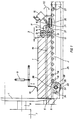
- the product 1 to be cut rests on a roller conveyor 2 which for example inclined at an angle of 45 ° down to the horizontal is, the roller conveyor consist of individual rollers 18, which are parallel are rotatably spaced from each other.
- the product 1 is guided with its front end against a circular knife 4, which is connected to an eccentric 7 via a drive shaft 8, which assigns an eccentric cutting movement to the circular knife 4.
- the circular knife 4 Fixed to the housing, the circular knife 4 is assigned a counter knife 5, which is mounted on a knife bar 6 which is also fixed to the housing.
- the product can optionally be held at the top by a hold-down device 10 are pressed against the counter knife 5, the required for this Pressing force is applied by a pneumatic cylinder 9.
- the feed drive of the product 1 is by a so-called “claw 11 "accomplished, which claw essentially as a drive housing is formed, in the interior of each parallel to each other and superimposed shafts 13 grippers 12 are arranged. Every wave 13 carries a series of one another according to FIG Spacing and parallel to each other Grippers 12, the two shafts via corresponding gears are in engagement with each other and in turn from a gear 17 in the Arrow directions 14 are driven in rotation.
- the gear 17 is driven via a push rod 16, which is acted upon by a pneumatic cylinder 15.
- the feed drive of the claw 11 takes place in that the entire Claw 11 is mounted on a claw rail 21, which in turn in a bearing housing 22 is attached.
- Linear bearings are in the bearing housing 22 23 arranged so that the bearing housing 22 on this linear bearing 23 a prism rail 24 in the feed direction (arrow direction 3) and possibly is movable in the opposite direction.
- a recess 37 is arranged, into which the claw rail 21 inserted and clamped in a manner not shown. In this way, the claw 11 can be easily removed from the claw rail 21 subtracted from.
- the claw 11 is thus in the feed direction 3 intermittently driven in such a way that a precisely defined feed takes place in the direction of the circular knife 4 and the circular knife one cuts precisely defined slice from product 1.
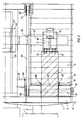
- the feed device consists of a Feed roller 33, which has a toothing 35 on its outer circumference. This toothing 35 digs at least partially in the bottom of the Product 1 a.
- the feed roller 33 is rotatably mounted on an axis 32, which Drive wheel 29 is coupled to the feed roller 33.
- the drive wheel 29 is wrapped by an endless toothed belt 25, which on its other side runs over a rear pulley 27.
- the pulley is rotatably mounted in a housing-fixed holder 28.
- the claw rail 21 is now connected via a clamp 26 the upper or lower run of the toothed belt 25 and thus jammed non-positively coupled.
Landscapes
- Life Sciences & Earth Sciences (AREA)
- Forests & Forestry (AREA)
- Engineering & Computer Science (AREA)
- Mechanical Engineering (AREA)
- Details Of Cutting Devices (AREA)
- Confectionery (AREA)
- Specific Conveyance Elements (AREA)
Description
- Figur 1:
- Seitenansicht einer Vorschubeinrichtung nach der Erfindung,
- Figur 2:
- Draufsicht auf die Vorschubeinrichtung nach Figur 1.
- 1
- Produkt
- 2
- Rollenbahn
- 3
- Pfeilrichtung
- 4
- Kreismesser
- 5
- Gegenmesser
- 6
- Messerbalken
- 7
- Exzenter
- 8
- Antriebswelle
- 9
- Pneumatikzylinder
- 10
- Niederhalter
- 11
- Kralle
- 12
- Greifer
- 13
- Welle
- 14
- Pfeilrichtungen
- 15
- Pneumatikzylinder
- 16
- Schubstange
- 17
- Zahnrad
- 18
- Rolle (Rollenbahn 2)
- 19
- Kugelspindel
- 20
- Pfeilrichtung
- 21
- Krallenschiene
- 22
- Lagergehäuse
- 23
- Linearlager
- 24
- Prismenschiene
- 25
- Zahnriemen
- 26
- Klemmung
- 27
- Umlenkrolle (hinten)
- 28
- Halter
- 29
- Antriebsrad
- 30
- Lagerplatte
- 31
- Distanzblock
- 32
- Achse
- 33
- Vorschubwalze
- 34
- Pfeilrichtung
- 35
- Zahnung
- 36
- Bereich
- 37
- Ausnehmung
- 38
- Seitenführung
Claims (4)
- Vorschubeinrichtung für eine Schneidemaschine zum Schneiden von Lebensmittelprodukten, insbesondere Käse, Wurst und dergleichen, wobei das zu schneidende Produkt (1) auf einer Rollenbahn (2) der Schneidemaschine aufliegt und an seinem hinteren Ende von einer einen Teil der Vorschubeinrichtung bildenden Kralle (11) gehalten ist, die in Vorschubrichtung (3) angetrieben ist und das Produkt (1) in den Schneidebereich eines Kreismessers (4) der Schneidemaschine führt,
dadurch gekennzeichnet,
daß die Vorschubeinrichtung für das Produkt (1) ferner mindestens eine Vorschubwalze (33) umfasst, die kraft- und formschlüssig an der Unterseite des Produkts (1) angreift und in Abhängigkeit vom Vorschubweg der Kralle (11) gekoppelt mit dem Antrieb der Kralle (1) drehend angetrieben ist, wobei die Vorschubwalze (33) im Zwischenraum zwischen dem Ende der Rollenbahn (2) und dem Kreismesser (4) angeordnet ist und über die Rollenebene hinausragt, und der Außenumfang der Vorschubwalze (33) mit einer Zahnung (35) versehen ist, die aus gleichmäßig am Umfang verteilt angeordneten Rippen besteht, deren Längsachse sich senkrecht zur Vorschubrichtung (3) erstreckt. - Vorschubantrieb nach Anspruch 1, dadurch gekennzeichnet, daß der Drehantrieb der Vorschubwalze (33) mit dem Vorschubantrieb der Kralle (11) formschlüssig gekoppelt ist.
- Vorschubantrieb nach Anspruch 2, dadurch gekennzeichnet, daß die formschlüssige Kopplung des Drehantriebes der Vorschubwalze (33) mit dem Vorschubantrieb der Kralle (11) aus einem umlaufenden, geschlossenen Zahnriemen (25) besteht, der einerseits ein mit der Vorschubwalze (33) verbundenes Antriebsrad (29) umschlingt und andererseits über eine am Gehäuse der Schneidemaschine drehbar gelagerte Umlenkrolle (27) geführt ist, wobei eine mit der Kralle (11) verbundene und mit dieser in Vorschubrichtung (3) angetriebene Krallenschiene (21) mit dem oberen Trum des Zahnriemens (25) über eine Klemmung (26) verbunden ist.
- Vorschubantrieb nach Anspruch 1, dadurch gekennzeichnet, daß der Vorschubwalze (33) ein eigener Antrieb zugeordnet ist, der mit dem Vorschubantrieb der Kralle (11) synchronisiert ist.
Applications Claiming Priority (2)
| Application Number | Priority Date | Filing Date | Title |
|---|---|---|---|
| DE9104588U DE9104588U1 (de) | 1991-04-16 | 1991-04-16 | Vorschubantrieb für eine Schneidemaschine zum Schneiden von Lebensmittelprodukten |
| DE9104588U | 1991-04-16 |
Publications (5)
| Publication Number | Publication Date |
|---|---|
| EP0509230A2 EP0509230A2 (de) | 1992-10-21 |
| EP0509230A3 EP0509230A3 (en) | 1993-06-23 |
| EP0509230B1 EP0509230B1 (de) | 1995-09-27 |
| EP0509230B2 true EP0509230B2 (de) | 2000-09-27 |
| EP0509230B9 EP0509230B9 (de) | 2002-03-13 |
Family
ID=6866331
Family Applications (1)
| Application Number | Title | Priority Date | Filing Date |
|---|---|---|---|
| EP92104051A Expired - Lifetime EP0509230B9 (de) | 1991-04-16 | 1992-03-10 | Vorschubantrieb für eine Schneidemaschine zum Schneiden von Lebensmittelprodukten |
Country Status (4)
| Country | Link |
|---|---|
| US (1) | US5191820A (de) |
| EP (1) | EP0509230B9 (de) |
| JP (1) | JPH05104492A (de) |
| DE (2) | DE9104588U1 (de) |
Families Citing this family (23)
| Publication number | Priority date | Publication date | Assignee | Title |
|---|---|---|---|---|
| DE4142009A1 (de) * | 1991-12-19 | 1993-06-24 | Dixie Union Verpackungen Gmbh | Vorschubantrieb fuer schneidmaschinen |
| US5628237A (en) * | 1994-10-11 | 1997-05-13 | Formax, Inc. | Slicing machine for two or more food loaves |
| FR2726779B1 (fr) * | 1994-11-15 | 1996-12-20 | Mecamatic | Installation pour le tranchage de pates en croute et autres aliments presentes en pain |
| DE19801782A1 (de) * | 1998-01-19 | 1999-07-22 | Alpma Alpenland Masch | Verfahren und Vorrichtung zum Transport eines Gegenstands |
| DE29822282U1 (de) * | 1998-12-14 | 2000-04-20 | Dixie-Union GmbH & Co. KG, 87437 Kempten | Schneidmaschine zum Aufschneiden von Lebensmitteln |
| AT409102B (de) * | 2000-03-15 | 2002-05-27 | Kuchler Fritz | Vorschubeinrichtung |
| JP2005193369A (ja) * | 2003-12-09 | 2005-07-21 | Watanabe Foodmach Co Ltd | チョップカッター |
| US7603936B2 (en) * | 2005-03-05 | 2009-10-20 | Formax, Inc. | Loaf seam synchronization device for continuous loaf feed slicing machine |
| DE102005013733A1 (de) * | 2005-03-22 | 2006-10-05 | Reifenhäuser, Uwe, Dipl.-Ing. | Verfahren und Vorrichtung zum Schneiden von strangförmigen Lebensmitteln |
| DE102006014529A1 (de) * | 2006-03-29 | 2007-10-04 | Basf Construction Polymers Gmbh | Verwendung von Fließmitteln auf Basis von Polycarboxylaten für Anyhdrit-basierte Fließestriche |
| US20080016999A1 (en) * | 2006-07-21 | 2008-01-24 | J. E. Grote Company | Dual-mode feed mechanism for a food slicing machine |
| US8336434B2 (en) * | 2007-10-22 | 2012-12-25 | Formax, Inc. | Food article end detection system for a food article slicing machine |
| CA2797849C (en) * | 2010-05-01 | 2017-10-24 | Formax, Inc. | High speed slicing machine |
| JP5481644B2 (ja) * | 2010-07-20 | 2014-04-23 | 株式会社日本キャリア工業 | 食肉スライサーおよび食肉スライス方法 |
| US9597812B2 (en) * | 2012-04-30 | 2017-03-21 | Gea Food Solutions Germany Gmbh | Slicing device comprising a product gripper |
| CN104526755A (zh) * | 2014-12-15 | 2015-04-22 | 梁晋煜 | 一种用于棉制品切片的串联式切割机 |
| CN104742170B (zh) * | 2015-04-10 | 2016-08-24 | 有友食品股份有限公司 | 一种鸡爪切制机用弹性切制装置 |
| DE102015118712A1 (de) * | 2015-11-02 | 2017-05-04 | Textor Maschinenbau GmbH | Vorrichtung zum Aufschneiden von Lebensmittelprodukten |
| CN105252569B (zh) * | 2015-11-09 | 2017-10-27 | 福建佳客来食品股份有限公司 | 牛排全自动砍排机及其砍排方法 |
| JP7539289B2 (ja) * | 2020-10-07 | 2024-08-23 | Toyo Tire株式会社 | ベールゴム保持装置及びベールゴム切断方法 |
| CN112405675A (zh) * | 2020-11-13 | 2021-02-26 | 程加政 | 一种火腿肠加工用切花设备 |
| DE102020133580A1 (de) * | 2020-12-15 | 2022-06-15 | Multivac Sepp Haggenmüller Se & Co. Kg | Aufschneide-Maschine |
| DE102023103039A1 (de) * | 2023-02-08 | 2024-08-08 | Multivac Sepp Haggenmüller Se & Co. Kg | Aufschneide-Maschine |
Family Cites Families (12)
| Publication number | Priority date | Publication date | Assignee | Title |
|---|---|---|---|---|
| US1344118A (en) * | 1919-09-29 | 1920-06-22 | Charles A Dies | Slicing-machine |
| US1445521A (en) * | 1920-08-02 | 1923-02-13 | Us Slicing Machine Co | Slicing machine |
| US1837014A (en) * | 1929-12-19 | 1931-12-15 | American Slicing Machine Co | Slicing machine |
| US1995048A (en) * | 1931-12-04 | 1935-03-19 | Swift & Co | Slicing machine |
| DE683223C (de) * | 1937-10-19 | 1939-11-01 | Alexanderwerk A Von Der Nahmer | Maschine zum Schneiden von Nahrungsmitteln, insbesondere Salat |
| FR898605A (fr) * | 1943-09-10 | 1945-04-27 | Appareil automatique à couper les biscottes | |
| US3200865A (en) * | 1963-04-12 | 1965-08-17 | Wilson & Co Inc | Bacon slicing machine |
| JPS5852074Y2 (ja) * | 1979-04-07 | 1983-11-28 | 南常鉄工株式会社 | 食肉スライサ−の機台 |
| US4329900A (en) * | 1980-01-11 | 1982-05-18 | Cashin Systems Corporation | Bacon slicing machine |
| DE3010733A1 (de) * | 1980-03-20 | 1981-10-01 | Dipl.-Ing. Schindler & Wagner KG, 7067 Plüderhausen | Zwangsfuehrungseinrichtung fuer ein zu zerschneidendes produkt in der nachbarschft der messerscheibe einer schneidmaschine |
| DE3239178A1 (de) * | 1982-10-22 | 1984-04-26 | Natec Reich, Summer GmbH & Co KG, 8999 Heimenkirch | Maschine zum schneiden von schneidgutriegeln |
| DE3912446A1 (de) * | 1989-04-15 | 1990-10-18 | Dixie Union Verpackungen Gmbh | Vorschubvorrichtung an schneidmaschinen |
-
1991
- 1991-04-16 DE DE9104588U patent/DE9104588U1/de not_active Expired - Lifetime
- 1991-06-20 US US07/717,984 patent/US5191820A/en not_active Expired - Fee Related
-
1992
- 1992-03-10 DE DE59203791T patent/DE59203791D1/de not_active Expired - Fee Related
- 1992-03-10 EP EP92104051A patent/EP0509230B9/de not_active Expired - Lifetime
- 1992-04-03 JP JP4082428A patent/JPH05104492A/ja active Pending
Also Published As
| Publication number | Publication date |
|---|---|
| EP0509230B1 (de) | 1995-09-27 |
| EP0509230B9 (de) | 2002-03-13 |
| DE59203791D1 (de) | 1995-11-02 |
| JPH05104492A (ja) | 1993-04-27 |
| DE9104588U1 (de) | 1991-10-17 |
| EP0509230A2 (de) | 1992-10-21 |
| EP0509230A3 (en) | 1993-06-23 |
| US5191820A (en) | 1993-03-09 |
Similar Documents
| Publication | Publication Date | Title |
|---|---|---|
| EP0509230B2 (de) | Vorschubantrieb für eine Schneidemaschine zum Schneiden von Lebensmittelprodukten | |
| DE19518583C2 (de) | Schneidmaschine zum Zerschneiden von Produktlaiben | |
| DE2851683B2 (de) | Vorrichtung zum Schneiden von länglichen Produkten | |
| EP2045053A2 (de) | Scheibenschneidmaschine für strangförmige Lebensmittel | |
| DE19917536A1 (de) | Aufschneidemaschine zum Aufschneiden von Lebensmittelriegeln | |
| EP2226170B1 (de) | Zuführkettenrahmen für automatische Scheibenschneidemaschinen | |
| DE3217038C2 (de) | Verfahren und Vorrichtung zum Ausstanzen eines kontinuierlich bewegten Schneidgutes | |
| EP3912941B1 (de) | Vorrichtung und verfahren zum separieren von schalen aus einem stapel aus mehreren schalen | |
| DE2432361C2 (de) | Vorrichtung zum Zerkleinern von Holz oder holzartigem Material zu Hackschnitzeln | |
| DE19518597A1 (de) | Schneidmaschine | |
| DE2413198A1 (de) | Schneidvorrichtung | |
| DE2054441A1 (de) | Maschine zur Herstellung von Rohwürsten | |
| DE9104580U1 (de) | Zwischenlage-Apparat zur Einbringung von folienartigem Material in die von einer Schneidemaschine geschnittenenen Scheiben | |
| EP1378329A2 (de) | Vorrichtung zur Zuführung von Lebensmitteln zu einer Schneideinrichung und Schneidmaschine für Lebensmittel | |
| DE3327747C2 (de) | Vorrichtung zum Zuführen von stangenförmigem Stückgut | |
| DE2138253A1 (de) | Verpackungsvorrichtung für kontinuierlich angelieferte Artikel, insbesondere Käsescheiben | |
| DE29807384U1 (de) | Vorrichtung für das Einlegen eines Zwischenlegpapiers und Aufschneidmaschine mit einer solchen Vorrichtung | |
| EP0792728B1 (de) | Vorrichtung zum Ablängen von Holz | |
| DE3104099A1 (de) | "wurstfuellmaschine mit vorrichtung zur zipfelbildung" | |
| DE2822771C2 (de) | Vorrichtung zum Herstellen von an den Stirnseiten angefasten Dübeln aus runden Holzstäben | |
| DE9303547U1 (de) | Vorrichtung zum Zerteilen von bahnenförmigem Material | |
| EP4132267A1 (de) | Vorrichtung und verfahren zum längsschneiden eines lebensmittelbandes, insbesondere eines käsebandes, in streifen | |
| EP1058617A1 (de) | Vorrichtung und maschine zur herstellung von polsterartigem verpackungsmaterial | |
| DE102020114060B4 (de) | Schnitzel-Plätter | |
| DE202017102725U1 (de) | Stängelgemüseschneider |
Legal Events
| Date | Code | Title | Description |
|---|---|---|---|
| PUAI | Public reference made under article 153(3) epc to a published international application that has entered the european phase |
Free format text: ORIGINAL CODE: 0009012 |
|
| AK | Designated contracting states |
Kind code of ref document: A2 Designated state(s): CH DE FR GB IT LI |
|
| PUAL | Search report despatched |
Free format text: ORIGINAL CODE: 0009013 |
|
| AK | Designated contracting states |
Kind code of ref document: A3 Designated state(s): CH DE FR GB IT LI |
|
| 17P | Request for examination filed |
Effective date: 19931007 |
|
| RAP1 | Party data changed (applicant data changed or rights of an application transferred) |
Owner name: MASCHINENBAU HEINRICH HAJEK GMBH & CO |
|
| 17Q | First examination report despatched |
Effective date: 19950117 |
|
| GRAA | (expected) grant |
Free format text: ORIGINAL CODE: 0009210 |
|
| AK | Designated contracting states |
Kind code of ref document: B1 Designated state(s): CH DE FR GB IT LI |
|
| REF | Corresponds to: |
Ref document number: 59203791 Country of ref document: DE Date of ref document: 19951102 |
|
| ITF | It: translation for a ep patent filed | ||
| GBT | Gb: translation of ep patent filed (gb section 77(6)(a)/1977) |
Effective date: 19960106 |
|
| ET | Fr: translation filed | ||
| PG25 | Lapsed in a contracting state [announced via postgrant information from national office to epo] |
Ref country code: CH Effective date: 19960331 Ref country code: LI Effective date: 19960331 |
|
| PLBI | Opposition filed |
Free format text: ORIGINAL CODE: 0009260 |
|
| PLBQ | Unpublished change to opponent data |
Free format text: ORIGINAL CODE: EPIDOS OPPO |
|
| PLAV | Examination of admissibility of opposition |
Free format text: ORIGINAL CODE: EPIDOS OPEX |
|
| PLBQ | Unpublished change to opponent data |
Free format text: ORIGINAL CODE: EPIDOS OPPO |
|
| PLBI | Opposition filed |
Free format text: ORIGINAL CODE: 0009260 |
|
| PLAV | Examination of admissibility of opposition |
Free format text: ORIGINAL CODE: EPIDOS OPEX |
|
| PLBF | Reply of patent proprietor to notice(s) of opposition |
Free format text: ORIGINAL CODE: EPIDOS OBSO |
|
| 26 | Opposition filed |
Opponent name: DIXIE-UNION VERPACKUNGEN GMBH Effective date: 19960626 |
|
| 26 | Opposition filed |
Opponent name: DIXIE-UNION VERPACKUNGEN GMBH Effective date: 19960626 Opponent name: FIRMA WEBER MASCHINENBAU GMBH Effective date: 19960627 |
|
| PLBF | Reply of patent proprietor to notice(s) of opposition |
Free format text: ORIGINAL CODE: EPIDOS OBSO |
|
| REG | Reference to a national code |
Ref country code: CH Ref legal event code: PL |
|
| PLAW | Interlocutory decision in opposition |
Free format text: ORIGINAL CODE: EPIDOS IDOP |
|
| APAC | Appeal dossier modified |
Free format text: ORIGINAL CODE: EPIDOS NOAPO |
|
| APAE | Appeal reference modified |
Free format text: ORIGINAL CODE: EPIDOS REFNO |
|
| APAC | Appeal dossier modified |
Free format text: ORIGINAL CODE: EPIDOS NOAPO |
|
| APAE | Appeal reference modified |
Free format text: ORIGINAL CODE: EPIDOS REFNO |
|
| APAC | Appeal dossier modified |
Free format text: ORIGINAL CODE: EPIDOS NOAPO |
|
| PLAW | Interlocutory decision in opposition |
Free format text: ORIGINAL CODE: EPIDOS IDOP |
|
| ITF | It: translation for a ep patent filed | ||
| PUAH | Patent maintained in amended form |
Free format text: ORIGINAL CODE: 0009272 |
|
| STAA | Information on the status of an ep patent application or granted ep patent |
Free format text: STATUS: PATENT MAINTAINED AS AMENDED |
|
| 27A | Patent maintained in amended form |
Effective date: 20000927 |
|
| AK | Designated contracting states |
Kind code of ref document: B2 Designated state(s): CH DE FR GB IT LI |
|
| GBTA | Gb: translation of amended ep patent filed (gb section 77(6)(b)/1977) | ||
| ET3 | Fr: translation filed ** decision concerning opposition | ||
| REG | Reference to a national code |
Ref country code: GB Ref legal event code: IF02 |
|
| PG25 | Lapsed in a contracting state [announced via postgrant information from national office to epo] |
Ref country code: IT Free format text: LAPSE BECAUSE OF NON-PAYMENT OF DUE FEES;WARNING: LAPSES OF ITALIAN PATENTS WITH EFFECTIVE DATE BEFORE 2007 MAY HAVE OCCURRED AT ANY TIME BEFORE 2007. THE CORRECT EFFECTIVE DATE MAY BE DIFFERENT FROM THE ONE RECORDED. Effective date: 20050310 |
|
| APAH | Appeal reference modified |
Free format text: ORIGINAL CODE: EPIDOSCREFNO |
|
| PGFP | Annual fee paid to national office [announced via postgrant information from national office to epo] |
Ref country code: GB Payment date: 20080227 Year of fee payment: 17 |
|
| PLAB | Opposition data, opponent's data or that of the opponent's representative modified |
Free format text: ORIGINAL CODE: 0009299OPPO |
|
| PGFP | Annual fee paid to national office [announced via postgrant information from national office to epo] |
Ref country code: DE Payment date: 20080310 Year of fee payment: 17 |
|
| PGFP | Annual fee paid to national office [announced via postgrant information from national office to epo] |
Ref country code: FR Payment date: 20080327 Year of fee payment: 17 |
|
| GBPC | Gb: european patent ceased through non-payment of renewal fee |
Effective date: 20090310 |
|
| REG | Reference to a national code |
Ref country code: FR Ref legal event code: ST Effective date: 20091130 |
|
| PG25 | Lapsed in a contracting state [announced via postgrant information from national office to epo] |
Ref country code: DE Free format text: LAPSE BECAUSE OF NON-PAYMENT OF DUE FEES Effective date: 20091001 |
|
| PG25 | Lapsed in a contracting state [announced via postgrant information from national office to epo] |
Ref country code: GB Free format text: LAPSE BECAUSE OF NON-PAYMENT OF DUE FEES Effective date: 20090310 Ref country code: FR Free format text: LAPSE BECAUSE OF NON-PAYMENT OF DUE FEES Effective date: 20091123 |
|
| PGFP | Annual fee paid to national office [announced via postgrant information from national office to epo] |
Ref country code: IT Payment date: 20080320 Year of fee payment: 17 |
|
| PGRI | Patent reinstated in contracting state [announced from national office to epo] |
Ref country code: IT Effective date: 20091201 |
|
| PGRI | Patent reinstated in contracting state [announced from national office to epo] |
Ref country code: IT Effective date: 20091201 |