EP0504166B1 - Fahrzeug mit zwei achsen - Google Patents
Fahrzeug mit zwei achsen Download PDFInfo
- Publication number
- EP0504166B1 EP0504166B1 EP90917234A EP90917234A EP0504166B1 EP 0504166 B1 EP0504166 B1 EP 0504166B1 EP 90917234 A EP90917234 A EP 90917234A EP 90917234 A EP90917234 A EP 90917234A EP 0504166 B1 EP0504166 B1 EP 0504166B1
- Authority
- EP
- European Patent Office
- Prior art keywords
- electric motor
- combustion engine
- pulley
- vehicle
- servo
- Prior art date
- Legal status (The legal status is an assumption and is not a legal conclusion. Google has not performed a legal analysis and makes no representation as to the accuracy of the status listed.)
- Expired - Lifetime
Links
Images

Classifications
-
- B—PERFORMING OPERATIONS; TRANSPORTING
- B60—VEHICLES IN GENERAL
- B60K—ARRANGEMENT OR MOUNTING OF PROPULSION UNITS OR OF TRANSMISSIONS IN VEHICLES; ARRANGEMENT OR MOUNTING OF PLURAL DIVERSE PRIME-MOVERS IN VEHICLES; AUXILIARY DRIVES FOR VEHICLES; INSTRUMENTATION OR DASHBOARDS FOR VEHICLES; ARRANGEMENTS IN CONNECTION WITH COOLING, AIR INTAKE, GAS EXHAUST OR FUEL SUPPLY OF PROPULSION UNITS IN VEHICLES
- B60K6/00—Arrangement or mounting of plural diverse prime-movers for mutual or common propulsion, e.g. hybrid propulsion systems comprising electric motors and internal combustion engines
- B60K6/20—Arrangement or mounting of plural diverse prime-movers for mutual or common propulsion, e.g. hybrid propulsion systems comprising electric motors and internal combustion engines the prime-movers consisting of electric motors and internal combustion engines, e.g. HEVs
- B60K6/42—Arrangement or mounting of plural diverse prime-movers for mutual or common propulsion, e.g. hybrid propulsion systems comprising electric motors and internal combustion engines the prime-movers consisting of electric motors and internal combustion engines, e.g. HEVs characterised by the architecture of the hybrid electric vehicle
- B60K6/48—Parallel type
-
- B—PERFORMING OPERATIONS; TRANSPORTING
- B60—VEHICLES IN GENERAL
- B60K—ARRANGEMENT OR MOUNTING OF PROPULSION UNITS OR OF TRANSMISSIONS IN VEHICLES; ARRANGEMENT OR MOUNTING OF PLURAL DIVERSE PRIME-MOVERS IN VEHICLES; AUXILIARY DRIVES FOR VEHICLES; INSTRUMENTATION OR DASHBOARDS FOR VEHICLES; ARRANGEMENTS IN CONNECTION WITH COOLING, AIR INTAKE, GAS EXHAUST OR FUEL SUPPLY OF PROPULSION UNITS IN VEHICLES
- B60K1/00—Arrangement or mounting of electrical propulsion units
- B60K1/04—Arrangement or mounting of electrical propulsion units of the electric storage means for propulsion
-
- B—PERFORMING OPERATIONS; TRANSPORTING
- B60—VEHICLES IN GENERAL
- B60K—ARRANGEMENT OR MOUNTING OF PROPULSION UNITS OR OF TRANSMISSIONS IN VEHICLES; ARRANGEMENT OR MOUNTING OF PLURAL DIVERSE PRIME-MOVERS IN VEHICLES; AUXILIARY DRIVES FOR VEHICLES; INSTRUMENTATION OR DASHBOARDS FOR VEHICLES; ARRANGEMENTS IN CONNECTION WITH COOLING, AIR INTAKE, GAS EXHAUST OR FUEL SUPPLY OF PROPULSION UNITS IN VEHICLES
- B60K6/00—Arrangement or mounting of plural diverse prime-movers for mutual or common propulsion, e.g. hybrid propulsion systems comprising electric motors and internal combustion engines
- B60K6/20—Arrangement or mounting of plural diverse prime-movers for mutual or common propulsion, e.g. hybrid propulsion systems comprising electric motors and internal combustion engines the prime-movers consisting of electric motors and internal combustion engines, e.g. HEVs
- B60K6/50—Architecture of the driveline characterised by arrangement or kind of transmission units
- B60K6/52—Driving a plurality of drive axles, e.g. four-wheel drive
-
- B—PERFORMING OPERATIONS; TRANSPORTING
- B60—VEHICLES IN GENERAL
- B60L—PROPULSION OF ELECTRICALLY-PROPELLED VEHICLES; SUPPLYING ELECTRIC POWER FOR AUXILIARY EQUIPMENT OF ELECTRICALLY-PROPELLED VEHICLES; ELECTRODYNAMIC BRAKE SYSTEMS FOR VEHICLES IN GENERAL; MAGNETIC SUSPENSION OR LEVITATION FOR VEHICLES; MONITORING OPERATING VARIABLES OF ELECTRICALLY-PROPELLED VEHICLES; ELECTRIC SAFETY DEVICES FOR ELECTRICALLY-PROPELLED VEHICLES
- B60L1/00—Supplying electric power to auxiliary equipment of vehicles
- B60L1/003—Supplying electric power to auxiliary equipment of vehicles to auxiliary motors, e.g. for pumps, compressors
-
- B—PERFORMING OPERATIONS; TRANSPORTING
- B60—VEHICLES IN GENERAL
- B60L—PROPULSION OF ELECTRICALLY-PROPELLED VEHICLES; SUPPLYING ELECTRIC POWER FOR AUXILIARY EQUIPMENT OF ELECTRICALLY-PROPELLED VEHICLES; ELECTRODYNAMIC BRAKE SYSTEMS FOR VEHICLES IN GENERAL; MAGNETIC SUSPENSION OR LEVITATION FOR VEHICLES; MONITORING OPERATING VARIABLES OF ELECTRICALLY-PROPELLED VEHICLES; ELECTRIC SAFETY DEVICES FOR ELECTRICALLY-PROPELLED VEHICLES
- B60L50/00—Electric propulsion with power supplied within the vehicle
- B60L50/10—Electric propulsion with power supplied within the vehicle using propulsion power supplied by engine-driven generators, e.g. generators driven by combustion engines
- B60L50/16—Electric propulsion with power supplied within the vehicle using propulsion power supplied by engine-driven generators, e.g. generators driven by combustion engines with provision for separate direct mechanical propulsion
-
- B—PERFORMING OPERATIONS; TRANSPORTING
- B60—VEHICLES IN GENERAL
- B60L—PROPULSION OF ELECTRICALLY-PROPELLED VEHICLES; SUPPLYING ELECTRIC POWER FOR AUXILIARY EQUIPMENT OF ELECTRICALLY-PROPELLED VEHICLES; ELECTRODYNAMIC BRAKE SYSTEMS FOR VEHICLES IN GENERAL; MAGNETIC SUSPENSION OR LEVITATION FOR VEHICLES; MONITORING OPERATING VARIABLES OF ELECTRICALLY-PROPELLED VEHICLES; ELECTRIC SAFETY DEVICES FOR ELECTRICALLY-PROPELLED VEHICLES
- B60L50/00—Electric propulsion with power supplied within the vehicle
- B60L50/50—Electric propulsion with power supplied within the vehicle using propulsion power supplied by batteries or fuel cells
- B60L50/60—Electric propulsion with power supplied within the vehicle using propulsion power supplied by batteries or fuel cells using power supplied by batteries
- B60L50/66—Arrangements of batteries
-
- B—PERFORMING OPERATIONS; TRANSPORTING
- B60—VEHICLES IN GENERAL
- B60L—PROPULSION OF ELECTRICALLY-PROPELLED VEHICLES; SUPPLYING ELECTRIC POWER FOR AUXILIARY EQUIPMENT OF ELECTRICALLY-PROPELLED VEHICLES; ELECTRODYNAMIC BRAKE SYSTEMS FOR VEHICLES IN GENERAL; MAGNETIC SUSPENSION OR LEVITATION FOR VEHICLES; MONITORING OPERATING VARIABLES OF ELECTRICALLY-PROPELLED VEHICLES; ELECTRIC SAFETY DEVICES FOR ELECTRICALLY-PROPELLED VEHICLES
- B60L58/00—Methods or circuit arrangements for monitoring or controlling batteries or fuel cells, specially adapted for electric vehicles
- B60L58/10—Methods or circuit arrangements for monitoring or controlling batteries or fuel cells, specially adapted for electric vehicles for monitoring or controlling batteries
- B60L58/18—Methods or circuit arrangements for monitoring or controlling batteries or fuel cells, specially adapted for electric vehicles for monitoring or controlling batteries of two or more battery modules
-
- B—PERFORMING OPERATIONS; TRANSPORTING
- B61—RAILWAYS
- B61C—LOCOMOTIVES; MOTOR RAILCARS
- B61C7/00—Other locomotives or motor railcars characterised by the type of motive power plant used; Locomotives or motor railcars with two or more different kinds or types of motive power
- B61C7/04—Locomotives or motor railcars with two or more different kinds or types of engines, e.g. steam and IC engines
-
- F—MECHANICAL ENGINEERING; LIGHTING; HEATING; WEAPONS; BLASTING
- F02—COMBUSTION ENGINES; HOT-GAS OR COMBUSTION-PRODUCT ENGINE PLANTS
- F02B—INTERNAL-COMBUSTION PISTON ENGINES; COMBUSTION ENGINES IN GENERAL
- F02B67/00—Engines characterised by the arrangement of auxiliary apparatus not being otherwise provided for, e.g. the apparatus having different functions; Driving auxiliary apparatus from engines, not otherwise provided for
- F02B67/04—Engines characterised by the arrangement of auxiliary apparatus not being otherwise provided for, e.g. the apparatus having different functions; Driving auxiliary apparatus from engines, not otherwise provided for of mechanically-driven auxiliary apparatus
-
- F—MECHANICAL ENGINEERING; LIGHTING; HEATING; WEAPONS; BLASTING
- F16—ENGINEERING ELEMENTS AND UNITS; GENERAL MEASURES FOR PRODUCING AND MAINTAINING EFFECTIVE FUNCTIONING OF MACHINES OR INSTALLATIONS; THERMAL INSULATION IN GENERAL
- F16H—GEARING
- F16H59/00—Control inputs to control units of change-speed- or reversing-gearings for conveying rotary motion
- F16H59/02—Selector apparatus
-
- Y—GENERAL TAGGING OF NEW TECHNOLOGICAL DEVELOPMENTS; GENERAL TAGGING OF CROSS-SECTIONAL TECHNOLOGIES SPANNING OVER SEVERAL SECTIONS OF THE IPC; TECHNICAL SUBJECTS COVERED BY FORMER USPC CROSS-REFERENCE ART COLLECTIONS [XRACs] AND DIGESTS
- Y02—TECHNOLOGIES OR APPLICATIONS FOR MITIGATION OR ADAPTATION AGAINST CLIMATE CHANGE
- Y02T—CLIMATE CHANGE MITIGATION TECHNOLOGIES RELATED TO TRANSPORTATION
- Y02T10/00—Road transport of goods or passengers
- Y02T10/60—Other road transportation technologies with climate change mitigation effect
- Y02T10/62—Hybrid vehicles
-
- Y—GENERAL TAGGING OF NEW TECHNOLOGICAL DEVELOPMENTS; GENERAL TAGGING OF CROSS-SECTIONAL TECHNOLOGIES SPANNING OVER SEVERAL SECTIONS OF THE IPC; TECHNICAL SUBJECTS COVERED BY FORMER USPC CROSS-REFERENCE ART COLLECTIONS [XRACs] AND DIGESTS
- Y02—TECHNOLOGIES OR APPLICATIONS FOR MITIGATION OR ADAPTATION AGAINST CLIMATE CHANGE
- Y02T—CLIMATE CHANGE MITIGATION TECHNOLOGIES RELATED TO TRANSPORTATION
- Y02T10/00—Road transport of goods or passengers
- Y02T10/60—Other road transportation technologies with climate change mitigation effect
- Y02T10/70—Energy storage systems for electromobility, e.g. batteries
-
- Y—GENERAL TAGGING OF NEW TECHNOLOGICAL DEVELOPMENTS; GENERAL TAGGING OF CROSS-SECTIONAL TECHNOLOGIES SPANNING OVER SEVERAL SECTIONS OF THE IPC; TECHNICAL SUBJECTS COVERED BY FORMER USPC CROSS-REFERENCE ART COLLECTIONS [XRACs] AND DIGESTS
- Y02—TECHNOLOGIES OR APPLICATIONS FOR MITIGATION OR ADAPTATION AGAINST CLIMATE CHANGE
- Y02T—CLIMATE CHANGE MITIGATION TECHNOLOGIES RELATED TO TRANSPORTATION
- Y02T10/00—Road transport of goods or passengers
- Y02T10/60—Other road transportation technologies with climate change mitigation effect
- Y02T10/7072—Electromobility specific charging systems or methods for batteries, ultracapacitors, supercapacitors or double-layer capacitors
-
- Y—GENERAL TAGGING OF NEW TECHNOLOGICAL DEVELOPMENTS; GENERAL TAGGING OF CROSS-SECTIONAL TECHNOLOGIES SPANNING OVER SEVERAL SECTIONS OF THE IPC; TECHNICAL SUBJECTS COVERED BY FORMER USPC CROSS-REFERENCE ART COLLECTIONS [XRACs] AND DIGESTS
- Y02—TECHNOLOGIES OR APPLICATIONS FOR MITIGATION OR ADAPTATION AGAINST CLIMATE CHANGE
- Y02T—CLIMATE CHANGE MITIGATION TECHNOLOGIES RELATED TO TRANSPORTATION
- Y02T30/00—Transportation of goods or passengers via railways, e.g. energy recovery or reducing air resistance
-
- Y—GENERAL TAGGING OF NEW TECHNOLOGICAL DEVELOPMENTS; GENERAL TAGGING OF CROSS-SECTIONAL TECHNOLOGIES SPANNING OVER SEVERAL SECTIONS OF THE IPC; TECHNICAL SUBJECTS COVERED BY FORMER USPC CROSS-REFERENCE ART COLLECTIONS [XRACs] AND DIGESTS
- Y10—TECHNICAL SUBJECTS COVERED BY FORMER USPC
- Y10S—TECHNICAL SUBJECTS COVERED BY FORMER USPC CROSS-REFERENCE ART COLLECTIONS [XRACs] AND DIGESTS
- Y10S903/00—Hybrid electric vehicles, HEVS
- Y10S903/902—Prime movers comprising electrical and internal combustion motors
- Y10S903/903—Prime movers comprising electrical and internal combustion motors having energy storing means, e.g. battery, capacitor
- Y10S903/904—Component specially adapted for hev
- Y10S903/915—Specific drive or transmission adapted for hev
- Y10S903/916—Specific drive or transmission adapted for hev with plurality of drive axles
Definitions
- the invention relates to a hybrid vehicle according to the preamble of claim 1.
- Such a vehicle is known from DE-A 30 09 503.
- the hybrid vehicle described there which is operated either with a main motor, which is designed as an electric motor, or with an auxiliary drive motor, which is designed as an internal combustion engine, also has a second electric motor for the auxiliary units, which has a first pulley with the main electric motor and a second pulley is connected to an internal combustion engine.
- the second electric motor ensures a minimum energy for the auxiliary units, but the energy is supplied by the main electric motor or the internal combustion engine under normal conditions.
- hybrid vehicles are known from DE-A 29 29 497 or EP-A 0 004 104.
- Such hybrid cars have an electric motor in addition to the internal combustion engine, and either the electric motor can be switched on if better traction is desired and thus all-wheel drive is generated as a starting aid, or it is switched to exclusive electrical operation if operation with an internal combustion engine is undesirable, e.g. . B. for exhaust gas reasons. Noise pollution is also greatly reduced when operating with an electric motor.
- the generic DE-A 30 09 503 proposes the provision of a second electric motor to maintain the servo functions.
- the object of the invention is to optimally use the components used.
- the second electric motor which is used to drive the additional units during electrical operation, is driven by the internal combustion engine during operation, but is switched as a generator for charging the accumulators.
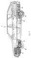
- FIG. 1 shows the side view of the hybrid vehicle 10, which has an internal combustion engine 12 in the front engine compartment with a transmission 14 flanged to it.
- the motor-transmission unit 12 and 14 drives the front axle 16.
- An electric motor 18 is provided on the rear axle and is supplied with power via its own set of batteries 20.
- the electric motor 18 drives the rear axle 22.
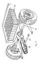
- the rear axle structure is shown in detail in FIG. 2, the electric motor 18, supplied by the accumulators 20, drives the drive shafts 22 via a differential.
- the corresponding brackets for the electric motor 18 are shown, which hang the electric motor 18 in a suitable manner on the frame so that it can take part in the corresponding impact on the rear axle.
- Figure 3 shows the arrangement for driving the servo pump.
- a pulley 30 is driven by the crankshaft of the internal combustion engine, the center of the crankshaft is indicated at 32.
- the rotation of the pulley 30 is transmitted via a V-belt 34 to a pulley 36 which sits on the axis of the servo pump 38 and drives it.
- the pulley 36 has a freewheel so that the power transmission from the pulley 30 to the pulley 36 drives the servo pump 38, whereas a transmission from the pulley 36 to the pulley 30 is not possible due to the freewheel.
- the drive shaft for the servo pump 38 has a further pulley 40 which is connected to a pulley 44 of an electric motor 46 via a V-belt 42.
- the pulley 40 is driven via the electric motor 46 and the V-belt 42 and thus the servo pump 38 is driven to maintain the function of the power steering and the brake booster.
- the motor 46 also runs via the V-belts 34 and 42, only then is the electric motor 46 switched and used as a generator to recharge the batteries 20.
- the batteries 20 can be charged in a preferred manner by dividing them into cells of 12 volts which are connected in parallel and are accordingly charged with a voltage of 12 volts.
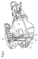
- FIG 4 the elements of the servo pump and servo motor / servo generator are shown in their correct installation in their attachment to the internal combustion engine.
- Reference numeral 50 denotes an internal combustion engine, the crankshaft of which rotates a first pulley 30 and a second pulley 56.
- the pulley 56 is connected to the conventional alternator 52 via a V-belt 54.
- the second pulley 30 rotates the pulley 36 of the servo pump 38 via a V-belt 34, on the same axis sits a second pulley 40 of the servo pump, which is connected to the pulley 44 of the electric motor 46 via the V-belt 42.
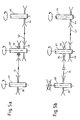
- FIG. 5 shows a freewheel 70 assigned to the pulley 36, which is locked in FIG. 5a.
- This operation corresponds to the operation with an internal combustion engine, so that the shaft 60 assigned to the crankshaft drives the pulley 36 via the pulley 30 and the V-belt 34, which in turn rotates the shaft 62 of the servo pump when the freewheel 70 is locked.
- the electric motor 46 is simultaneously connected as a generator, so that the shaft 46 assigned to it is driven via the pulley 40, which is connected to the shaft 62, and the V-belt 42 and pulley 44.
- the servomotor / generator 46 is thus operated as a generator and generates electricity for recharging the battery unit 20.
- the freewheel 70 is not locked, so that there is no connection between the pulley 36 and the shaft 62.
- This mode of operation corresponds to electrical operation, with the servo motor 46, which now operates as a motor and not as a generator, drives the pulley 40 via its pulley 44 and the V-belt 42, so that the servo pump is driven to maintain the servo functions.
Landscapes
- Engineering & Computer Science (AREA)
- Mechanical Engineering (AREA)
- Transportation (AREA)
- Power Engineering (AREA)
- Combustion & Propulsion (AREA)
- Chemical & Material Sciences (AREA)
- General Engineering & Computer Science (AREA)
- Sustainable Energy (AREA)
- Sustainable Development (AREA)
- Life Sciences & Earth Sciences (AREA)
- Hybrid Electric Vehicles (AREA)
- Vehicle Body Suspensions (AREA)
- Auxiliary Drives, Propulsion Controls, And Safety Devices (AREA)
- Hair Curling (AREA)
- Arrangement Or Mounting Of Control Devices For Change-Speed Gearing (AREA)
- Polymers With Sulfur, Phosphorus Or Metals In The Main Chain (AREA)
- Steering-Linkage Mechanisms And Four-Wheel Steering (AREA)
- Control Of Vehicle Engines Or Engines For Specific Uses (AREA)
- Electric Propulsion And Braking For Vehicles (AREA)
Description
- Die Erfindung betrifft ein Hybridfahrzeug gemäß Oberbegriff des Anspruchs 1.
- Ein derartiges Fahrzeug ist aus der DE-A 30 09 503 bekannt. Das dort beschriebene Hybridfahrzeug, daß entweder mit einem Hauptmotor, der als Elektromotor ausgebildet ist, oder mit einem Hilfsantriebsmotor, der als Brennkraftmaschine ausgelegt ist, betrieben wird, besitzt zusätzlich einen zweiten Elektromotor für die Hilfsaggregate, der über eine erste Riemenscheibe mit dem Hauptelektromotor und über eine zweite Riemenscheibe mit einer Brennkraftmaschine verbunden ist. Der zweite Elektromotor stellt eine Mindestenergie für die Hilfsaggregate sicher, die Energie wird jedoch unter normalen Bedingungen von dem Hauptelektromotor oder der Brennkraftmaschine geliefert.
- Weitere Hybridfahrzeuge sind aus der DE-A 29 29 497 oder der EP-A 0 004 104 bekannt. Derartige Hybridautos besitzen zusätzlich zu der Brennkraftmaschine einen Elektromotor, wobei entweder der Elektromotor zugeschaltet werden kann, wenn eine bessere Traktion erwünscht ist und damit ein Allradantrieb als Anfahrhilfe erzeugt wird, oder es wird auf ausschließlichen Elektrobetrieb umgeschaltet, wenn der Betrieb mit Brennkraftmaschine unerwünscht ist, z. B. aus Abgasgründen. Auch die Geräuschbelästigung ist bei dem Betrieb mit Elektromotor stark vermindert.
- Weiterhin ist es aus der DE-A 23 09 680 bekannt, die Hilfsantriebe für die Aufrechterhaltung der Servofunktionen, wie beispielsweise Bremskraftverstärker, Servolenkung und ähnliche Betriebshilfen, über den Elektromotor anzusteuern. Dazu sind jedoch weitere Keilriemenverbindungen notwendig, was zu einem komplizierteren Aufbau führt. Insbesondere bei den gattungsgemäßen Auslegungen, nämlich eine Zuordnung der Brennkraftmaschine zu der vorderen Achse, während der Elektromotor zu der hinteren Achse zugeordnet wird, sind die beiden Motoren, Brennkraftmaschine und Elektromotor, räumlich so weit voneinander getrennt, daß die Aufrechterhaltungen der Servofunktionen einen erheblichen Bauaufwand bedeutet.
- Die gattungsgemäße DE-A 30 09 503 schlägt zur Aufrechterhaltung der Servofunktionen die Bereitstellung eines zweiten Elektromotors vor.
- Aufgabe der Erfindung ist es, die eingesetzten Komponenten optimal zu verwenden.
- Dazu ist erfindungsgemäß vorgesehen, daß der zweite Elektromotor, der zum Antrieb der zusätzlichen Aggregate während des Elektrobetriebes dient, bei Betrieb durch die Brennkraftmaschine angetrieben wird, jedoch als Generator geschaltet wird zur Aufladung der Akkumulatoren.
- Im weiteren werden einige Aspekte der Erfindung anhand der Zeichnugn näher erläutert. Es zeigen:
- Fig. 1
- eine Seitenansicht des erfindungsgemäßen Fahrzeuges;
- Fig. 2
- die Darstellung der Hinterachse des erfindungsgemäßen Fahrzeuges;
- Fig. 3
- den Antrieb der Servopumpe für das erfindungsgemäße Fahrzeug;
- Fig. 4
- die Darstellung des Antriebes der Servopumpe in Verbindung mit der Brennkraftmaschine;
- Fig. 5
- schematisch die Verbindung zwischen Kurbelwelle, Servopumpe und Servomotor.
- In Fig. 1 ist die Seitenansicht des Hybridfahrzeuges 10 dargestellt, das im vorderen Motorraum eine Brennkraftmaschine 12 mit einem daran angeflanschten Getriebe 14 besitzt. Die Motor-Getriebe-Einheit 12 und 14 treibt die Vorderachse 16 an.
- An der Hinterachse ist ein Elektromotor 18 vorgesehen, der über einen eigenen Satz von Akkumulatoren 20 mit Strom versorgt wird. Der Elektromotor 18 treibt die Hinterachse 22 an.
- Der Hinterachsaufbau ist in Figur 2 detailliert dargestellt, der Elektromotor 18, versorgt aus den Akkumulatoren 20, treibt über ein Differential die Antriebswellen 22 an.
- Mit 24 sind die entsprechenden Halterungen für den Elektromotor 18 dargestellt, die den Elektromotor 18 in geeigneter Weise am Rahmen aufhängen, so daß er die auf die Hinterachse einwirkenden Stöße in entsprechender Form mitmachen kann.
- Figur 3 zeigt die Anordnung zum Antrieb der Servopumpe.
- Eine Riemenscheibe 30 wird von der Kurbelwelle der Brennkraftmaschine angetrieben, die Mitte der Kurbelwelle ist mit 32 angedeutet. Die Drehung der Riemenscheibe 30 wird über einen Keilriemen 34 auf eine Riemenscheibe 36 übertragen, die auf der Achse der Servopumpe 38 sitzt und diese antreibt. Die Riemenscheibe 36 besitzt einen Freilauf, so daß die Kraftübertragung von der Riemenscheibe 30 auf die Riemenscheibe 36 die Servopumpe 38 antreibt, wohingegen eine Übertragung von der Riemenscheibe 36 auf die Riemenscheibe 30 aufgrund des Freilaufes nicht möglich ist.
- Die Antriebswelle für die Servopumpe 38 besitzt eine weitere Riemenscheibe 40, die über einen Keilriemen 42 mit einer Riemenscheibe 44 eines Elektromotors 46 verbunden ist.
- Wenn das Hybridfahrzeug 10 nun im Elektromotorbetrieb, also mit stillgelegter Brennkraftmaschine 12, betrieben wird, wird über den Elektromotor 46 und den Keilriemen 42 die Riemenscheibe 40 angetrieben und somit die Servopumpe 38 zur Erhaltung der Funktion der Servolenkung und der Bremskraftverstärkung angetrieben.
- Dabei ist vorgesehen, daß auch bei Betrieb der Brennkraftmaschine der Motor 46 mitläuft über die Keilriemen 34 und 42, nur wird dann der Elektromotor 46 als Generator geschaltet und verwendet, um die Akkumulatoren 20 wieder aufzuladen.
- Die Aufladung der Akkumulatoren 20 kann in bevorzugter Weise dadurch geschehen, daß diese in Zellen zu 12 Volt aufgeteilt werden, die parallel geschaltet :sind und dementsprechend mit einer Spannung von 12 Volt aufgeladen werden.
- Bei Antrieb des Elektromotors 18 über die Akkumulatoren 20 werden fünf solche Zellen hintereinandergeschaltet um eine Betriebsspannung von 60 Volt zu erreichen, die an den Elektromotor 18 angelegt werden.
- In Figur 4 sind die Elemente Servopumpe und Servomotor/Servogenerator in lagerichtigem Einbau in ihrer Anbringung an der Brennkraftmaschine dargestellt. Mit dem Bezugszeichen 50 ist eine Brennkraftmaschine bezeichnet, deren Kurbelwelle eine erste Riemenscheibe 30 und eine zweite Riemenscheibe 56 dreht. Die Riemenscheibe 56 ist über einen Keilriemen 54 mit der herkömmlichen Lichtmaschine 52 verbunden. Die zweite Riemenscheibe 30 dreht über einen Keilriemen 34 die Riemenscheibe 36 der Servopumpe 38, auf der gleichen Achse sitzt eine zweite Riemenscheibe 40 der Servorpumpe, die über den Keilriemen 42 mit der Riemenscheibe 44 des Elektromotors 46 verbunden ist.
- Diese Riemenscheiben und die zugehörigen antreibenden und angetriebenen Wellen sind schematisch zur Erläuterung in den Figuren 5, 6 und 7 nochmals dargestellt.
- Figur 5 zeigt einen der Riemenscheibe 36 zugeordneten Freilauf 70, der in Figur 5a gesperrt ist. Dieser Betrieb entspricht dem Betrieb mit Brennkraftmaschine, so daß die der Kurbelwelle zugeordnete Welle 60 über die Riemenscheibe 30 und den Keilriemen 34 die Riemenscheibe 36 antreibt, die bei gesperrtem Freilauf 70 wiederum die Welle 62 der Servopumpe dreht. Der Elektromotor 46 ist gleichzeitig als Generator geschaltet, so daß die ihm zugeordnete Welle 46 über die Riemenscheibe 40, die mit der Welle 62 verbunden ist, und den Keilriemen 42 sowie Riemenscheibe 44 angetrieben wird. Damit wird der Servomotor/Generator 46 als Gernerator betrieben und erzeugt Strom zum Nachladen der Batterieeinheit 20.
- In der Betriebsweise gemäß Figur 5b ist der Freilauf 70 nicht gesperrt, so daß zwischen Riemenscheibe 36 und Welle 62 keine Verbindung ist. Diese Betriebsweise entspricht dem Elektrobetrieb, wobei der Servomotor 46, der nunmehr als Motor und nicht als Generator arbeitet, über seine Riemenscheibe 44 und den Keilriemen 42 die Riemenscheibe 40 antreibt, so daß die Servopumpe zur Aufrechterhaltung der Servofunktionen angetrieben ist.
Claims (3)
- Hybridfahrzeug mit einer Brennkraftmaschine und einem Elektromotor zum Antrieb, wobei alternativ das Fahrzeug nur mit Brennkraftmaschine oder nur mit Elektromotor angetrieben wird, und ein zweiter Elektromotor (46) vorgesehen ist, der im Elektrobetrieb die zur Aufrechterhaltung der Servofunktionen notwendigen Aggregate (38) mit Energie versorgt, wobei der zweite Elektromotor (46) genau eine Riemenscheibe (44) zur Übertragung der mechanischen Energie auf die zur Aufrechterhaltung der Servofunktionen notwendigen Aggregate aufweist, dadurch gekennzeichnet, daß das Fahrzeug zwei Achsen besitzt, auf deren eine zum Antrieb die Brennkraftmaschine einwirkt, und deren andere mit Hilfe des Elektromotors angetrieben wird, und bei Betrieb des Fahrzeugs mit Brennkraftmaschine der zweite Elektromotor (46) mitläuft und als Generator zur Wiederaufladung der für die Stromversorgung des Antriebselektromotors (18) vorgesehenen Akkumulatoren (20) eingesetzt wird.
- Fahrzeug nach Anspruch 1, dadurch gekennzeichnet daß die Aggregate eine Pumpe (38) umfassen, die bei Be trieb über die Brennkraftmaschine (12) mit einem von der Brennkraftmaschine angetriebenen Keilriemen (34) und bei Elektrobetrieb über einen von dem zweiten Elektromotor (46) betriebenen Keilriemen (42) bewegt wird.
- Fahrzeug nach Anspruch 2, dadurch gekennzeichnet, daß mindestens eine der Keilriemenscheiben (36, 40) für die Pumpe (38) einen Freilauf aufweist.
Applications Claiming Priority (2)
| Application Number | Priority Date | Filing Date | Title |
|---|---|---|---|
| DE3940172 | 1989-12-05 | ||
| DE3940172A DE3940172A1 (de) | 1989-12-05 | 1989-12-05 | Fahrzeug mit zwei achsen |
Publications (2)
| Publication Number | Publication Date |
|---|---|
| EP0504166A1 EP0504166A1 (de) | 1992-09-23 |
| EP0504166B1 true EP0504166B1 (de) | 1993-08-11 |
Family
ID=6394836
Family Applications (2)
| Application Number | Title | Priority Date | Filing Date |
|---|---|---|---|
| EP91900770A Expired - Lifetime EP0504232B1 (de) | 1989-12-05 | 1990-11-30 | Fahrzeug mit zwei achsen |
| EP90917234A Expired - Lifetime EP0504166B1 (de) | 1989-12-05 | 1990-11-30 | Fahrzeug mit zwei achsen |
Family Applications Before (1)
| Application Number | Title | Priority Date | Filing Date |
|---|---|---|---|
| EP91900770A Expired - Lifetime EP0504232B1 (de) | 1989-12-05 | 1990-11-30 | Fahrzeug mit zwei achsen |
Country Status (7)
| Country | Link |
|---|---|
| US (1) | US5249637A (de) |
| EP (2) | EP0504232B1 (de) |
| JP (2) | JPH05502638A (de) |
| AT (2) | ATE92858T1 (de) |
| DE (3) | DE3940172A1 (de) |
| DK (2) | DK0504232T3 (de) |
| WO (2) | WO1991008123A1 (de) |
Families Citing this family (56)
| Publication number | Priority date | Publication date | Assignee | Title |
|---|---|---|---|---|
| DE4115306A1 (de) | 1991-05-10 | 1992-11-12 | Audi Ag | Zweiachsiges kraftfahrzeug |
| DE4128297C1 (en) * | 1991-08-27 | 1992-12-24 | Manfred 4100 Duisburg De Sonntag | Hybrid drive motor vehicle using IC engine and electromotor - has solar cells for charging batteries to power motor and regenerative drive in parallel with crankshaft of IC engine |
| US5327987A (en) * | 1992-04-02 | 1994-07-12 | Abdelmalek Fawzy T | High efficiency hybrid car with gasoline engine, and electric battery powered motor |
| DE4306381C2 (de) * | 1992-05-09 | 1997-08-21 | Daimler Benz Ag | Hybridantrieb für ein Kraftfahrzeug |
| JPH05328521A (ja) * | 1992-05-15 | 1993-12-10 | Mitsubishi Motors Corp | ハイブリッド車の運転方法 |
| US5558173A (en) * | 1993-09-23 | 1996-09-24 | General Motors Corporation | Integrated hybrid transmission with mechanical accessory drive |
| JPH07242152A (ja) * | 1994-03-07 | 1995-09-19 | Aichi Sangyo Kk | 車両の荷台の下部に取り付けた電源装置 |
| JP3211626B2 (ja) * | 1994-06-29 | 2001-09-25 | トヨタ自動車株式会社 | ハイブリッド車 |
| CA2146394A1 (en) * | 1995-04-05 | 1996-10-06 | Kazutoshi Furukawa | Power supply apparatus installed under a carrier of a vehicle |
| JP3652403B2 (ja) * | 1995-05-01 | 2005-05-25 | 本田技研工業株式会社 | 前後輪駆動車両 |
| JP3681786B2 (ja) * | 1995-05-01 | 2005-08-10 | 本田技研工業株式会社 | 前後輪駆動車両 |
| US5704440A (en) * | 1995-05-31 | 1998-01-06 | New York Institute Of Technology | Energy distribution method for hydrid electric vehicle |
| US5667029A (en) * | 1995-05-31 | 1997-09-16 | New York Institute Of Technology | Drive system for hybrid electric vehicle |
| JP3609491B2 (ja) * | 1995-06-19 | 2005-01-12 | 本田技研工業株式会社 | 前後輪駆動車両 |
| US5658013A (en) * | 1995-09-20 | 1997-08-19 | The Babcock & Wilcox Company | Fuel tank for vehicles for holding and dispensing both a liquid and gaseous fuel therein |
| US5673939A (en) * | 1995-09-20 | 1997-10-07 | The Babcock & Wilcox Company | Fuel tank for storing and dispensing hydrogen and oxygen gas to a fuel cell |
| US5713425A (en) * | 1996-01-16 | 1998-02-03 | Ford Global Technologies, Inc. | Parallel hybrid powertrain for an automotive vehicle |
| US5845731A (en) * | 1996-07-02 | 1998-12-08 | Chrysler Corporation | Hybrid motor vehicle |
| US5971088A (en) * | 1997-03-20 | 1999-10-26 | Smith; Karl R. | Battery charging apparatus |
| JP3685920B2 (ja) * | 1997-09-14 | 2005-08-24 | 本田技研工業株式会社 | ハイブリッド車用電動機制御装置 |
| US6367570B1 (en) | 1997-10-17 | 2002-04-09 | Electromotive Inc. | Hybrid electric vehicle with electric motor providing strategic power assist to load balance internal combustion engine |
| US6053266A (en) | 1997-12-01 | 2000-04-25 | Dbb Fuel Cell Engines Gmbh | Fuel cell engine having a propulsion motor operatively connected to drive a fluid supply device |
| JPH11280512A (ja) * | 1998-03-30 | 1999-10-12 | Nissan Motor Co Ltd | ハイブリッド車両 |
| FR2778873B1 (fr) * | 1998-05-20 | 2000-07-28 | Pierre Guimbretiere | Vehicule automobile a generateurs mecanique et electrique |
| US6338391B1 (en) | 1999-03-01 | 2002-01-15 | Paice Corporation | Hybrid vehicles incorporating turbochargers |
| US6554088B2 (en) | 1998-09-14 | 2003-04-29 | Paice Corporation | Hybrid vehicles |
| US6209672B1 (en) | 1998-09-14 | 2001-04-03 | Paice Corporation | Hybrid vehicle |
| US6892840B2 (en) | 1999-05-05 | 2005-05-17 | Daniel J. Meaney, Jr. | Hybrid electric vehicle having alternate power sources |
| US6307277B1 (en) * | 2000-04-18 | 2001-10-23 | General Motors Corporation | Apparatus and method for a torque and fuel control system for a hybrid vehicle |
| US6612386B2 (en) | 2001-05-30 | 2003-09-02 | General Motors Corporation | Apparatus and method for controlling a hybrid vehicle |
| US20050039964A1 (en) * | 2003-08-19 | 2005-02-24 | Louis Goyry | Hybrid vehicle |
| JP4517708B2 (ja) * | 2004-04-16 | 2010-08-04 | 日産自動車株式会社 | 燃料電池システムの車両搭載構造 |
| US7874389B2 (en) | 2004-11-23 | 2011-01-25 | Hitachi Global Storage Technologies, Netherlands, B.V. | Flexible hybrid drive system for vehicle stability control |
| US7954580B2 (en) * | 2006-03-10 | 2011-06-07 | GM Global Technology Operations LLC | Accessory drive system and method for a belt-alternator-starter electric hybrid vehicle |
| US20070261902A1 (en) * | 2006-05-15 | 2007-11-15 | George Margoudakis | Electric motor vehicle |
| DE102006026916A1 (de) * | 2006-06-09 | 2008-02-07 | Dr.Ing.H.C. F. Porsche Ag | Kraftfahrzeug |
| US20090000836A1 (en) * | 2007-06-30 | 2009-01-01 | Paul Harriman Kydd | Balanced Belt or Chain Drive for Electric Hybrid Vehicle Conversion |
| FR2936393A1 (fr) * | 2008-09-22 | 2010-03-26 | Peugeot Citroen Automobiles Sa | Dispositif de refroidissement par carburant d'un systeme electrique |
| US8251164B2 (en) * | 2009-02-05 | 2012-08-28 | GM Global Technology Operations LLC | Hybrid vehicle drive system |
| CN101531133B (zh) * | 2009-03-12 | 2012-09-19 | 上海汽车集团股份有限公司 | 混合动力汽车的发动机曲轴皮带轮系统 |
| US20100294579A1 (en) * | 2009-05-25 | 2010-11-25 | Chen Fei-Neng | Auto-charging power device and electric vehicle with auto-charging power device |
| MX2012003116A (es) | 2009-09-15 | 2012-06-19 | Kpit Cummins Infosystems Ltd | Asistencia a motor para un vehiculo hibrido a base de entrada de usuario. |
| MX2012003114A (es) | 2009-09-15 | 2012-06-19 | Kpit Cummins Infosystems Ltd | Metodo para convertir un vehiculo en un vehiculo hibrido. |
| CN102596672B (zh) | 2009-09-15 | 2015-03-04 | Kpit技术有限责任公司 | 根据预测的驱动变化向一种混合动力交通工具提供的引擎辅助 |
| US8423214B2 (en) | 2009-09-15 | 2013-04-16 | Kpit Cummins Infosystems, Ltd. | Motor assistance for a hybrid vehicle |
| EP2501576B1 (de) * | 2009-11-18 | 2013-08-21 | Benteler Aluminium Systems France SNC | Batterieträger für ein fahrzeug und verfahren zur herstellung des batterieträgers |
| DE102010021044B4 (de) | 2010-05-19 | 2024-01-11 | Dr. Ing. H.C. F. Porsche Aktiengesellschaft | Mildhybrid-Fahrzeug |
| EP2388897A1 (de) * | 2010-05-21 | 2011-11-23 | Peter Andrew John May | Drehmomentverstärkervorrichtung |
| JP5081969B2 (ja) * | 2010-12-06 | 2012-11-28 | トヨタ自動車株式会社 | ハイブリッド駆動装置およびハイブリッド駆動装置の制御装置 |
| US20120152644A1 (en) * | 2010-12-20 | 2012-06-21 | Paul Harriman Kydd | Compliant, balanced belt or chain drive |
| JP5903277B2 (ja) * | 2012-01-10 | 2016-04-13 | 本田技研工業株式会社 | 車両用駆動装置 |
| US20130228387A1 (en) * | 2012-01-24 | 2013-09-05 | Ford Global Technologies, Llc | Drive Battery Arrangement and Motor Vehicle Having a Drive Battery Arrangement |
| JP5983054B2 (ja) * | 2012-06-04 | 2016-08-31 | スズキ株式会社 | ハイブリッド自動車のバッテリパック冷却構造 |
| RU2656940C1 (ru) * | 2017-04-04 | 2018-06-07 | федеральное государственное автономное образовательное учреждение высшего образования "Санкт-Петербургский политехнический университет Петра Великого" (ФГАОУ ВО "СПбПУ") | Привод электрического генератора в составе самоходного наземного транспортного средства |
| DE102017206516B4 (de) * | 2017-04-18 | 2024-04-25 | Magna powertrain gmbh & co kg | Antriebsstrang für ein Hybridfahrzeug, insbesondere für ein zeitweise vierradgetriebenes Kraftfahrzeug |
| DE102020200900A1 (de) | 2020-01-27 | 2021-07-29 | Zf Friedrichshafen Ag | Hybrid-Schienenfahrzeug |
Family Cites Families (15)
| Publication number | Priority date | Publication date | Assignee | Title |
|---|---|---|---|---|
| DE178513C (de) * | ||||
| GB1270764A (en) * | 1970-03-23 | 1972-04-12 | Kosuke Matsukata | Improvements in or relating to road vehicles |
| DE2309680A1 (de) * | 1973-02-27 | 1974-09-05 | Elektr Strassenverkehr Ges | Kraftfahrzeug mit verbrennungsmotor, elektromotor mit batterie und steuereinrichtung |
| DE2400760A1 (de) * | 1974-01-08 | 1975-09-04 | Karl Friedel | Kombiniertes kraftstoff-elektrofahrzeug als pkw |
| DE2501386A1 (de) * | 1975-01-15 | 1976-07-22 | Louis L Lepoix | Hybrid-antrieb fuer fahrzeuge, insbesondere kraftfahrzeuge |
| US4042056A (en) * | 1975-11-21 | 1977-08-16 | Automobile Corporation Of America | Hybrid powered automobile |
| US4180138A (en) * | 1977-09-30 | 1979-12-25 | Dana Corporation | Vehicle having auxiliary drive mechanism |
| EP0004194A1 (de) * | 1978-03-13 | 1979-09-19 | Hybricon, Inc. | Hybrid-Kraftfahrzeug mit Elektro- und Verbrennungsmotor |
| FR2461610A1 (fr) * | 1979-07-16 | 1981-02-06 | Dana Corp | Vehicule a moteur auxiliaire |
| DE3009503A1 (de) * | 1980-03-12 | 1981-09-17 | Maschf Augsburg Nuernberg Ag | Hybridantriebsvorrichtung fuer nutzfahrzeuge |
| JPS58116229A (ja) * | 1981-12-30 | 1983-07-11 | Isuzu Motors Ltd | 車載用油圧源の駆動装置 |
| JPS58118424A (ja) * | 1981-12-30 | 1983-07-14 | Isuzu Motors Ltd | 車載用油圧源の駆動装置 |
| DE3246230A1 (de) * | 1982-12-14 | 1984-06-14 | Volkswagenwerk Ag | Getriebeanordnung |
| DE3617256A1 (de) * | 1986-05-22 | 1987-11-26 | Audi Ag | Vorrichtung an einem kraftfahrzeug |
| US4854193A (en) * | 1988-03-25 | 1989-08-08 | Babcock Industries Inc. | Key interlock system for automatic floor mounted transmission shifter |
-
1989
- 1989-12-05 DE DE3940172A patent/DE3940172A1/de not_active Withdrawn
-
1990
- 1990-11-30 DE DE9191900770T patent/DE59001814D1/de not_active Expired - Fee Related
- 1990-11-30 US US07/852,213 patent/US5249637A/en not_active Expired - Fee Related
- 1990-11-30 AT AT90917234T patent/ATE92858T1/de not_active IP Right Cessation
- 1990-11-30 WO PCT/EP1990/002059 patent/WO1991008123A1/de not_active Ceased
- 1990-11-30 WO PCT/EP1990/002058 patent/WO1991008122A1/de not_active Ceased
- 1990-11-30 JP JP3501210A patent/JPH05502638A/ja active Pending
- 1990-11-30 DK DK91900770.8T patent/DK0504232T3/da active
- 1990-11-30 AT AT91900770T patent/ATE90626T1/de not_active IP Right Cessation
- 1990-11-30 DE DE9090917234T patent/DE59002350D1/de not_active Expired - Fee Related
- 1990-11-30 EP EP91900770A patent/EP0504232B1/de not_active Expired - Lifetime
- 1990-11-30 EP EP90917234A patent/EP0504166B1/de not_active Expired - Lifetime
- 1990-11-30 DK DK90917234.8T patent/DK0504166T3/da active
- 1990-11-30 JP JP3500123A patent/JPH05503050A/ja not_active Withdrawn
Non-Patent Citations (2)
| Title |
|---|
| PATENT ABSTRACTS OF JAPAN, Band 7, N. 223, M247, 14. Juli 1983 * |
| PATENT ABSTRACTS OF JAPAN, Band 7, Nr. 221, M246, 11. Juli 1983 * |
Also Published As
| Publication number | Publication date |
|---|---|
| DK0504166T3 (da) | 1993-10-18 |
| JPH05502638A (ja) | 1993-05-13 |
| WO1991008123A1 (de) | 1991-06-13 |
| EP0504232B1 (de) | 1993-06-16 |
| US5249637A (en) | 1993-10-05 |
| DE59002350D1 (de) | 1993-09-16 |
| DE59001814D1 (de) | 1993-07-22 |
| EP0504166A1 (de) | 1992-09-23 |
| DK0504232T3 (da) | 1993-07-12 |
| EP0504232A1 (de) | 1992-09-23 |
| WO1991008122A1 (de) | 1991-06-13 |
| JPH05503050A (ja) | 1993-05-27 |
| ATE92858T1 (de) | 1993-08-15 |
| DE3940172A1 (de) | 1991-06-06 |
| ATE90626T1 (de) | 1993-07-15 |
Similar Documents
| Publication | Publication Date | Title |
|---|---|---|
| EP0504166B1 (de) | Fahrzeug mit zwei achsen | |
| DE69418023T2 (de) | Verschiedene Kopplungs- und Verbund- Leistungssysteme vom elektrischen Übertragungs- und Speichertyp | |
| EP1069310B1 (de) | Antriebsvorrichtung | |
| EP3326852B1 (de) | Motorsteuerung von fahrzeugen mit mehreren e-maschinen | |
| DE102020105843A1 (de) | Antriebseinrichtung für ein Kraftfahrzeug | |
| DE102018114782A1 (de) | Antriebseinheit und Antriebsanordnung | |
| EP1185430B1 (de) | Antriebsvorrichtung für wenigstens ein nebenaggregat | |
| DE102011102265A1 (de) | Anordnung eines Antriebsstrangs an einem Aufbau eines Kraftwagens | |
| EP2218603A1 (de) | Hybridantrieb | |
| EP0082932A2 (de) | Antriebsbaugruppe für Kraftfahrzeuge mit einem Elektromotor und einem Verbrennungsmotor | |
| DE102021114919B4 (de) | Antriebseinheit und Antriebsanordnung | |
| DE102016007702A1 (de) | Nutzfahrzeug mit einem Parallel-Hybrid-Antriebsstrang | |
| DE102008044035B4 (de) | Allrad-Hybridantriebsstrang für ein Kraftfahrzeug und Verfahren zum Betreiben des Hybridantriebsstrangs | |
| DE102020216247A1 (de) | Verfahren zum Antrieb eines zumindest teilweise elektrisch angetriebenen Fahrzeugs sowie Getriebeanordnung und Antriebsvorrichtung für ein solches Fahrzeug | |
| DE102019212476A1 (de) | Antriebssystem | |
| DE102011088208A1 (de) | Verfahren zum Steuern eines Hybridfahrzeugs | |
| DE10141740B4 (de) | Kraftfahrzeug mit einem Brennstoffzellensystem | |
| DE102011013759A1 (de) | Rein elektrisch getriebener Antriebstrang für ein Fahrzeug | |
| DE19907852A1 (de) | Generatorsystem | |
| DE10257257A1 (de) | Angetriebenes Fahrzeug | |
| DE10338159B4 (de) | Spannungsversorgungseinrichtung und Verfahren zur Spannungserzeugung in einem Kraftfahrzeug | |
| DE102019008222A1 (de) | Antriebseinrichtung für einen Kraftwagen, insbesondere für ein Nutzfahrzeug | |
| DE102012214200A1 (de) | Elektrische Maschine für ein System zur Klimatisierung, elektrische Maschine, Steuerung, System und Verfahren zur Klimatisierung eines Kraftfahrzeugs | |
| DE102010021044B4 (de) | Mildhybrid-Fahrzeug | |
| DE102022120598A1 (de) | Verfahren zum Betreiben eines Kraftfahrzeugs und Kraftfahrzeug mit einer Hauptantriebsachse und einer Nebenantriebsachse |
Legal Events
| Date | Code | Title | Description |
|---|---|---|---|
| PUAI | Public reference made under article 153(3) epc to a published international application that has entered the european phase |
Free format text: ORIGINAL CODE: 0009012 |
|
| 17P | Request for examination filed |
Effective date: 19920302 |
|
| AK | Designated contracting states |
Kind code of ref document: A1 Designated state(s): AT CH DE DK FR GB IT LI |
|
| 17Q | First examination report despatched |
Effective date: 19921124 |
|
| ITF | It: translation for a ep patent filed | ||
| GRAA | (expected) grant |
Free format text: ORIGINAL CODE: 0009210 |
|
| AK | Designated contracting states |
Kind code of ref document: B1 Designated state(s): AT CH DE DK FR GB IT LI |
|
| REF | Corresponds to: |
Ref document number: 92858 Country of ref document: AT Date of ref document: 19930815 Kind code of ref document: T |
|
| REF | Corresponds to: |
Ref document number: 59002350 Country of ref document: DE Date of ref document: 19930916 |
|
| GBT | Gb: translation of ep patent filed (gb section 77(6)(a)/1977) |
Effective date: 19930826 |
|
| REG | Reference to a national code |
Ref country code: DK Ref legal event code: T3 |
|
| ET | Fr: translation filed | ||
| PLBE | No opposition filed within time limit |
Free format text: ORIGINAL CODE: 0009261 |
|
| STAA | Information on the status of an ep patent application or granted ep patent |
Free format text: STATUS: NO OPPOSITION FILED WITHIN TIME LIMIT |
|
| 26N | No opposition filed | ||
| PGFP | Annual fee paid to national office [announced via postgrant information from national office to epo] |
Ref country code: DK Payment date: 19961120 Year of fee payment: 7 |
|
| PG25 | Lapsed in a contracting state [announced via postgrant information from national office to epo] |
Ref country code: DK Free format text: LAPSE BECAUSE OF NON-PAYMENT OF DUE FEES Effective date: 19971231 |
|
| REG | Reference to a national code |
Ref country code: GB Ref legal event code: IF02 |
|
| REG | Reference to a national code |
Ref country code: DK Ref legal event code: EBP |
|
| PGFP | Annual fee paid to national office [announced via postgrant information from national office to epo] |
Ref country code: DE Payment date: 20021102 Year of fee payment: 13 |
|
| PGFP | Annual fee paid to national office [announced via postgrant information from national office to epo] |
Ref country code: FR Payment date: 20021119 Year of fee payment: 13 |
|
| PGFP | Annual fee paid to national office [announced via postgrant information from national office to epo] |
Ref country code: AT Payment date: 20021122 Year of fee payment: 13 |
|
| PGFP | Annual fee paid to national office [announced via postgrant information from national office to epo] |
Ref country code: CH Payment date: 20021126 Year of fee payment: 13 |
|
| PGFP | Annual fee paid to national office [announced via postgrant information from national office to epo] |
Ref country code: GB Payment date: 20031027 Year of fee payment: 14 |
|
| PG25 | Lapsed in a contracting state [announced via postgrant information from national office to epo] |
Ref country code: LI Free format text: LAPSE BECAUSE OF NON-PAYMENT OF DUE FEES Effective date: 20031130 Ref country code: CH Free format text: LAPSE BECAUSE OF NON-PAYMENT OF DUE FEES Effective date: 20031130 Ref country code: AT Free format text: LAPSE BECAUSE OF NON-PAYMENT OF DUE FEES Effective date: 20031130 |
|
| PG25 | Lapsed in a contracting state [announced via postgrant information from national office to epo] |
Ref country code: DE Free format text: LAPSE BECAUSE OF NON-PAYMENT OF DUE FEES Effective date: 20040602 |
|
| REG | Reference to a national code |
Ref country code: CH Ref legal event code: PL |
|
| PG25 | Lapsed in a contracting state [announced via postgrant information from national office to epo] |
Ref country code: FR Free format text: LAPSE BECAUSE OF NON-PAYMENT OF DUE FEES Effective date: 20040730 |
|
| REG | Reference to a national code |
Ref country code: FR Ref legal event code: ST |
|
| PG25 | Lapsed in a contracting state [announced via postgrant information from national office to epo] |
Ref country code: GB Free format text: LAPSE BECAUSE OF NON-PAYMENT OF DUE FEES Effective date: 20041130 |
|
| GBPC | Gb: european patent ceased through non-payment of renewal fee |
Effective date: 20041130 |
|
| PG25 | Lapsed in a contracting state [announced via postgrant information from national office to epo] |
Ref country code: IT Free format text: LAPSE BECAUSE OF NON-PAYMENT OF DUE FEES;WARNING: LAPSES OF ITALIAN PATENTS WITH EFFECTIVE DATE BEFORE 2007 MAY HAVE OCCURRED AT ANY TIME BEFORE 2007. THE CORRECT EFFECTIVE DATE MAY BE DIFFERENT FROM THE ONE RECORDED. Effective date: 20051130 |