EP0492468A2 - Aktive Aufhängung mit verändlichem Verteilungsverhältnis der Rollsteifigkeit - Google Patents
Aktive Aufhängung mit verändlichem Verteilungsverhältnis der Rollsteifigkeit Download PDFInfo
- Publication number
- EP0492468A2 EP0492468A2 EP91121854A EP91121854A EP0492468A2 EP 0492468 A2 EP0492468 A2 EP 0492468A2 EP 91121854 A EP91121854 A EP 91121854A EP 91121854 A EP91121854 A EP 91121854A EP 0492468 A2 EP0492468 A2 EP 0492468A2
- Authority
- EP
- European Patent Office
- Prior art keywords
- vehicle
- vehicle wheel
- transverse acceleration
- factor
- working fluid
- Prior art date
- Legal status (The legal status is an assumption and is not a legal conclusion. Google has not performed a legal analysis and makes no representation as to the accuracy of the status listed.)
- Granted
Links
Images


Classifications
-
- B—PERFORMING OPERATIONS; TRANSPORTING
- B60—VEHICLES IN GENERAL
- B60G—VEHICLE SUSPENSION ARRANGEMENTS
- B60G17/00—Resilient suspensions having means for adjusting the spring or vibration-damper characteristics, for regulating the distance between a supporting surface and a sprung part of vehicle or for locking suspension during use to meet varying vehicular or surface conditions, e.g. due to speed or load
- B60G17/015—Resilient suspensions having means for adjusting the spring or vibration-damper characteristics, for regulating the distance between a supporting surface and a sprung part of vehicle or for locking suspension during use to meet varying vehicular or surface conditions, e.g. due to speed or load the regulating means comprising electric or electronic elements
- B60G17/016—Resilient suspensions having means for adjusting the spring or vibration-damper characteristics, for regulating the distance between a supporting surface and a sprung part of vehicle or for locking suspension during use to meet varying vehicular or surface conditions, e.g. due to speed or load the regulating means comprising electric or electronic elements characterised by their responsiveness, when the vehicle is travelling, to specific motion, a specific condition, or driver input
- B60G17/0162—Resilient suspensions having means for adjusting the spring or vibration-damper characteristics, for regulating the distance between a supporting surface and a sprung part of vehicle or for locking suspension during use to meet varying vehicular or surface conditions, e.g. due to speed or load the regulating means comprising electric or electronic elements characterised by their responsiveness, when the vehicle is travelling, to specific motion, a specific condition, or driver input mainly during a motion involving steering operation, e.g. cornering, overtaking
-
- B—PERFORMING OPERATIONS; TRANSPORTING
- B60—VEHICLES IN GENERAL
- B60G—VEHICLE SUSPENSION ARRANGEMENTS
- B60G2400/00—Indexing codes relating to detected, measured or calculated conditions or factors
- B60G2400/10—Acceleration; Deceleration
- B60G2400/104—Acceleration; Deceleration lateral or transversal with regard to vehicle
-
- B—PERFORMING OPERATIONS; TRANSPORTING
- B60—VEHICLES IN GENERAL
- B60G—VEHICLE SUSPENSION ARRANGEMENTS
- B60G2400/00—Indexing codes relating to detected, measured or calculated conditions or factors
- B60G2400/10—Acceleration; Deceleration
- B60G2400/106—Acceleration; Deceleration longitudinal with regard to vehicle, e.g. braking
-
- B—PERFORMING OPERATIONS; TRANSPORTING
- B60—VEHICLES IN GENERAL
- B60G—VEHICLE SUSPENSION ARRANGEMENTS
- B60G2400/00—Indexing codes relating to detected, measured or calculated conditions or factors
- B60G2400/20—Speed
- B60G2400/204—Vehicle speed
-
- B—PERFORMING OPERATIONS; TRANSPORTING
- B60—VEHICLES IN GENERAL
- B60G—VEHICLE SUSPENSION ARRANGEMENTS
- B60G2400/00—Indexing codes relating to detected, measured or calculated conditions or factors
- B60G2400/25—Stroke; Height; Displacement
- B60G2400/252—Stroke; Height; Displacement vertical
-
- B—PERFORMING OPERATIONS; TRANSPORTING
- B60—VEHICLES IN GENERAL
- B60G—VEHICLE SUSPENSION ARRANGEMENTS
- B60G2400/00—Indexing codes relating to detected, measured or calculated conditions or factors
- B60G2400/60—Load
-
- B—PERFORMING OPERATIONS; TRANSPORTING
- B60—VEHICLES IN GENERAL
- B60G—VEHICLE SUSPENSION ARRANGEMENTS
- B60G2400/00—Indexing codes relating to detected, measured or calculated conditions or factors
- B60G2400/60—Load
- B60G2400/61—Load distribution
-
- B—PERFORMING OPERATIONS; TRANSPORTING
- B60—VEHICLES IN GENERAL
- B60G—VEHICLE SUSPENSION ARRANGEMENTS
- B60G2400/00—Indexing codes relating to detected, measured or calculated conditions or factors
- B60G2400/90—Other conditions or factors
-
- B—PERFORMING OPERATIONS; TRANSPORTING
- B60—VEHICLES IN GENERAL
- B60G—VEHICLE SUSPENSION ARRANGEMENTS
- B60G2600/00—Indexing codes relating to particular elements, systems or processes used on suspension systems or suspension control systems
- B60G2600/60—Signal noise suppression; Electronic filtering means
- B60G2600/604—Signal noise suppression; Electronic filtering means low pass
-
- B—PERFORMING OPERATIONS; TRANSPORTING
- B60—VEHICLES IN GENERAL
- B60G—VEHICLE SUSPENSION ARRANGEMENTS
- B60G2800/00—Indexing codes relating to the type of movement or to the condition of the vehicle and to the end result to be achieved by the control action
- B60G2800/01—Attitude or posture control
- B60G2800/012—Rolling condition
-
- B—PERFORMING OPERATIONS; TRANSPORTING
- B60—VEHICLES IN GENERAL
- B60G—VEHICLE SUSPENSION ARRANGEMENTS
- B60G2800/00—Indexing codes relating to the type of movement or to the condition of the vehicle and to the end result to be achieved by the control action
- B60G2800/24—Steering, cornering
- B60G2800/246—Understeer
Definitions
- the present invention relates to a suspension of a vehicle such as an automobile, and more particularly to a control of an active suspension in relation to a turning of the vehicle.
- a hydraulic active suspension comprising an actuator provided to correspond to each vehicle wheel so as to change vehicle height at a corresponding position according to supply or exhaust of a working fluid to or from a working fluid chamber thereof, a working fluid supply and exhaust means for supplying or exhausting the working fluid to or from said working fluid chamber, a transverse acceleration detection means for detecting transverse acceleration of a vehicle body, a means for detecting load imposed on a vehicle wheel at an outside of a turning, and a control means for controlling said working fluid supply and exhaust means in accordance with said transverse acceleration.
- an attitude change of the vehicle body due to a transverse acceleration during a turning is desirably controlled, as the working fluid supply and exhaust means is controlled according to the transverse acceleration of the vehicle body and vehicle heights at respective vehicle wheels are changed so as to suppress the rolling of the vehicle body.
- the steering performance of a vehicle is determined according to the distribution of the roll rigidity between front and rear vehicle wheels.
- the distribution of the roll rigidity is generally fixed.
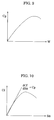
- a load on a vehicle wheel i.e. a tire load (W)
- a cornering power (Cp) shows a saturating characteristic as shown in Fig. 9. Therefore, in a relatively high tire load region, the cornering power does not correspondingly increase when the tire load further increases. Therefore, during a high transverse acceleration turning, the cornering power in a front vehicle wheel at the outside of the turning first saturates so that the relative magnitude of the cornering power in the front vehicle wheel decreases as compared to that in a rear vehicle wheel, whereby the vehicle shifts towards the outside of the turning, with the steering performance shifting toward the understeer.
- W tire load
- Cp cornering power
- the object of the present invention to provide an improved active suspension in which the stability of the vehicle during a normal turning including a lane change and the manoeuvrability of the vehicle during a high transverse acceleration turning are both improved.
- an active suspension comprising actuators provided to correspond to each vehicle wheel so as to change vehicle height at a corresponding position, a transverse acceleration detection means for detecting transverse acceleration of a vehicle body, a means for detecting load imposed on a vehicle wheel at an outside of a turning, and a control means for controlling said actuator in accordance with said transverse acceleration, wherein said control means is adapted to distribute roll rigidity so as to provide a greater share thereof on a rear vehicle wheel as the loads imposed on the vehicle wheels at the outside of the turning is greater.
- the distribution of the roll rigidity is controlled to be shifted more toward the rear vehicle wheels as the load on the vehicle wheels at the outside of a turning is greater, or conversely, is shifted more toward the front vehicle wheels as the load on the vehicle wheels at the outside of a turning is less.
- the distribution of the roll rigidity is controlled to be shifted toward the rear vehicle wheels during a high transverse acceleration turning of the vehicle, the steering performance is shifted toward the oversteer, whereby a good manoeuvrability of the vehicle is ensured.
- the steering performance is shifted toward the understeer, whereby a good stability of the vehicle is ensured.
- said control means may comprise a first factor multiplier for a front vehicle wheel and a second factor multiplier for a rear vehicle wheel, said first and second factor multipliers calculating loads imposed on the front and rear vehicle wheels from the transverse acceleration, respectively, and a function generating system for generating multiplying factors in said first and second factor multipliers based upon at least one of the vehicle wheel loads calculated by said first and second factor multipliers, wherein said function generating system decreases the multiplying factor for the front vehicle wheel relative to the multiplying factor for the rear vehicle wheel as the absolute value of the vehicle wheel load calculated by at least one of said first and second factor multipliers increases.
- said function generating system may comprise a means for restricting said first and second multiplying factors not to be greater than maximum values predetermined therefor and not to be less than minimum values predetermined therefor.
- Said maximum and minimum values for said first and second multiplying factors may desirably be increased when vehicle speed increases.
- the actuator may conveniently be a hydraulic actuator having a working fluid chamber
- said control means may comprise a hydraulic circuit means for supplying and exhausting a working fluid to and from said working fluid chamber, and an electric control means for controlling flow of a working fluid in said hydraulic circuit means.
- 10 designates a reservoir for storing oil operating as a working fluid.
- a connection passage 12 is connected to the reservoir 10 at one end thereof, and a working fluid exhaust passage 14 is also connected at one end thereof to the reservoir 10.
- the connection passage 12 is connected at another end thereof with an intake side of a pump 18 driven by an engine 16.
- the pump 18 is a variable capacity pump, a delivery slide of which is connected with one end of a working fluid supply passage 20.
- Another end of the working fluid supply passage 20 and another end of the working fluid exhaust passage 14 are connected to port P and port R of a pilot operated three ports three positions changeover control valve 24 of a pressure control valve 22, respectively.
- a non return valve 15 which allows a flow of the working fluid only in a direction flowing from the pressure control valve 22 toward the reservoir 10.
- the pressure control valve 22 includes the changeover control valve 24, a connection passage 26 connecting the working fluid supply passage 20 with the reservoir 10, and a fixed throttle means 28 and a variable throttle means 30 provided in succession at a middle portion of the connection passage 26.
- a connection passage 32 is connected to port A of the changeover control valve 24.
- the changeover control valve 24 is a spool valve adapted to be operated by pilot pressures which are pressure Pp existing in the passage 26 at a portion between the fixed throttle means 28 and the variable throttle means 30 and pressure Pa existing in a connection passage 32.
- the changeover control valve 24 is changed over to a changeover position 24a to connect port P with port A when pressure Pp is higher than pressure Pa, to a changeover position 24b to interrupt connection between all the ports when pressure Pp is equal to pressure Pa, and to a changeover position 24c to connect port R with port A when pressure Pp is lower than pressure Pa.
- the variable throttle means 30 changes its effective passage area according to a control electric current supplied to its solenoid so as to change pressure Pp in cooperation with the fixed throttle means 28.
- connection passage 32 is connected at another end thereof with a working fluid chamber 38 of an actuator 36 provided to correspond to a vehicle wheel.
- the actuator 36 is a kind of cylinder-piston means disposed between a suspension member for supporting a vehicle wheel and a vehicle body, both not shown in the figure, so that it increases or decreases the vehicle height at the corresponding position according to supply or exhaust of the working fluid to or from the working fluid chamber 38.
- a gas-liquid spring means 42 is connected to the working fluid chamber 38 via a passage 40.
- a throttle means 44 is provided at a middle portion of the passage 40.
- the gas-liquid spring means 42 operates as a suspension spring or an auxiliary suspension spring, wherein the throttle means 44 generates a damping force.
- An on-off valve 46 is provided at a middle portion of the connection passage 32.
- the on-off valve 46 is constructed to be opened when a pilot pressure Pc supplied thereto from a pilot pressure control means 48 is higher than a predetermined valve opening pressure and to be closed when the pilot pressure is lower than a predetermined valve closing pressure.
- the pilot pressure control means 48 includes a connection passage 50 connecting the working fluid supply passage 20 and the reservoir 10, and a fixed throttle means 52 and a variable throttle means 54 provided in succession at a middle portion of the connection passage 50, wherein the pilot pressure Pc is provided as a pressure between the fixed throttle means and the variable throttle means.
- a non return valve 58 is provided at a middle portion of the working fluid supply passage 20 so as to allow the working fluid to flow only from the pump 18 toward the pressure control valve 22 through a filter 58. Further, an accumulator 60 is connected to the working fluid supply passage 20 at the downstream side of the non return valve 58.
- non return valve 15, the pressure control valve 22, the connection passage 32, the throttle means 44, the on-off valve 46, the actuator 36, the gas-liquid spring means 42, etc. are each provided to correspond to each vehicle wheel.
- the pressure control valves corresponding to front right, front left, rear right and rear left vehicle wheels are designated by 22fr, 22fl, 22rr and 22rl, respectively.
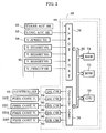
- the pressure control valve 22 is controlled by an electric control means 66 shown in Fig. 2.
- the electric control means 66 comprises a micro computer 68 which may have a common construction as shown in Fig. 2, including a central processing unit (CPU) 70, a read only memory (ROM) 72, a random access memory (RAM) 74, an input port means 76, an output port means 78 and a common bus 80.
- CPU central processing unit
- ROM read only memory
- RAM random access memory
- the input port means 76 is inputted with a signal representing transverse acceleration Gx (positive when directed leftward) of a vehicle body from a transverse acceleration sensor 62, a signal representing longitudinal acceleration Gy (positive when directed forward) of the vehicle body from a longitudinal acceleration sensor 62, a signal representing vehicle speed V from a vehicle speed sensor 64, signals representing vehicle heights corresponding to respective vehicle wheels from vehicle wheel sensors 65 and others, concerned with the running condition of the vehicle.
- the input port means 76 processes these input signals appropriately and supplies the processed signals to CPU 70 and RAM 74 according to the instructions from CPU 70 based upon a program stored in ROM 72.
- ROM 72 stores such a control program, such maps as shown in Figs. 4 and 5, and so on.
- CPU 70 makes various calculations and signal processing such as described hereinunder according to the flow of signals shown in Fig. 3 to control the rolling and the pitching of the vehicle body.
- the output port means 78 outputs control signals toward the variable throttle means 54 of the pilot pressure control means 48 through a driving circuit 84 and to the pressure control valves 22fr, 22fl, 22rr and 22rl through driving circuits 86-92, respectively, according to the instructions from CPU 70.
- the control operation of the electric control means 66 is started at a closure of an ignition switch not shown in the figure, and is ended after the lapse of a short time from the opening of the ignition switch.
- the pilot pressure control means 48 is operated to gradually increase the pilot pressure Pc, whereby the on-off valve 46 is gradually opened toward its fully opened condition. Further details of such a control, if desired, are described in the specification of Japanese Patent Application 2-199883 filed by the same applicant as the present application.
- the transverse acceleration Gx and the longitudinal acceleration Gy of the vehicle detected by the transverse acceleration sensor 62 and the longitudinal acceleration sensor 63, respectively, are passed through low pass filters 100 and 102, respectively, so that high frequency components are removed therefrom, and are then multiplied by predetermined tuning gains at factor multipliers 104 and 106, respectively.
- the transverse acceleration multiplied by the tuning gain is further multiplied by a front vehicle wheel roll rigidity distribution factor Kf (greater than 0 and less than 1) at a factor multiplier 108, the output of switch is inputted to an adder 110 and also to an adder 114 with its sign having been converted through a sign converter 112.
- the longitudinal acceleration multiplied by the tuning gain is inputted to the adders 110 and 114 and also to the adders 118 and 122 with its sign having been converted through a sign converter 124.
- the outputs of the adders 110, 114, 118 and 122 are added with static loads Ffro, Fflo, Frro and Frlo of the front right vehicle wheel, front left vehicle wheel, rear right vehicle wheel and rear left vehicle wheel at adders 126-132, respectively.
- target loads Ffra, Ffla, Frra and Frla for the front right, front left, rear right and rear left vehicle wheels are outputted from the adders 126-132, respectively.
- the output Ffra of the adder 126 and the output Ffla of the adder 128 are inputted to a front vehicle wheel roll rigidity distribution ratio compensation amount calculator 134.
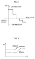
- the calculator 134 calculates a front vehicle wheel roll rigidity distribution ratio compensation amount, delta Kf, based upon a greater one of the target loads Ffra and Ffla according to a map such as shown in Fig. 4.
- the calculated compensation amount is inputted to an adder 136, wherein the compensation amount is added with a predetermined standard value Kfo of the front vehicle wheel roll rigidity distribution ratio to provide an output which is supplied to a comparison calculator 138.
- the calculator 138 judges whether or not the sum Kfo + delta Kf inputted from the adder 136 is between such a maximum value Kfmax and such a minimum value Kfmin of the front vehicle wheel roll rigidity distribution ratio as set out in a map shown in Fig. 5, and if the sum is between these maximum and minimum values, it outputs the value with no modification, whereas if the sum is larger than the maximum value or smaller than the minimum value, it outputs the maximum value or the minimum value, respectively.
- the output of the calculator 138 is supplied to the factor multiplier 108 to provide the front vehicle wheel roll rigidity distribution factor Kf, and is also supplied to a subtraction terminal of an adder 140 having an addition terminal supplied with 1, so that 1-Kf outputted from the adder 140 is supplied to the factor multiplier 116 to provide the rear vehicle wheel roll rigidity distribution ratio Kr.
- the target pressures for the working fluid chambers of the respective actuators for controlling the attitude of the vehicle body and the riding comfortableness of the vehicle according to the running conditions of the vehicle and the control electric currents supplied to the solenoids of the variable throttle means of the pressure control valves 22fr, 22fl, 22rr and 22rl to accomplish such target pressures may be calculated according to a feed forward control based upon the acceleration of the vehicle body, a feed back control based upon the vehicle height, etc..
- the roll rigidity distribution is shifted toward the rear vehicle wheels, so that the steering performance is shifted toward the oversteer, and therefore a good manoeuvrability is ensured
- the roll rigidity distribution is shifted toward the front vehicle wheels, so that the steering performance is shifted toward the understeer, and therefore a good stability of the vehicle is ensured.
- the load on the vehicle wheel at the outside of the turning is presumed from the sum of the target load, i.e. the feed forward control amount based upon the acceleration of the vehicle body and the static load on each vehicle wheel, it may be calculated from a multiplication of the pressure in the working fluid chamber of the actuator detected by a sensor and the pressure receiving area of the piston, or it may be presumed from a calculation based upon the transverse acceleration detected by the transverse acceleration sensor.
- the means to control the pressure in the working fluid chamber of each actuator is a pressure control valve, it may be a flow control valve.
- the roll rigidity distribution ratio is shifted toward rear vehicle wheels according to increase of the loads on the vehicle wheels at the outside of the turning.
Landscapes
- Engineering & Computer Science (AREA)
- Mechanical Engineering (AREA)
- Vehicle Body Suspensions (AREA)
Applications Claiming Priority (2)
| Application Number | Priority Date | Filing Date | Title |
|---|---|---|---|
| JP414873/90 | 1990-12-27 | ||
| JP2414873A JPH04231206A (ja) | 1990-12-27 | 1990-12-27 | 流体圧式アクティブサスペンション |
Publications (3)
| Publication Number | Publication Date |
|---|---|
| EP0492468A2 true EP0492468A2 (de) | 1992-07-01 |
| EP0492468A3 EP0492468A3 (en) | 1992-12-02 |
| EP0492468B1 EP0492468B1 (de) | 1995-08-23 |
Family
ID=18523304
Family Applications (1)
| Application Number | Title | Priority Date | Filing Date |
|---|---|---|---|
| EP91121854A Expired - Lifetime EP0492468B1 (de) | 1990-12-27 | 1991-12-19 | Aktive Aufhängung mit verändlichem Verteilungsverhältnis der Rollsteifigkeit |
Country Status (4)
| Country | Link |
|---|---|
| US (1) | US5253174A (de) |
| EP (1) | EP0492468B1 (de) |
| JP (1) | JPH04231206A (de) |
| DE (1) | DE69112366T2 (de) |
Cited By (1)
| Publication number | Priority date | Publication date | Assignee | Title |
|---|---|---|---|---|
| WO2003029036A1 (en) * | 2001-09-28 | 2003-04-10 | Kinetic Pty Limited | Vehicle suspension system |
Families Citing this family (16)
| Publication number | Priority date | Publication date | Assignee | Title |
|---|---|---|---|---|
| US6148252A (en) * | 1992-04-10 | 2000-11-14 | Unisia Jecs Corporation | Automotive suspension control system utilizing variable damping force shock absorber |
| JP3124629B2 (ja) * | 1992-07-14 | 2001-01-15 | ナルデック株式会社 | 車両のサスペンション装置 |
| DE4228893B4 (de) * | 1992-08-29 | 2004-04-08 | Robert Bosch Gmbh | System zur Beeinflussung der Fahrdynamik eines Kraftfahrzeugs |
| US5597180A (en) * | 1994-08-15 | 1997-01-28 | Ganzel; Blaise J. | Vehicle roll control apparatus |
| US5630623A (en) * | 1994-08-15 | 1997-05-20 | Kelsey Hayes | Vehicle roll control system |
| US5529324A (en) * | 1994-08-15 | 1996-06-25 | Kelsey-Hayes Company | System and method for vehicle roll control |
| US5794966A (en) * | 1996-02-05 | 1998-08-18 | Macleod; Kenneth J. | Vehicular suspension system |
| DE19753205C2 (de) * | 1997-12-01 | 2000-07-13 | Daimler Chrysler Ag | Regelbares Aufhängungssystem in einem aktiven Fahrwerk eines Kraftfahrzeugs |
| US7226056B2 (en) * | 2003-07-16 | 2007-06-05 | Kelsey-Hayes Company | Electro-magnetic vehicle roll control system |
| US7641208B1 (en) | 2003-07-16 | 2010-01-05 | Kelsey-Hayes Company | Vehicle roll control system with self-centering actuator |
| JP4333660B2 (ja) * | 2005-10-07 | 2009-09-16 | トヨタ自動車株式会社 | ロール角制御とロール剛性前後配分比制御を組み合わせた車輌 |
| DE102006017899A1 (de) * | 2006-04-13 | 2007-10-25 | Daimlerchrysler Ag | Verfahren und Vorrichtung zur Beeinflussung des Fahrverhaltens eines Fahrzeuges |
| US20070278028A1 (en) * | 2006-06-05 | 2007-12-06 | Wayne Robert Fought | Anti-aeration system for a suspension actuator |
| JP2010208619A (ja) * | 2009-02-10 | 2010-09-24 | Honda Motor Co Ltd | 車両挙動制御装置 |
| JP5572485B2 (ja) * | 2010-08-31 | 2014-08-13 | 日立オートモティブシステムズ株式会社 | サスペンション制御装置 |
| JP6579125B2 (ja) * | 2017-02-15 | 2019-09-25 | トヨタ自動車株式会社 | サスペンションシステム |
Citations (9)
| Publication number | Priority date | Publication date | Assignee | Title |
|---|---|---|---|---|
| EP0246655A1 (de) * | 1986-05-23 | 1987-11-25 | Nissan Motor Co., Ltd. | Kraftfahrzeug-Radaufhängung mit aktiver Steuerung und verbessertem Kurvenverhalten |
| JPS63145114A (ja) * | 1986-12-06 | 1988-06-17 | Mazda Motor Corp | 自動車のサスペンシヨン装置 |
| EP0285153A2 (de) * | 1987-03-31 | 1988-10-05 | Nissan Motor Co., Ltd. | Aktiv geregeltes Fahrzeugaufhängungssystem mit von der Beschleunigung und Winkelgeschwindigkeit abhängiger Antinick- und Antirollbewegungsvorrichtung |
| JPS641613A (en) * | 1987-06-23 | 1989-01-06 | Toyota Motor Corp | Active suspension for vehicle |
| EP0310094A2 (de) * | 1987-10-02 | 1989-04-05 | Nissan Motor Co., Ltd. | Integriertes Steuerungssystem für die Rollsteifigkeit und den Differentialschlupf |
| JPH0195927A (ja) * | 1987-10-09 | 1989-04-14 | Nissan Motor Co Ltd | 能動型サスペンション |
| JPH023511A (ja) * | 1988-06-10 | 1990-01-09 | Nissan Motor Co Ltd | 能動型サスペンション |
| JPH0238122A (ja) * | 1988-07-29 | 1990-02-07 | Nissan Motor Co Ltd | 能動型サスペンション装置 |
| JPH03139409A (ja) * | 1989-10-26 | 1991-06-13 | Mitsubishi Motors Corp | 車両用サスペンション装置 |
Family Cites Families (15)
| Publication number | Priority date | Publication date | Assignee | Title |
|---|---|---|---|---|
| JPS6181212A (ja) * | 1984-09-27 | 1986-04-24 | Mitsubishi Motors Corp | 電子制御サスペンシヨン装置 |
| JPS61193907A (ja) * | 1985-02-25 | 1986-08-28 | Nissan Motor Co Ltd | 能動型サスペンシヨン制御装置 |
| US4761022A (en) * | 1986-03-08 | 1988-08-02 | Toyota Jidosha Kabushiki Kaisha | Suspension controller for improved turning |
| JPH0780410B2 (ja) * | 1986-06-13 | 1995-08-30 | 日産自動車株式会社 | 車両用サスペンシヨン |
| EP0306004B1 (de) * | 1987-09-04 | 1992-07-15 | Toyota Jidosha Kabushiki Kaisha | Elektronisch geregeltes Fluidumaufhängungssystem |
| US4958850A (en) * | 1988-03-03 | 1990-09-25 | Toyota Jidosha Kabushiki Kaisha | Hydraulic circuit system for a vehicle height control device |
| DE68908521T2 (de) * | 1988-10-18 | 1994-03-31 | Nissan Motor | Aktive Radaufhängung für ein Kraftfahrzeug mit Driftwinkel-abhängiger Steuerung zur Verbesserung des Lenkverhaltens. |
| JPH02225119A (ja) * | 1988-11-10 | 1990-09-07 | Toyota Motor Corp | 流体圧式サスペンション |
| US4973080A (en) * | 1988-12-05 | 1990-11-27 | Toyota Jidosha Kabushiki Kaisha | Hydraulic suspension system for a vehicle with less abrupt change in vehicle height when started |
| JP2508830B2 (ja) * | 1988-12-28 | 1996-06-19 | トヨタ自動車株式会社 | 車輌のステア特性制御装置 |
| DE68921590T2 (de) * | 1988-12-28 | 1995-07-27 | Aisin Seiki | Aktives hydraulisches Steuersystem, welches das Steuern der Lage eines hochbelasteten Fahrzeugs ermöglicht. |
| US5071158A (en) * | 1989-08-28 | 1991-12-10 | Toyota Jidosha Kabushiki Kaisha | Fluid pressure type active suspension responsive to change of rate of change of vehicle height or change of acceleration of vehicle body |
| JP2594156B2 (ja) * | 1989-08-30 | 1997-03-26 | トヨタ自動車株式会社 | 流体圧式アクティブサスペンション |
| JPH0737205B2 (ja) * | 1989-09-05 | 1995-04-26 | トヨタ自動車株式会社 | 流体圧式アクティブサスペンション |
| US5104143A (en) * | 1989-09-27 | 1992-04-14 | Toyota Jidosha Kabushiki Kaisha | Vehicle suspension system with roll control variable according to vehicle speed |
-
1990
- 1990-12-27 JP JP2414873A patent/JPH04231206A/ja active Pending
-
1991
- 1991-12-11 US US07/804,755 patent/US5253174A/en not_active Expired - Fee Related
- 1991-12-19 EP EP91121854A patent/EP0492468B1/de not_active Expired - Lifetime
- 1991-12-19 DE DE69112366T patent/DE69112366T2/de not_active Expired - Fee Related
Patent Citations (9)
| Publication number | Priority date | Publication date | Assignee | Title |
|---|---|---|---|---|
| EP0246655A1 (de) * | 1986-05-23 | 1987-11-25 | Nissan Motor Co., Ltd. | Kraftfahrzeug-Radaufhängung mit aktiver Steuerung und verbessertem Kurvenverhalten |
| JPS63145114A (ja) * | 1986-12-06 | 1988-06-17 | Mazda Motor Corp | 自動車のサスペンシヨン装置 |
| EP0285153A2 (de) * | 1987-03-31 | 1988-10-05 | Nissan Motor Co., Ltd. | Aktiv geregeltes Fahrzeugaufhängungssystem mit von der Beschleunigung und Winkelgeschwindigkeit abhängiger Antinick- und Antirollbewegungsvorrichtung |
| JPS641613A (en) * | 1987-06-23 | 1989-01-06 | Toyota Motor Corp | Active suspension for vehicle |
| EP0310094A2 (de) * | 1987-10-02 | 1989-04-05 | Nissan Motor Co., Ltd. | Integriertes Steuerungssystem für die Rollsteifigkeit und den Differentialschlupf |
| JPH0195927A (ja) * | 1987-10-09 | 1989-04-14 | Nissan Motor Co Ltd | 能動型サスペンション |
| JPH023511A (ja) * | 1988-06-10 | 1990-01-09 | Nissan Motor Co Ltd | 能動型サスペンション |
| JPH0238122A (ja) * | 1988-07-29 | 1990-02-07 | Nissan Motor Co Ltd | 能動型サスペンション装置 |
| JPH03139409A (ja) * | 1989-10-26 | 1991-06-13 | Mitsubishi Motors Corp | 車両用サスペンション装置 |
Non-Patent Citations (6)
| Title |
|---|
| PATENT ABSTRACTS OF JAPAN vol. 12, no. 400 (M-756)1988 & JP-A-63 145 114 ( MAZDA MOTOR CO. ) * |
| PATENT ABSTRACTS OF JAPAN vol. 13, no. 163 (M-816)1989 & JP-A-64 001 613 ( TOYOTA MOTOR CORP. ) * |
| PATENT ABSTRACTS OF JAPAN vol. 13, no. 305 (M-849)1989 & JP-A-01 095 927 ( NISSAN MOTOR CO. ) * |
| PATENT ABSTRACTS OF JAPAN vol. 14, no. 132 (M-0948)13 March 1990 & JP-A-02 003 511 ( NISSAN MOTOR CO. ) * |
| PATENT ABSTRACTS OF JAPAN vol. 14, no. 196 (M-964)1990 & JP-A-02 038 122 ( NISSAN MOTOR CO. ) * |
| PATENT ABSTRACTS OF JAPAN vol. 15, no. 354 (M-1155)1991 & JP-A-03 139 409 ( MITSUBISHI MOTORS CORP. ) * |
Cited By (5)
| Publication number | Priority date | Publication date | Assignee | Title |
|---|---|---|---|---|
| WO2003029036A1 (en) * | 2001-09-28 | 2003-04-10 | Kinetic Pty Limited | Vehicle suspension system |
| EP1429930A1 (de) * | 2001-09-28 | 2004-06-23 | Kinetic Pty Limited | Fahrzeugaufhängungssystem |
| EP1429930A4 (de) * | 2001-09-28 | 2007-08-22 | Kinetic Pty Ltd | Fahrzeugaufhängungssystem |
| US7637513B2 (en) | 2001-09-28 | 2009-12-29 | Kinetic Pty. Limited | Vehicle suspension system |
| AU2008261186B2 (en) * | 2001-09-28 | 2010-11-18 | Kinetic Pty Ltd. | Vehicle Suspension System |
Also Published As
| Publication number | Publication date |
|---|---|
| DE69112366D1 (de) | 1995-09-28 |
| EP0492468A3 (en) | 1992-12-02 |
| DE69112366T2 (de) | 1996-02-01 |
| JPH04231206A (ja) | 1992-08-20 |
| EP0492468B1 (de) | 1995-08-23 |
| US5253174A (en) | 1993-10-12 |
Similar Documents
| Publication | Publication Date | Title |
|---|---|---|
| US5253174A (en) | Active suspension with variable roll rigidity distribution ratio | |
| US5384705A (en) | Active suspension with roll control by reducibly modified estimated transverse acceleration | |
| EP0556055B1 (de) | Aufhängungssystem für ein Kraftfahrzeug | |
| JP2503277B2 (ja) | サスペンション制御装置 | |
| JPS62198509A (ja) | 車輌用車高調整式ロ−ル制御装置 | |
| JP2623853B2 (ja) | 能動型サスペンション | |
| EP0420285A2 (de) | Aktivaufhängungssystem für Kraftfahrzeug | |
| JP2551787B2 (ja) | 減衰力可変式サスペンション制御装置 | |
| US5257814A (en) | Suspension controller | |
| JP2874427B2 (ja) | 車両用アクティブサスペンション装置 | |
| US20030060960A1 (en) | Method and device for situation-dependent and driver-dependent attenuation of ESP stabilization measures | |
| JPH04224412A (ja) | 流体圧式アクティブサスペンション | |
| JPH02296513A (ja) | 能動型サスペンション | |
| JPH04328010A (ja) | 流体圧式アクティブサスペンション | |
| JPH0516633A (ja) | 車両用アクテイブサスペンシヨン | |
| JP2874425B2 (ja) | 車両用アクティブサスペンション装置 | |
| JP2773289B2 (ja) | 能動型サスペンション | |
| JPH04231207A (ja) | 流体圧式アクティブサスペンション | |
| JPH04231205A (ja) | 能動型サスペンション | |
| JP3057852B2 (ja) | サスペンション装置 | |
| JP2889280B2 (ja) | 車両のサスペンション装置 | |
| JP2623815B2 (ja) | 流体圧式サスペンションの作動流体供給装置 | |
| JP2699642B2 (ja) | 能動型サスペンション | |
| JPH06206416A (ja) | 流体圧式アクティブサスペンション | |
| JP3071221B2 (ja) | 流体圧式アクティブサスペンション |
Legal Events
| Date | Code | Title | Description |
|---|---|---|---|
| PUAI | Public reference made under article 153(3) epc to a published international application that has entered the european phase |
Free format text: ORIGINAL CODE: 0009012 |
|
| AK | Designated contracting states |
Kind code of ref document: A2 Designated state(s): DE FR GB |
|
| PUAL | Search report despatched |
Free format text: ORIGINAL CODE: 0009013 |
|
| AK | Designated contracting states |
Kind code of ref document: A3 Designated state(s): DE FR GB |
|
| 17P | Request for examination filed |
Effective date: 19930119 |
|
| 17Q | First examination report despatched |
Effective date: 19940316 |
|
| GRAA | (expected) grant |
Free format text: ORIGINAL CODE: 0009210 |
|
| AK | Designated contracting states |
Kind code of ref document: B1 Designated state(s): DE FR GB |
|
| ET | Fr: translation filed | ||
| REF | Corresponds to: |
Ref document number: 69112366 Country of ref document: DE Date of ref document: 19950928 |
|
| PLBE | No opposition filed within time limit |
Free format text: ORIGINAL CODE: 0009261 |
|
| STAA | Information on the status of an ep patent application or granted ep patent |
Free format text: STATUS: NO OPPOSITION FILED WITHIN TIME LIMIT |
|
| 26N | No opposition filed | ||
| PGFP | Annual fee paid to national office [announced via postgrant information from national office to epo] |
Ref country code: FR Payment date: 19981209 Year of fee payment: 8 |
|
| PGFP | Annual fee paid to national office [announced via postgrant information from national office to epo] |
Ref country code: GB Payment date: 19981224 Year of fee payment: 8 |
|
| PGFP | Annual fee paid to national office [announced via postgrant information from national office to epo] |
Ref country code: DE Payment date: 19981229 Year of fee payment: 8 |
|
| PG25 | Lapsed in a contracting state [announced via postgrant information from national office to epo] |
Ref country code: GB Free format text: LAPSE BECAUSE OF NON-PAYMENT OF DUE FEES Effective date: 19991219 |
|
| GBPC | Gb: european patent ceased through non-payment of renewal fee |
Effective date: 19991219 |
|
| PG25 | Lapsed in a contracting state [announced via postgrant information from national office to epo] |
Ref country code: FR Free format text: LAPSE BECAUSE OF NON-PAYMENT OF DUE FEES Effective date: 20000831 |
|
| PG25 | Lapsed in a contracting state [announced via postgrant information from national office to epo] |
Ref country code: DE Free format text: LAPSE BECAUSE OF NON-PAYMENT OF DUE FEES Effective date: 20001003 |
|
| REG | Reference to a national code |
Ref country code: FR Ref legal event code: ST |