EP0492175B1 - Ferme-porte - Google Patents
Ferme-porte Download PDFInfo
- Publication number
- EP0492175B1 EP0492175B1 EP91120383A EP91120383A EP0492175B1 EP 0492175 B1 EP0492175 B1 EP 0492175B1 EP 91120383 A EP91120383 A EP 91120383A EP 91120383 A EP91120383 A EP 91120383A EP 0492175 B1 EP0492175 B1 EP 0492175B1
- Authority
- EP
- European Patent Office
- Prior art keywords
- damping piston
- spring support
- door closer
- closer
- support member
- Prior art date
- Legal status (The legal status is an assumption and is not a legal conclusion. Google has not performed a legal analysis and makes no representation as to the accuracy of the status listed.)
- Expired - Lifetime
Links
- 238000013016 damping Methods 0.000 claims abstract description 35
- 230000002265 prevention Effects 0.000 abstract 1
- 230000005540 biological transmission Effects 0.000 description 6
- 238000007789 sealing Methods 0.000 description 2
- 238000000418 atomic force spectrum Methods 0.000 description 1
- 230000006835 compression Effects 0.000 description 1
- 238000007906 compression Methods 0.000 description 1
- 210000003746 feather Anatomy 0.000 description 1
- 230000001771 impaired effect Effects 0.000 description 1
- 238000004519 manufacturing process Methods 0.000 description 1
Images

Classifications
-
- E—FIXED CONSTRUCTIONS
- E05—LOCKS; KEYS; WINDOW OR DOOR FITTINGS; SAFES
- E05F—DEVICES FOR MOVING WINGS INTO OPEN OR CLOSED POSITION; CHECKS FOR WINGS; WING FITTINGS NOT OTHERWISE PROVIDED FOR, CONCERNED WITH THE FUNCTIONING OF THE WING
- E05F3/00—Closers or openers with braking devices, e.g. checks; Construction of pneumatic or liquid braking devices
- E05F3/04—Closers or openers with braking devices, e.g. checks; Construction of pneumatic or liquid braking devices with liquid piston brakes
- E05F3/10—Closers or openers with braking devices, e.g. checks; Construction of pneumatic or liquid braking devices with liquid piston brakes with a spring, other than a torsion spring, and a piston, the axes of which are the same or lie in the same direction
- E05F3/104—Closers or openers with braking devices, e.g. checks; Construction of pneumatic or liquid braking devices with liquid piston brakes with a spring, other than a torsion spring, and a piston, the axes of which are the same or lie in the same direction with cam-and-slide transmission between driving shaft and piston within the closer housing
-
- E—FIXED CONSTRUCTIONS
- E05—LOCKS; KEYS; WINDOW OR DOOR FITTINGS; SAFES
- E05F—DEVICES FOR MOVING WINGS INTO OPEN OR CLOSED POSITION; CHECKS FOR WINGS; WING FITTINGS NOT OTHERWISE PROVIDED FOR, CONCERNED WITH THE FUNCTIONING OF THE WING
- E05F3/00—Closers or openers with braking devices, e.g. checks; Construction of pneumatic or liquid braking devices
- E05F3/22—Additional arrangements for closers, e.g. for holding the wing in opened or other position
- E05F3/225—Additional arrangements for closers, e.g. for holding the wing in opened or other position mounted at the bottom of wings, e.g. details related to seals, covers, connections to the wings, embedding in the floor
-
- E—FIXED CONSTRUCTIONS
- E05—LOCKS; KEYS; WINDOW OR DOOR FITTINGS; SAFES
- E05Y—INDEXING SCHEME ASSOCIATED WITH SUBCLASSES E05D AND E05F, RELATING TO CONSTRUCTION ELEMENTS, ELECTRIC CONTROL, POWER SUPPLY, POWER SIGNAL OR TRANSMISSION, USER INTERFACES, MOUNTING OR COUPLING, DETAILS, ACCESSORIES, AUXILIARY OPERATIONS NOT OTHERWISE PROVIDED FOR, APPLICATION THEREOF
- E05Y2600/00—Mounting or coupling arrangements for elements provided for in this subclass
- E05Y2600/60—Mounting or coupling members; Accessories therefor
- E05Y2600/634—Spacers
-
- E—FIXED CONSTRUCTIONS
- E05—LOCKS; KEYS; WINDOW OR DOOR FITTINGS; SAFES
- E05Y—INDEXING SCHEME ASSOCIATED WITH SUBCLASSES E05D AND E05F, RELATING TO CONSTRUCTION ELEMENTS, ELECTRIC CONTROL, POWER SUPPLY, POWER SIGNAL OR TRANSMISSION, USER INTERFACES, MOUNTING OR COUPLING, DETAILS, ACCESSORIES, AUXILIARY OPERATIONS NOT OTHERWISE PROVIDED FOR, APPLICATION THEREOF
- E05Y2900/00—Application of doors, windows, wings or fittings thereof
- E05Y2900/10—Application of doors, windows, wings or fittings thereof for buildings or parts thereof
- E05Y2900/13—Type of wing
- E05Y2900/132—Doors
Definitions
- the invention relates to a door closer according to the preamble of claim 1.
- Such a closer is known from DE-OS 33 45 004.
- predetermined strokes adapted to the opening and closing characteristics are assigned by the design of the cam tracks, the spring support member and also the damping piston depending on the door opening angle or angle of rotation.
- the cam track assigned to the fader support member permits a stroke assigned to the angle of rotation of the closer shaft.
- DE-OS 20 41 099 shows a floor door closer in which the sliding member of a second damping device is secured against rotation. This protection against rotation is realized by a stop protruding into a groove. As a result, the sliding member cannot twist during an axial movement.
- the object of the invention is to provide a door closer of the type mentioned, in which a rotation of the damping piston and the force transmission member about the longitudinal axis with respect to the cam disc is avoided, ie they must be able to move independently of one another in the axial movement. Likewise, the anti-rotation device must not have any influence on the cam disc used.
- securing means are present which prevent the damping piston and the spring support member from rotating against one another.
- the function of the door closer is in no way impaired by the attachment of the securing means.
- Two rods are used as securing means, which are advantageous on the one hand e.g. are firmly anchored in the spring support member and, on the other hand, can smoothly plunge into blind bores on the opposite side within the damping piston.
- the securing rods are arranged on each side of the closer shaft in the axial direction of the housing. This makes it possible that the locking rods are supported either on one or the other side of the closer shaft when the damping piston or the spring support member is rotated.
- a round bar can be positively and positively e.g. anchor within the spring support member or the damping piston. On the opposite side there are free bores in which these round bars can dip without friction when the door closer is actuated.
- the locking pins thus represent a rotation lock of the pistons with respect to the cam disc. This always ensures that the piston or the spring support member remain in their original position. If the spring support member or the damping piston are brought out of their original position, the rollers can no longer come into engagement with the cam disc properly. There is a pushing and rubbing, which results in increased wear of the door closer. Also, the degree of damping of the door closer is no longer correct when the damping piston or the spring support member is turned, because other forces are used within the door closer. When the spring support member is rotated, the force curve from the spring via the roller to the cam disc is significantly worse, and the required closing torques are no longer provided, which may not ensure that the door is closed securely.
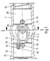
- the section (1) of the door closer shown in FIG. 1 has been shown in section.
- the closer shaft (2) is located inside the housing (1).
- the cam disc (3) is non-positively and positively connected to the closer shaft.
- Both the roller (13) and the force transmission roller (14) are in contact with the cam disc (3) via spring forces that lie behind the damping piston (10) and the spring support member (20).
- the roller (13) is located within the damping piston (10) and is rotatably supported in the damping piston (10) by an axle bolt (11).
- the power transmission roller (14) is also rotatably mounted within the spring support member (20) by means of an axle bolt (12).
- a force is transmitted against the spring support member (20) via the pressure spring (15) via the force transmission roller (14) to the cam disc (3).
- a spring (21) is also located behind the damping piston (10).
- two securing rods (8) are located within the spring support member (20). These locking bars run in the longitudinal axis of the closer housing and transverse to the closer shaft (2). They are firmly connected to the spring support member (20) via a non-positive and positive connection (18). This can happen, for example, in that heavy-duty locking pins are provided as securing rods (8), which sit with a press fit in the spring support member (20). It would also be possible to press them into the damping piston (10). It is crucial for the function of the safety rods (8) that they close to the closer shaft (2) To have position. They therefore run with appropriate play directly above the cam disc curve (3) and directly past the two sides of the longitudinal axis of the closer shaft (2).
- the closer shaft extension (9) is required to support the deep groove ball bearing located in the sealing plug (6), but not shown. In the area of the security rods (8), this shaft extension is interrupted by a groove to make room for the security rods (8). This measure ensures that the spring support member (20) cannot rotate with respect to the cam disc (3). The spring support member (20) would not change its position in relation to the cam disc (3) by either a right or a left turn.
- the locking rods (8) are made long enough so that they can be immersed smoothly with a clearance fit within the damping piston (10) in two blind holes (16).
- the depth and length of the blind bores (16) are dimensioned such that a sufficiently large free space (17) remains between the inserted safety rod end (19) and the end of the blind bore (16).
- This free space (17) must be dimensioned so deep that during the longitudinal movements of the damping piston (10) and the spring support member (20) the safety rods (8) do not stop (10) within the damping piston.
- the aforementioned blind bore (16) can also be present within the spring support member (20). It is important that at least two rods are used, because if only one rod were used, the damping piston (10) and the spring support member (20) might only be secured against one direction of rotation.
- round materials have been used as securing rods (8). These round bars or pins represent an inexpensive fuse and are also easy to handle when manufacturing the door closer. Square materials or other materials can of course also be used just as well.
Landscapes
- Closing And Opening Devices For Wings, And Checks For Wings (AREA)
- Refrigerator Housings (AREA)
- Vibration Dampers (AREA)
- Medicines Containing Material From Animals Or Micro-Organisms (AREA)
- Compounds Of Unknown Constitution (AREA)
Claims (5)
- Ferme-porte comportant un axe pouvant être actionné dans le sens de la fermeture par un dispositif de ressort (2) et un piston amortisseur (10) en liaison fonctionelle avec l'axe, ainsi qu'un bras de commande accouplé à l'axe en dehors du boîtier (1) et pouvant pivoter, ainsi qu'un disque de came de levage (3) relié par interpénétration par la force à l'axe du ferme-porte à l'intérieur du boîtier (1), came dont la piste incurvée correspondant au sens d'ouverture est mis en contact par un élément d'appui à ressort sur au moins un galet (14) et dont la piste incurvée correspondant au sens de fermeture est mis en contact par un piston amortisseur (10) sur un autre galet (13), ferme-porte caractérisé- en ce que l'élément d'appui à ressort (20) et le piston amortisseur (10) sont placés sans pivotement possible en face du disque de cam de levage (3),
et- en ce que la sécurité anti-pivotement est constituée d'au moins deux tiges (8) s'étendant dans le sens de l'axe du boîtier et transversalement au sens de l'axe du ferme-porte (2), au moins une tige (8) se situant de chaque côté de l'axe du ferme-porte. - Ferme-porte selon la revendication 1, caractérisé
- en ce que les tiges de sécurité (8) sont engagées dans une liaison (18) par interpénétration par la forme et par la force avec l'élément de support de ressort (20) et peuvent être enfoncées dans le piston amortisseur (10) dans un perçage libre (perçage borgne 16) sans frottement. - Ferme-porte selon la revendication 1, caractérisé
- en ce que les tiges de sécurité (8) sont engagées dans une liaison (18) par interpénétration par la forme et par la force avec le piston amortisseur (10) et peuvent être enfoncées dans l'élément de support de ressort (20) dans un alésage libre (alésage borgne 16) sans frottement. - Ferme-porte selon les revendications 1 a 3, caractérisé
- en ce que les tiges de sécurité (8) sont constituées d'un matériau rond. - Ferme-porte selon les revendications 1 a 4, caractérisé
- en ce que les tiges de sécurité (8) sont réalisées en broches de serrage massives ou en douilles des serrage.
Priority Applications (1)
| Application Number | Priority Date | Filing Date | Title |
|---|---|---|---|
| AT91120383T ATE90137T1 (de) | 1990-12-24 | 1991-11-28 | Tuerschliesser. |
Applications Claiming Priority (2)
| Application Number | Priority Date | Filing Date | Title |
|---|---|---|---|
| DE4041824A DE4041824C1 (fr) | 1990-12-24 | 1990-12-24 | |
| DE4041824 | 1990-12-24 |
Publications (2)
| Publication Number | Publication Date |
|---|---|
| EP0492175A1 EP0492175A1 (fr) | 1992-07-01 |
| EP0492175B1 true EP0492175B1 (fr) | 1993-06-02 |
Family
ID=6421471
Family Applications (1)
| Application Number | Title | Priority Date | Filing Date |
|---|---|---|---|
| EP91120383A Expired - Lifetime EP0492175B1 (fr) | 1990-12-24 | 1991-11-28 | Ferme-porte |
Country Status (4)
| Country | Link |
|---|---|
| EP (1) | EP0492175B1 (fr) |
| AT (1) | ATE90137T1 (fr) |
| DE (2) | DE4041824C1 (fr) |
| ES (1) | ES2032728T3 (fr) |
Families Citing this family (8)
| Publication number | Priority date | Publication date | Assignee | Title |
|---|---|---|---|---|
| DE9209276U1 (fr) * | 1992-07-10 | 1992-08-27 | Dorma Gmbh + Co. Kg, 5828 Ennepetal, De | |
| DE19603186C2 (de) * | 1996-01-30 | 1998-02-19 | Dorma Gmbh & Co Kg | Obentürschließer |
| DE19922916A1 (de) * | 1999-01-18 | 2000-07-20 | Geze Gmbh | Türschließer |
| DE102004041358B4 (de) * | 2004-08-25 | 2006-07-13 | Dorma Gmbh + Co. Kg | Obentürschließer |
| DE102004061627B4 (de) * | 2004-12-17 | 2007-02-01 | Dorma Gmbh + Co. Kg | Türschließer |
| DE102004061624C5 (de) | 2004-12-17 | 2011-02-03 | Dorma Gmbh + Co. Kg | Türantrieb, insbesondere Drehtürantieb |
| CN101135216B (zh) * | 2006-09-01 | 2012-12-12 | 多玛两合有限公司 | 上部闭门器 |
| ES2865059T3 (es) * | 2019-01-16 | 2021-10-14 | Dormakaba Deutschland Gmbh | Accionador de puerta |
Family Cites Families (4)
| Publication number | Priority date | Publication date | Assignee | Title |
|---|---|---|---|---|
| GB745271A (en) * | 1953-10-02 | 1956-02-22 | Newman William & Sons Ltd | Improvements relating to spring door-closing appliances |
| DE2041099A1 (de) * | 1970-08-19 | 1972-02-24 | Ver Baubeschlag Gretsch Co | Tuerschliesser,insbesondere Bodentuerschliesser |
| GB1344945A (en) * | 1972-01-06 | 1974-01-23 | Gibbons Ld James | Doorclosing mechanism |
| DE3345004A1 (de) * | 1983-12-13 | 1985-06-13 | Dorma-Baubeschlag Gmbh & Co Kg, 5828 Ennepetal | Obentuerschliesser |
-
1990
- 1990-12-24 DE DE4041824A patent/DE4041824C1/de not_active Expired - Fee Related
-
1991
- 1991-11-28 DE DE9191120383T patent/DE59100134D1/de not_active Expired - Lifetime
- 1991-11-28 EP EP91120383A patent/EP0492175B1/fr not_active Expired - Lifetime
- 1991-11-28 AT AT91120383T patent/ATE90137T1/de not_active IP Right Cessation
- 1991-11-28 ES ES199191120383T patent/ES2032728T3/es not_active Expired - Lifetime
Also Published As
| Publication number | Publication date |
|---|---|
| DE59100134D1 (en) | 1993-07-08 |
| ATE90137T1 (de) | 1993-06-15 |
| DE4041824C1 (fr) | 1992-06-11 |
| ES2032728T1 (es) | 1993-03-01 |
| EP0492175A1 (fr) | 1992-07-01 |
| ES2032728T3 (es) | 1993-12-01 |
Similar Documents
| Publication | Publication Date | Title |
|---|---|---|
| DE19506220C2 (de) | Türschließer | |
| DE4038720C2 (de) | Obertürschließer mit Gleitschienengestänge | |
| DE19922916A1 (de) | Türschließer | |
| DE19506355C2 (de) | Selbsttätiger Türschließer | |
| EP0492175B1 (fr) | Ferme-porte | |
| DE2821766C3 (de) | Absperrklappe | |
| DE3425909A1 (de) | Federueberwachungsgeraet | |
| EP1239496B1 (fr) | Charnière avec interrupteur | |
| EP0597170B1 (fr) | Serrure à verrou tournant | |
| EP0830491B1 (fr) | Systeme de fermeture de porte par le haut | |
| DE3844627A1 (de) | Mit verschlussmitteln ausgeruestetes fenster, tuer oder dergleichen | |
| DE10031403C2 (de) | Obentürschließer mit einer Gleitschienenanordnung | |
| EP1431497A2 (fr) | Dispositif désembrayable d'un entraínement d'une aile de porte ou de fenêtre | |
| DE1915751C3 (de) | Schwenklagerung für Türhaltebänder von Türfeststellern für Kraftwagentüren | |
| EP3344881B1 (fr) | Vérin de blocage hydromécanique et système de commande hydraulique pour l'actionner | |
| EP2818618B1 (fr) | Dispositif de régulation de la séquence de fermeture d'une installation de porte rotative à deux battants | |
| DE102006002751A1 (de) | Drehflügeltürantrieb mit Kurvenscheibe | |
| WO2020169309A1 (fr) | Entraînement à vis à billes avec sécurité antirotation | |
| DE3228933A1 (de) | Drehzapfenlager fuer tueren, insbesondere fuer pendeltueren | |
| DE3823718A1 (de) | Vorrichtung zum begrenzen und justieren des schaltweges bei armaturen | |
| EP0861953A1 (fr) | Poignée de manoeuvre | |
| DE19532262A1 (de) | Vorrichtung zur Schließfolgeregelung für zweiflügelige Türen | |
| DE102008044772B3 (de) | Dreh-Absperrventil mit Leckagesicherung | |
| DE3901936C2 (de) | Drehstangenverschluß | |
| DE3538883C2 (fr) |
Legal Events
| Date | Code | Title | Description |
|---|---|---|---|
| PUAI | Public reference made under article 153(3) epc to a published international application that has entered the european phase |
Free format text: ORIGINAL CODE: 0009012 |
|
| ITCL | It: translation for ep claims filed |
Representative=s name: DE DOMINICIS & MAYER S.R.L. |
|
| 17P | Request for examination filed |
Effective date: 19920401 |
|
| AK | Designated contracting states |
Kind code of ref document: A1 Designated state(s): AT BE CH DE ES FR GB IT LI NL |
|
| GBC | Gb: translation of claims filed (gb section 78(7)/1977) | ||
| TCNL | Nl: translation of patent claims filed | ||
| EL | Fr: translation of claims filed | ||
| 17Q | First examination report despatched |
Effective date: 19921027 |
|
| ITF | It: translation for a ep patent filed |
Owner name: DE DOMINICIS & MAYER S.R.L. |
|
| GRAA | (expected) grant |
Free format text: ORIGINAL CODE: 0009210 |
|
| STAA | Information on the status of an ep patent application or granted ep patent |
Free format text: STATUS: THE PATENT HAS BEEN GRANTED |
|
| AK | Designated contracting states |
Kind code of ref document: B1 Designated state(s): AT BE CH DE ES FR GB IT LI NL |
|
| REF | Corresponds to: |
Ref document number: 90137 Country of ref document: AT Date of ref document: 19930615 Kind code of ref document: T |
|
| ET | Fr: translation filed | ||
| GBT | Gb: translation of ep patent filed (gb section 77(6)(a)/1977) |
Effective date: 19930609 |
|
| REF | Corresponds to: |
Ref document number: 59100134 Country of ref document: DE Date of ref document: 19930708 |
|
| ET1 | Fr: translation filed ** revision of the translation of the patent or the claims | ||
| REG | Reference to a national code |
Ref country code: ES Ref legal event code: FG2A Ref document number: 2032728 Country of ref document: ES Kind code of ref document: T3 |
|
| PLBE | No opposition filed within time limit |
Free format text: ORIGINAL CODE: 0009261 |
|
| 26N | No opposition filed | ||
| EL | Fr: translation of claims filed |
Free format text: BO 23/93 DU 930611 LA MENTION DE LA REMISE DE LA TRADUCTION DU BOPI 93/23 EST A CONSIDERER COMME NULLE ET NON AVENUE BO 27/93 DU 930709 LA MENTION DE LA REMISE DE LA TRADUCTION REVISEE DU BOPI 93/27 EST A CONSIDERER COMME TRADUCTION REMISE |
|
| REG | Reference to a national code |
Ref country code: GB Ref legal event code: IF02 |
|
| PG25 | Lapsed in a contracting state [announced via postgrant information from national office to epo] |
Ref country code: IT Free format text: LAPSE BECAUSE OF NON-PAYMENT OF DUE FEES;WARNING: LAPSES OF ITALIAN PATENTS WITH EFFECTIVE DATE BEFORE 2007 MAY HAVE OCCURRED AT ANY TIME BEFORE 2007. THE CORRECT EFFECTIVE DATE MAY BE DIFFERENT FROM THE ONE RECORDED. Effective date: 20051128 |
|
| REG | Reference to a national code |
Ref country code: CH Ref legal event code: PCOW Free format text: DORMA GMBH + CO. KG;DORMA PLATZ 1;58256 ENNEPETAL (DE) |
|
| PGFP | Annual fee paid to national office [announced via postgrant information from national office to epo] |
Ref country code: FR Payment date: 20101130 Year of fee payment: 20 Ref country code: NL Payment date: 20101111 Year of fee payment: 20 Ref country code: AT Payment date: 20101112 Year of fee payment: 20 |
|
| PGFP | Annual fee paid to national office [announced via postgrant information from national office to epo] |
Ref country code: CH Payment date: 20101123 Year of fee payment: 20 Ref country code: DE Payment date: 20101119 Year of fee payment: 20 |
|
| REG | Reference to a national code |
Ref country code: CH Ref legal event code: PFA Owner name: DORMA GMBH + CO. KG Free format text: DORMA GMBH + CO. KG#DORMA PLATZ 1#58256 ENNEPETAL (DE) -TRANSFER TO- DORMA GMBH + CO. KG#DORMA PLATZ 1#58256 ENNEPETAL (DE) |
|
| PGFP | Annual fee paid to national office [announced via postgrant information from national office to epo] |
Ref country code: GB Payment date: 20101118 Year of fee payment: 20 Ref country code: BE Payment date: 20101117 Year of fee payment: 20 |
|
| PGFP | Annual fee paid to national office [announced via postgrant information from national office to epo] |
Ref country code: ES Payment date: 20101124 Year of fee payment: 20 |
|
| REG | Reference to a national code |
Ref country code: DE Ref legal event code: R071 Ref document number: 59100134 Country of ref document: DE |
|
| REG | Reference to a national code |
Ref country code: DE Ref legal event code: R071 Ref document number: 59100134 Country of ref document: DE |
|
| BE20 | Be: patent expired |
Owner name: *DORMA G.M.B.H. + CO. K.G. Effective date: 20111128 |
|
| REG | Reference to a national code |
Ref country code: NL Ref legal event code: V4 Effective date: 20111128 |
|
| REG | Reference to a national code |
Ref country code: CH Ref legal event code: PL |
|
| REG | Reference to a national code |
Ref country code: GB Ref legal event code: PE20 Expiry date: 20111127 |
|
| PG25 | Lapsed in a contracting state [announced via postgrant information from national office to epo] |
Ref country code: NL Free format text: LAPSE BECAUSE OF EXPIRATION OF PROTECTION Effective date: 20111128 |
|
| REG | Reference to a national code |
Ref country code: AT Ref legal event code: MK07 Ref document number: 90137 Country of ref document: AT Kind code of ref document: T Effective date: 20111128 |
|
| PG25 | Lapsed in a contracting state [announced via postgrant information from national office to epo] |
Ref country code: GB Free format text: LAPSE BECAUSE OF EXPIRATION OF PROTECTION Effective date: 20111127 |
|
| PG25 | Lapsed in a contracting state [announced via postgrant information from national office to epo] |
Ref country code: DE Free format text: LAPSE BECAUSE OF EXPIRATION OF PROTECTION Effective date: 20111129 |
|
| REG | Reference to a national code |
Ref country code: ES Ref legal event code: FD2A Effective date: 20130802 |
|
| PG25 | Lapsed in a contracting state [announced via postgrant information from national office to epo] |
Ref country code: ES Free format text: LAPSE BECAUSE OF EXPIRATION OF PROTECTION Effective date: 20111129 |