EP0492175B1 - Door closer - Google Patents
Door closer Download PDFInfo
- Publication number
- EP0492175B1 EP0492175B1 EP91120383A EP91120383A EP0492175B1 EP 0492175 B1 EP0492175 B1 EP 0492175B1 EP 91120383 A EP91120383 A EP 91120383A EP 91120383 A EP91120383 A EP 91120383A EP 0492175 B1 EP0492175 B1 EP 0492175B1
- Authority
- EP
- European Patent Office
- Prior art keywords
- damping piston
- spring support
- door closer
- closer
- support member
- Prior art date
- Legal status (The legal status is an assumption and is not a legal conclusion. Google has not performed a legal analysis and makes no representation as to the accuracy of the status listed.)
- Expired - Lifetime
Links
Images

Classifications
-
- E—FIXED CONSTRUCTIONS
- E05—LOCKS; KEYS; WINDOW OR DOOR FITTINGS; SAFES
- E05F—DEVICES FOR MOVING WINGS INTO OPEN OR CLOSED POSITION; CHECKS FOR WINGS; WING FITTINGS NOT OTHERWISE PROVIDED FOR, CONCERNED WITH THE FUNCTIONING OF THE WING
- E05F3/00—Closers or openers with braking devices, e.g. checks; Construction of pneumatic or liquid braking devices
- E05F3/04—Closers or openers with braking devices, e.g. checks; Construction of pneumatic or liquid braking devices with liquid piston brakes
- E05F3/10—Closers or openers with braking devices, e.g. checks; Construction of pneumatic or liquid braking devices with liquid piston brakes with a spring, other than a torsion spring, and a piston, the axes of which are the same or lie in the same direction
- E05F3/104—Closers or openers with braking devices, e.g. checks; Construction of pneumatic or liquid braking devices with liquid piston brakes with a spring, other than a torsion spring, and a piston, the axes of which are the same or lie in the same direction with cam-and-slide transmission between driving shaft and piston within the closer housing
-
- E—FIXED CONSTRUCTIONS
- E05—LOCKS; KEYS; WINDOW OR DOOR FITTINGS; SAFES
- E05F—DEVICES FOR MOVING WINGS INTO OPEN OR CLOSED POSITION; CHECKS FOR WINGS; WING FITTINGS NOT OTHERWISE PROVIDED FOR, CONCERNED WITH THE FUNCTIONING OF THE WING
- E05F3/00—Closers or openers with braking devices, e.g. checks; Construction of pneumatic or liquid braking devices
- E05F3/22—Additional arrangements for closers, e.g. for holding the wing in opened or other position
- E05F3/225—Additional arrangements for closers, e.g. for holding the wing in opened or other position mounted at the bottom of wings, e.g. details related to seals, covers, connections to the wings, embedding in the floor
-
- E—FIXED CONSTRUCTIONS
- E05—LOCKS; KEYS; WINDOW OR DOOR FITTINGS; SAFES
- E05Y—INDEXING SCHEME RELATING TO HINGES OR OTHER SUSPENSION DEVICES FOR DOORS, WINDOWS OR WINGS AND DEVICES FOR MOVING WINGS INTO OPEN OR CLOSED POSITION, CHECKS FOR WINGS AND WING FITTINGS NOT OTHERWISE PROVIDED FOR, CONCERNED WITH THE FUNCTIONING OF THE WING
- E05Y2600/00—Mounting or coupling arrangements for elements provided for in this subclass
- E05Y2600/60—Mounting or coupling members; Accessories therefore
- E05Y2600/634—Spacers
-
- E—FIXED CONSTRUCTIONS
- E05—LOCKS; KEYS; WINDOW OR DOOR FITTINGS; SAFES
- E05Y—INDEXING SCHEME RELATING TO HINGES OR OTHER SUSPENSION DEVICES FOR DOORS, WINDOWS OR WINGS AND DEVICES FOR MOVING WINGS INTO OPEN OR CLOSED POSITION, CHECKS FOR WINGS AND WING FITTINGS NOT OTHERWISE PROVIDED FOR, CONCERNED WITH THE FUNCTIONING OF THE WING
- E05Y2900/00—Application of doors, windows, wings or fittings thereof
- E05Y2900/10—Application of doors, windows, wings or fittings thereof for buildings or parts thereof
- E05Y2900/13—Application of doors, windows, wings or fittings thereof for buildings or parts thereof characterised by the type of wing
- E05Y2900/132—Doors
Definitions
- the invention relates to a door closer according to the preamble of claim 1.
- Such a closer is known from DE-OS 33 45 004.
- predetermined strokes adapted to the opening and closing characteristics are assigned by the design of the cam tracks, the spring support member and also the damping piston depending on the door opening angle or angle of rotation.
- the cam track assigned to the fader support member permits a stroke assigned to the angle of rotation of the closer shaft.
- DE-OS 20 41 099 shows a floor door closer in which the sliding member of a second damping device is secured against rotation. This protection against rotation is realized by a stop protruding into a groove. As a result, the sliding member cannot twist during an axial movement.
- the object of the invention is to provide a door closer of the type mentioned, in which a rotation of the damping piston and the force transmission member about the longitudinal axis with respect to the cam disc is avoided, ie they must be able to move independently of one another in the axial movement. Likewise, the anti-rotation device must not have any influence on the cam disc used.
- securing means are present which prevent the damping piston and the spring support member from rotating against one another.
- the function of the door closer is in no way impaired by the attachment of the securing means.
- Two rods are used as securing means, which are advantageous on the one hand e.g. are firmly anchored in the spring support member and, on the other hand, can smoothly plunge into blind bores on the opposite side within the damping piston.
- the securing rods are arranged on each side of the closer shaft in the axial direction of the housing. This makes it possible that the locking rods are supported either on one or the other side of the closer shaft when the damping piston or the spring support member is rotated.
- a round bar can be positively and positively e.g. anchor within the spring support member or the damping piston. On the opposite side there are free bores in which these round bars can dip without friction when the door closer is actuated.
- the locking pins thus represent a rotation lock of the pistons with respect to the cam disc. This always ensures that the piston or the spring support member remain in their original position. If the spring support member or the damping piston are brought out of their original position, the rollers can no longer come into engagement with the cam disc properly. There is a pushing and rubbing, which results in increased wear of the door closer. Also, the degree of damping of the door closer is no longer correct when the damping piston or the spring support member is turned, because other forces are used within the door closer. When the spring support member is rotated, the force curve from the spring via the roller to the cam disc is significantly worse, and the required closing torques are no longer provided, which may not ensure that the door is closed securely.
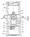
- the section (1) of the door closer shown in FIG. 1 has been shown in section.
- the closer shaft (2) is located inside the housing (1).
- the cam disc (3) is non-positively and positively connected to the closer shaft.
- Both the roller (13) and the force transmission roller (14) are in contact with the cam disc (3) via spring forces that lie behind the damping piston (10) and the spring support member (20).
- the roller (13) is located within the damping piston (10) and is rotatably supported in the damping piston (10) by an axle bolt (11).
- the power transmission roller (14) is also rotatably mounted within the spring support member (20) by means of an axle bolt (12).
- a force is transmitted against the spring support member (20) via the pressure spring (15) via the force transmission roller (14) to the cam disc (3).
- a spring (21) is also located behind the damping piston (10).
- two securing rods (8) are located within the spring support member (20). These locking bars run in the longitudinal axis of the closer housing and transverse to the closer shaft (2). They are firmly connected to the spring support member (20) via a non-positive and positive connection (18). This can happen, for example, in that heavy-duty locking pins are provided as securing rods (8), which sit with a press fit in the spring support member (20). It would also be possible to press them into the damping piston (10). It is crucial for the function of the safety rods (8) that they close to the closer shaft (2) To have position. They therefore run with appropriate play directly above the cam disc curve (3) and directly past the two sides of the longitudinal axis of the closer shaft (2).
- the closer shaft extension (9) is required to support the deep groove ball bearing located in the sealing plug (6), but not shown. In the area of the security rods (8), this shaft extension is interrupted by a groove to make room for the security rods (8). This measure ensures that the spring support member (20) cannot rotate with respect to the cam disc (3). The spring support member (20) would not change its position in relation to the cam disc (3) by either a right or a left turn.
- the locking rods (8) are made long enough so that they can be immersed smoothly with a clearance fit within the damping piston (10) in two blind holes (16).
- the depth and length of the blind bores (16) are dimensioned such that a sufficiently large free space (17) remains between the inserted safety rod end (19) and the end of the blind bore (16).
- This free space (17) must be dimensioned so deep that during the longitudinal movements of the damping piston (10) and the spring support member (20) the safety rods (8) do not stop (10) within the damping piston.
- the aforementioned blind bore (16) can also be present within the spring support member (20). It is important that at least two rods are used, because if only one rod were used, the damping piston (10) and the spring support member (20) might only be secured against one direction of rotation.
- round materials have been used as securing rods (8). These round bars or pins represent an inexpensive fuse and are also easy to handle when manufacturing the door closer. Square materials or other materials can of course also be used just as well.
Abstract
Description
Die Erfindung betrifft einen Türschließer nach dem Oberbegriff des Anspruchs 1.The invention relates to a door closer according to the preamble of claim 1.
Ein derartiger Schließer ist aus der DE-OS 33 45 004 bekannt geworden. Bei Türschließern dieser Art wird durch die Gestaltung der Kurvenbahnen, dem Federstützglied und auch dem Dämpfungskolben ja nach Türöffnungswinkel bzw. Drehwinkel vorbestimmte, an die Öffnungs- und Schließcharakteristik angepaßte Hübe zugeteilt. Die dem Faderstützglied zugeordnete Kurvenbahn erlaubt einen dem Drehwinkel der Schließerwelle zugeordneten Hub.Such a closer is known from DE-OS 33 45 004. In door closers of this type, predetermined strokes adapted to the opening and closing characteristics are assigned by the design of the cam tracks, the spring support member and also the damping piston depending on the door opening angle or angle of rotation. The cam track assigned to the fader support member permits a stroke assigned to the angle of rotation of the closer shaft.
Der DE-OS 20 41 099 ist ein Bodentürschließer zu entnehmen, bei dem das Verschiebeglied einer zweiten Dämpfungsvorrichtung gegen Verdrehung gesichert ist. Diese Verdrehsicherung wird durch einen in eine Nut hineinragenden Anschlag realisiert. Dadurch kann sich das Verschiebeglied bei einer Axialbewegung nicht verdrehen.DE-OS 20 41 099 shows a floor door closer in which the sliding member of a second damping device is secured against rotation. This protection against rotation is realized by a stop protruding into a groove. As a result, the sliding member cannot twist during an axial movement.
Die Aufgabe der Erfindung besteht darin, einen Türschließer der eingangs genannten Art zu schaffen, bei dem ein Verdrehen des Dämpfungskolbens und des Kraftübertragungsgliedes um die Längsachse gegenüber der Hubkurvenscheibe vermieden wird, d.h. sie müssen sich unabhängig voneinander in der Axialbewegung verschieben lassen können. Ebenfalls darf die Verdrehsicherung keinen Einfluß auf die verwendete Hubkurvenscheibe haben.The object of the invention is to provide a door closer of the type mentioned, in which a rotation of the damping piston and the force transmission member about the longitudinal axis with respect to the cam disc is avoided, ie they must be able to move independently of one another in the axial movement. Likewise, the anti-rotation device must not have any influence on the cam disc used.
Diese Aufgabe wird durch die kennzeichnenden Merkmale des Anspruchs 1 gelöst, und zwar so, daß Sicherungsmittel vorhanden sind, die ein Verdrehen des Dämpfungskolbens und des Federstützgliedes gegeneinander vermeiden. Durch die Anbringung der Sicherungsmittel wird die Funktion des Türschließers in keiner Weise beeinträchtigt. Als Sicherungsmittel werden zwei Stäbe verwendet, die vorteilhaft einerseits z.B. im Federstützglied fest verankert sind und andererseits auf der gegenüberliegenden Seite innerhalb des Dämpfungskolbens in Sackbohrungen reibungslos eintauchen können. Die Anordnung der Sicherungsstäbe geschieht an jeder Seite der Schließerwelle in Achsrichtung des Gehäuses. Dadurch ist es möglich, daß sich bei einem Verdrehen des Dämpfungskolbens oder des Federstützgliedes die Sicherungsstäbe entweder auf der einen oder anderen Seite an der Schließerwelle abstützen.This object is achieved by the characterizing features of claim 1, in such a way that securing means are present which prevent the damping piston and the spring support member from rotating against one another. The function of the door closer is in no way impaired by the attachment of the securing means. Two rods are used as securing means, which are advantageous on the one hand e.g. are firmly anchored in the spring support member and, on the other hand, can smoothly plunge into blind bores on the opposite side within the damping piston. The securing rods are arranged on each side of the closer shaft in the axial direction of the housing. This makes it possible that the locking rods are supported either on one or the other side of the closer shaft when the damping piston or the spring support member is rotated.
Will sich entweder der Dämpfungskolben oder aber auch das Federstützglied verdrehen, so ist dieses nicht möglich, denn die Sicherungsstäbe halten den Dämpfungskolben und das Federstützglied in ihrer ursprünglich montierten Lage fest.If either the damping piston or the spring support member wants to twist, this is not possible because the locking rods hold the damping piston and the spring support member in their originally installed position.
Ein Verdrehen um die eigene Achse entweder des Dämpfungskolbens oder des Federstützgliedes ist dann möglich, wenn die Tür in eine extreme Offenstellung gebracht wird. In dieser extremen Offenlage ist es möglich, daß durch den erhöhten Federdruck z.B. das Federstützglied sich um die eigene Achse dreht. Durch diese Verdrehung ist es nicht mehr sichergestellt, daß die Andruckrolle mit der Hubkurvenscheibe sicher im Eingriff steht. Ein reibungsloser Betrieb des Türschließers ist somit nicht gewährleistet. Um jedoch einen reibungslosen Betrieb zu garantieren, werden der Dämpfungskolben und das Federstützglied gegen Verdrehung um die eigene Achse gesichert, ohne daß dadurch die Funktion des Türschließers beeinträchtigt wird.Rotation around its own axis of either the damping piston or the spring support member is possible when the door is brought into an extreme open position. In this extreme open position it is possible that, for example, the spring support member rotates about its own axis due to the increased spring pressure. This rotation no longer ensures that the pressure roller is securely engaged with the cam disc. Smooth operation of the door closer is therefore not guaranteed. However, in order to guarantee smooth operation, the damping piston and the spring support member are secured against rotation about their own axis, without this affecting the function of the door closer.
In einer vorteilhaften Ausgestaltung des erfindungsgemäßen Gegenstandes ist es möglich, eine preiswerte Sicherung dahingehend zu schaffen, daß Rundstäbe zur Sicherung des Dämpfungskolbens und des Federstützgliedes verwendet werden. Ein Rundstab läßt sich kraft- und formschlüssig z.B. innerhalb des Federstützgliedes oder auch des Dämpfungskolbens verankern. Auf der gegenüberliegenden Seite befinden sich dann Freibohrungen, in denen diese Rundstäbe bei Betätigung des Türschließers ohne Reibung eintauchen können.In an advantageous embodiment of the object according to the invention, it is possible to provide an inexpensive fuse in such a way that round rods are used to secure the damping piston and the spring support member. A round bar can be positively and positively e.g. anchor within the spring support member or the damping piston. On the opposite side there are free bores in which these round bars can dip without friction when the door closer is actuated.
Die Sicherungsstifte stellen somit eine Verdrehsicherung der Kolben gegenüber der Hubkurvenscheibe dar. Dadurch ist immer gewährleistet, daß der Kolben oder das Federstützglied in ihrer Ursprungslage verbleiben. Werden das Federstützglied oder der Dämpfungskolben aus ihrer Ursprungslage heraus gebracht, so können die Rollen nicht mehr sauber mit der Hubkurvenscheibe zum Eingriff kommen. Es entsteht ein Schieben und Reiben, wodurch ein erhöhter Verschleiß des Türschließers gegeben ist. Auch stimmt der Dämpfungsgrad des Türschließers bei einer Verdrehung des Dämpfungskolbens oder des Federstützgliedes nicht mehr, weil andere Kräfte innerhalb des Türschließers zum Einsatz kommen. Bei einer Verdrehung des Federstützgliedes wird der Kraftverlauf von der Feder über die Rolle auf die Hubkurvenscheibe wesentlich schlechter, und damit sind die geforderten Schließmomente nicht mehr gegeben, was ein sicheres Schließen der Tür unter Umständen nicht gewährleistet.The locking pins thus represent a rotation lock of the pistons with respect to the cam disc. This always ensures that the piston or the spring support member remain in their original position. If the spring support member or the damping piston are brought out of their original position, the rollers can no longer come into engagement with the cam disc properly. There is a pushing and rubbing, which results in increased wear of the door closer. Also, the degree of damping of the door closer is no longer correct when the damping piston or the spring support member is turned, because other forces are used within the door closer. When the spring support member is rotated, the force curve from the spring via the roller to the cam disc is significantly worse, and the required closing torques are no longer provided, which may not ensure that the door is closed securely.
Ein Ausführungsbeispiel der Erfindung ist in der Zeichnung schematisch dargestellt und wird nachstehend näher erläutert. Es zeigt:
- Figur 1:
- Ein Türschließergehäuse im Ausschnitt mit Dämpfungskolben und Federstützglied und
- Figur 2:
- einen Schnitt durch die Längsachse der Schließerwelle und das Gehäuse
- Figure 1:
- A door closer housing in the cutout with damping piston and spring support and
- Figure 2:
- a section through the longitudinal axis of the closer shaft and the housing
Das in Figur 1 ausschnittsweise dargestellte Gehäuse (1) des Türschließers ist im Schnitt dargestellt worden. Innerhalb des Gehäuses (1) befindet sich die Schließerwelle (2). An der Schließerwelle ist die Hubkurvenscheibe (3) kraft- und formschlüssig verbunden. Mit der Hubkurvenscheibe (3) sind sowohl die Rolle (13) als auch die Kraftübertragungsrolle (14) über Federkräfte, die hinter dem Dämpfungskolben (10) und dem Federstützglied (20) liegen, in Kontakt. Die Rolle (13) befindet sich innerhalb des Dämpfungskolbens (10) und wird durch einen Achsbolzen (11) drehbar im Dämpfungskolben (10) gelagert. Ebenso ist die Kraftübertragungsrolle (14) innerhalb des Federstützgliedes (20) durch einen Achsbolzen (12) drehbar gelagert. Gegen das Federstützglied (20) wird eine Kraft über die Druckfeder (15) über die Kraftübertragungsrolle (14) auf die Hubkurvenscheibe (3) übertragen. Hinter dem Dämpfungskolben (10) befindet sich ebenfalls eine Feder (21). Aufgrund der Federkräfte der Federn (21) und (15) ist es sichergestellt, daß die Rolle (13) und die Kraftübertragungsrolle (14) immer an der Hubscheibenkurve (3) anliegen. Bei Betätigung der Schließerwelle wird die Hubkurvenscheibe (3) verdreht, und der Dämpfungskolben (10) sowie das Federstützglied (20) führen innerhalb des Gehäuses (1) eine gleitende Bewegung aus.The section (1) of the door closer shown in FIG. 1 has been shown in section. The closer shaft (2) is located inside the housing (1). The cam disc (3) is non-positively and positively connected to the closer shaft. Both the roller (13) and the force transmission roller (14) are in contact with the cam disc (3) via spring forces that lie behind the damping piston (10) and the spring support member (20). The roller (13) is located within the damping piston (10) and is rotatably supported in the damping piston (10) by an axle bolt (11). The power transmission roller (14) is also rotatably mounted within the spring support member (20) by means of an axle bolt (12). A force is transmitted against the spring support member (20) via the pressure spring (15) via the force transmission roller (14) to the cam disc (3). A spring (21) is also located behind the damping piston (10). Due to the spring forces of the springs (21) and (15), it is ensured that the roller (13) and the force transmission roller (14) always rest on the cam disc curve (3). When the closer shaft is actuated, the cam disc (3) is rotated and the damping piston (10) and the spring support member (20) execute a sliding movement within the housing (1).
Wie in dem Ausführungsbeispiel dargestellt, befinden sich innerhalb des Federstützgliedes (20) zwei Sicherungsstäbe (8). Diese Sicherungsstäbe verlaufen in Längsachse des Schließergehäuses und quer zur Schließerwelle (2). Sie sind mit dem Federstützglied (20) über eine kraft- und formschlüssige Verbindung (18) fest verbunden. Dieses kann z.B. dadurch geschehen, daß als Sicherungsstäbe (8) Schwerspannstifte vorgesehen werden, die mit einem Preßsitz in dem Federstützglied (20) sitzen. Es wäre genauso gut möglich, diese in den Dämpfungskolben (10) einzudrücken. Entscheidend für die Funktion der Sicherungsstäbe (8) ist es, daß sie dicht an der Schließerwelle (2) ihre Position haben. Sie verlaufen deshalb mit entsprechendem Spiel direkt oberhalb der Hubscheibenkurve (3) und direkt an den beiden Seiten der Längsachse der Schließerwelle (2) vorbei. Oberhalb der Sicherungsstäbe (8) kann sich noch ein Schließerwellenansatz (9) befinden, der die Sicherungsstäbe (8) quasi einbettet. Nach oben hin wird der Schließerwellenansatz (9) benötigt, um das sich im Verschlußstopfen (6) befindliche, jedoch nicht dargestellte Rillenkugellager abzustützen. Im Bereich der Sicherungsstäbe (8) ist dieser Wellenansatz durch eine Nut unterbrochen, um Platz für die Sicherungsstäbe (8) zu schaffen. Durch diese Maßnahme ist es sichergestellt, daß das Federstützglied (20) sich nicht gegenüber der Hubkurvenscheibe (3) verdrehen kann. Weder durch eine Rechts- noch durch eine Linksdrehung würde das Federstützglied (20) seine Position gegenüber der Hubkurvenscheibe (3) verändern.As shown in the exemplary embodiment, two securing rods (8) are located within the spring support member (20). These locking bars run in the longitudinal axis of the closer housing and transverse to the closer shaft (2). They are firmly connected to the spring support member (20) via a non-positive and positive connection (18). This can happen, for example, in that heavy-duty locking pins are provided as securing rods (8), which sit with a press fit in the spring support member (20). It would also be possible to press them into the damping piston (10). It is crucial for the function of the safety rods (8) that they close to the closer shaft (2) To have position. They therefore run with appropriate play directly above the cam disc curve (3) and directly past the two sides of the longitudinal axis of the closer shaft (2). Above the locking bars (8) there can also be a closer shaft extension (9) which virtually embeds the locking bars (8). At the top, the closer shaft extension (9) is required to support the deep groove ball bearing located in the sealing plug (6), but not shown. In the area of the security rods (8), this shaft extension is interrupted by a groove to make room for the security rods (8). This measure ensures that the spring support member (20) cannot rotate with respect to the cam disc (3). The spring support member (20) would not change its position in relation to the cam disc (3) by either a right or a left turn.
Damit auch der gegenüberliegende Dämpfungskolben (10) eine Sicherung gegen Verdrehung erfährt, werden die Sicherungsstäbe (8) entsprechend lang ausgeführt, so daß sie mit einer Spielpassung innerhalb des Dämpfungskolbens (10) in zwei Sackbohrungen (16) reibungslos eintauchen können. Die Sackbohrungen (16) sind in ihrer Tiefe bzw. Länge so bemessen, daß zwischen dem eingeführten Sicherungsstabende (19) und dem Ende der Sackbohrung (16) noch ein genügend großer Freiraum (17) verbleibt. Dieser Freiraum (17) muß so tief bemessen sein, daß bei den Längsbewegungen des Dämpfungskolbens (10) und des Federstützgliedes (20) ein Anschlag der Sicherungsstäbe (8) innerhalb des Dämpfungskolbens nicht (10) stattfindet. Umgekehrt kann auch innerhalb des Federstützgliedes (20) die bereits vorerwähnte Sackbohrung (16) vorhanden sein. Wichtig ist es, daß mindestens zwei Stäbe verwendet werden, denn würde nur ein Stab verwendet, so wären der Dämpfungskolben (10) und das Federstützglied (20) unter Umständen nur gegen eine Drehrichtung gesichert.So that the opposite damping piston (10) is secured against rotation, the locking rods (8) are made long enough so that they can be immersed smoothly with a clearance fit within the damping piston (10) in two blind holes (16). The depth and length of the blind bores (16) are dimensioned such that a sufficiently large free space (17) remains between the inserted safety rod end (19) and the end of the blind bore (16). This free space (17) must be dimensioned so deep that during the longitudinal movements of the damping piston (10) and the spring support member (20) the safety rods (8) do not stop (10) within the damping piston. Conversely, the aforementioned blind bore (16) can also be present within the spring support member (20). It is important that at least two rods are used, because if only one rod were used, the damping piston (10) and the spring support member (20) might only be secured against one direction of rotation.
In dem dargestellten Ausführungsbeispiel sind als Sicherungsstäbe (8) Rundmaterialien verwendet worden. Diese Rundstäbe oder Stifte stellen eine preiswerte Sicherung dar und sind auch bei der Herstellung des Türschließers leicht zu handhaben. Genauso gut können natürlich auch Vierkantmaterialien oder anderes Material verwendet werden.In the illustrated embodiment, round materials have been used as securing rods (8). These round bars or pins represent an inexpensive fuse and are also easy to handle when manufacturing the door closer. Square materials or other materials can of course also be used just as well.
- 11
- Gehäusecasing
- 22nd
- SchließerwelleCloser shaft
- 33rd
- HubkurvenscheibeCam disc
- 66
- VerschlußstopfenSealing plug
- 88th
- SicherungsstäbeSafety rods
- 99
- SchließerwellenansatzNO shaft approach
- 1010th
- DämpfungskolbenDamping piston
- 1111
- AchsbolzenAxle bolts
- 1212
- AchsbolzenAxle bolts
- 1313
- Rollerole
- 1414
- KraftübertragungsrollePower transmission roller
- 1515
- DruckfederCompression spring
- 1616
- SackbohrungBlind hole
- 1717th
- Freiraumfree space
- 1818th
- Verbindungconnection
- 1919th
- SicherungsstabendeSafety rod end
- 2020th
- FederstützgliedSpring support member
- 2121
- Federfeather
Claims (5)
- A door closer comprising a closer shaft (2) adapted to be actuated in the closing direction by a spring system, and a damping piston (10) operatively connected to the closer shaft, and also comprising a pivotable actuating arm coupled to the closer shaft outside the housing (1), and a cam disc (3) non-positively connected to the closer shaft (2) inside the housing (1), the cam track associated with the opening direction being subject to the action of a spring support element (20) by way of at least one roller (14) while the cam track associated with the closing direction is subject to the action of a damping piston (10) by way of another roller (13), characterized in that the spring support element (20) and the damping piston (10) are disposed so as to be non-rotatable with respect to the cam disc (3) and in that the antirotation means is formed by at least two locking rods (8) extending in the axial direction of the housing and traverseley of the axial direction of the closer shaft (2), at least one locking rod (8) extending on each side of the closer shaft (2).
- A door closer according to claim 1, characterized in that the locking rods (8) together with the spring support element (20) form a non-positive and positive connection (18) and can penetrate without friction into a free bore (blind bore 16) in the damping piston (10).
- A door closer according to claim 1, characterized in that the locking rods (8) together with the damping piston (10) form a non-positive and positive connection (18) and can penetrate without friction into a free bore (blind bore 16) in the spring support element (20).
- A door closer according to claims 1 to 3, characterized in that the locking rods (8) consist of a round material.
- A door closer according to claims 1 to 4, characterized in that the locking rods (8) are formed as heavy dowel pins or adapter sleeves.
Priority Applications (1)
| Application Number | Priority Date | Filing Date | Title |
|---|---|---|---|
| AT91120383T ATE90137T1 (en) | 1990-12-24 | 1991-11-28 | DOOR CLOSER. |
Applications Claiming Priority (2)
| Application Number | Priority Date | Filing Date | Title |
|---|---|---|---|
| DE4041824 | 1990-12-24 | ||
| DE4041824A DE4041824C1 (en) | 1990-12-24 | 1990-12-24 |
Publications (2)
| Publication Number | Publication Date |
|---|---|
| EP0492175A1 EP0492175A1 (en) | 1992-07-01 |
| EP0492175B1 true EP0492175B1 (en) | 1993-06-02 |
Family
ID=6421471
Family Applications (1)
| Application Number | Title | Priority Date | Filing Date |
|---|---|---|---|
| EP91120383A Expired - Lifetime EP0492175B1 (en) | 1990-12-24 | 1991-11-28 | Door closer |
Country Status (4)
| Country | Link |
|---|---|
| EP (1) | EP0492175B1 (en) |
| AT (1) | ATE90137T1 (en) |
| DE (2) | DE4041824C1 (en) |
| ES (1) | ES2032728T3 (en) |
Families Citing this family (8)
| Publication number | Priority date | Publication date | Assignee | Title |
|---|---|---|---|---|
| DE9209276U1 (en) * | 1992-07-10 | 1992-08-27 | Dorma Gmbh + Co. Kg, 5828 Ennepetal, De | |
| DE19603186C2 (en) * | 1996-01-30 | 1998-02-19 | Dorma Gmbh & Co Kg | Overhead door closer |
| DE19922916A1 (en) * | 1999-01-18 | 2000-07-20 | Geze Gmbh | Door closer with drive for closing door casement has spring piston and damping piston mounted rotationally secured relative to stroke cam plate through interaction with drive housing |
| DE102004041358B4 (en) * | 2004-08-25 | 2006-07-13 | Dorma Gmbh + Co. Kg | Overhead closer |
| DE102004061624C5 (en) | 2004-12-17 | 2011-02-03 | Dorma Gmbh + Co. Kg | Door drive, in particular revolving door anti-theft |
| DE102004061627B4 (en) * | 2004-12-17 | 2007-02-01 | Dorma Gmbh + Co. Kg | door closers |
| CN101135216B (en) * | 2006-09-01 | 2012-12-12 | 多玛两合有限公司 | Upper door closer |
| EP3683393B1 (en) * | 2019-01-16 | 2021-03-03 | dormakaba Deutschland GmbH | Door actuator |
Family Cites Families (4)
| Publication number | Priority date | Publication date | Assignee | Title |
|---|---|---|---|---|
| GB745271A (en) * | 1953-10-02 | 1956-02-22 | Newman William & Sons Ltd | Improvements relating to spring door-closing appliances |
| DE2041099A1 (en) * | 1970-08-19 | 1972-02-24 | Ver Baubeschlag Gretsch Co | Door closers, in particular floor door closers |
| GB1344945A (en) * | 1972-01-06 | 1974-01-23 | Gibbons Ld James | Doorclosing mechanism |
| DE3345004A1 (en) * | 1983-12-13 | 1985-06-13 | Dorma-Baubeschlag Gmbh & Co Kg, 5828 Ennepetal | OVERCLOSE |
-
1990
- 1990-12-24 DE DE4041824A patent/DE4041824C1/de not_active Expired - Fee Related
-
1991
- 1991-11-28 ES ES199191120383T patent/ES2032728T3/en not_active Expired - Lifetime
- 1991-11-28 EP EP91120383A patent/EP0492175B1/en not_active Expired - Lifetime
- 1991-11-28 AT AT91120383T patent/ATE90137T1/en not_active IP Right Cessation
- 1991-11-28 DE DE9191120383T patent/DE59100134D1/en not_active Expired - Lifetime
Also Published As
| Publication number | Publication date |
|---|---|
| DE59100134D1 (en) | 1993-07-08 |
| DE4041824C1 (en) | 1992-06-11 |
| ATE90137T1 (en) | 1993-06-15 |
| EP0492175A1 (en) | 1992-07-01 |
| ES2032728T3 (en) | 1993-12-01 |
| ES2032728T1 (en) | 1993-03-01 |
Similar Documents
| Publication | Publication Date | Title |
|---|---|---|
| DE19506220C2 (en) | Door closer | |
| DE4038720C2 (en) | Upper door closer with slide rail linkage | |
| DE19922916A1 (en) | Door closer with drive for closing door casement has spring piston and damping piston mounted rotationally secured relative to stroke cam plate through interaction with drive housing | |
| DE19506355C2 (en) | Automatic door closer | |
| EP0492175B1 (en) | Door closer | |
| DE2821766C3 (en) | Butterfly valve | |
| DE3425909A1 (en) | SPRING MONITORING DEVICE | |
| EP1239496B1 (en) | Hinge with switch | |
| EP0597170B1 (en) | Rotary bolt locking | |
| EP0830491B1 (en) | Overhead door-closing unit | |
| DE3844627A1 (en) | Window, door or the like which is equipped with closure means | |
| DE10031403C2 (en) | Overhead door closer with a slide rail arrangement | |
| EP1431497A2 (en) | Free running device for a wing control of a door or window | |
| DE1915751C3 (en) | Swivel mounting for door straps of door arresters for motor vehicle doors | |
| EP3344881B1 (en) | Hydromechanical blocking cylinder and hydraulic control system for actuating same | |
| EP2818618B1 (en) | Device for regulating the closing sequence of a two-leaf revolving door assembly | |
| DE102006002751A1 (en) | Swing door drive with cam disk for opening and closing of door, has swing drive which is mutually rotated about one eighty degree with an alternate pull to actuating rod and has mutual coupling | |
| EP3927997A1 (en) | Ball screw drive with an anti-rotation safeguard | |
| DE3228933A1 (en) | SWIVEL BEARINGS FOR DOORS, ESPECIALLY FOR PENDULAR DOORS | |
| DE3823718A1 (en) | DEVICE FOR LIMITING AND ADJUSTING THE SWITCHING PATH IN FITTINGS | |
| EP0861953A1 (en) | Operating handle | |
| DE19532262A1 (en) | Closure sequence regulation device for double-panelled door | |
| DE102008044772B3 (en) | Rotary-check valve for protecting leakage of fluid in e.g. foodstuff industry, has rotary-shut-off valves controlling inlet opening using closing element e.g. seat disk, and outlet opening using another closing element | |
| DE3901936C2 (en) | Espagnolette lock | |
| DE3538883C2 (en) |
Legal Events
| Date | Code | Title | Description |
|---|---|---|---|
| PUAI | Public reference made under article 153(3) epc to a published international application that has entered the european phase |
Free format text: ORIGINAL CODE: 0009012 |
|
| ITCL | It: translation for ep claims filed |
Representative=s name: DE DOMINICIS & MAYER S.R.L. |
|
| 17P | Request for examination filed |
Effective date: 19920401 |
|
| AK | Designated contracting states |
Kind code of ref document: A1 Designated state(s): AT BE CH DE ES FR GB IT LI NL |
|
| GBC | Gb: translation of claims filed (gb section 78(7)/1977) | ||
| TCNL | Nl: translation of patent claims filed | ||
| EL | Fr: translation of claims filed | ||
| 17Q | First examination report despatched |
Effective date: 19921027 |
|
| ITF | It: translation for a ep patent filed |
Owner name: DE DOMINICIS & MAYER S.R.L. |
|
| GRAA | (expected) grant |
Free format text: ORIGINAL CODE: 0009210 |
|
| STAA | Information on the status of an ep patent application or granted ep patent |
Free format text: STATUS: THE PATENT HAS BEEN GRANTED |
|
| AK | Designated contracting states |
Kind code of ref document: B1 Designated state(s): AT BE CH DE ES FR GB IT LI NL |
|
| REF | Corresponds to: |
Ref document number: 90137 Country of ref document: AT Date of ref document: 19930615 Kind code of ref document: T |
|
| ET | Fr: translation filed | ||
| GBT | Gb: translation of ep patent filed (gb section 77(6)(a)/1977) |
Effective date: 19930609 |
|
| REF | Corresponds to: |
Ref document number: 59100134 Country of ref document: DE Date of ref document: 19930708 |
|
| ET1 | Fr: translation filed ** revision of the translation of the patent or the claims | ||
| REG | Reference to a national code |
Ref country code: ES Ref legal event code: FG2A Ref document number: 2032728 Country of ref document: ES Kind code of ref document: T3 |
|
| PLBE | No opposition filed within time limit |
Free format text: ORIGINAL CODE: 0009261 |
|
| 26N | No opposition filed | ||
| EL | Fr: translation of claims filed |
Free format text: BO 23/93 DU 930611 LA MENTION DE LA REMISE DE LA TRADUCTION DU BOPI 93/23 EST A CONSIDERER COMME NULLE ET NON AVENUE BO 27/93 DU 930709 LA MENTION DE LA REMISE DE LA TRADUCTION REVISEE DU BOPI 93/27 EST A CONSIDERER COMME TRADUCTION REMISE |
|
| REG | Reference to a national code |
Ref country code: GB Ref legal event code: IF02 |
|
| PG25 | Lapsed in a contracting state [announced via postgrant information from national office to epo] |
Ref country code: IT Free format text: LAPSE BECAUSE OF NON-PAYMENT OF DUE FEES;WARNING: LAPSES OF ITALIAN PATENTS WITH EFFECTIVE DATE BEFORE 2007 MAY HAVE OCCURRED AT ANY TIME BEFORE 2007. THE CORRECT EFFECTIVE DATE MAY BE DIFFERENT FROM THE ONE RECORDED. Effective date: 20051128 |
|
| REG | Reference to a national code |
Ref country code: CH Ref legal event code: PCOW Free format text: DORMA GMBH + CO. KG;DORMA PLATZ 1;58256 ENNEPETAL (DE) |
|
| PGFP | Annual fee paid to national office [announced via postgrant information from national office to epo] |
Ref country code: FR Payment date: 20101130 Year of fee payment: 20 Ref country code: NL Payment date: 20101111 Year of fee payment: 20 Ref country code: AT Payment date: 20101112 Year of fee payment: 20 |
|
| PGFP | Annual fee paid to national office [announced via postgrant information from national office to epo] |
Ref country code: CH Payment date: 20101123 Year of fee payment: 20 Ref country code: DE Payment date: 20101119 Year of fee payment: 20 |
|
| REG | Reference to a national code |
Ref country code: CH Ref legal event code: PFA Owner name: DORMA GMBH + CO. KG Free format text: DORMA GMBH + CO. KG#DORMA PLATZ 1#58256 ENNEPETAL (DE) -TRANSFER TO- DORMA GMBH + CO. KG#DORMA PLATZ 1#58256 ENNEPETAL (DE) |
|
| PGFP | Annual fee paid to national office [announced via postgrant information from national office to epo] |
Ref country code: GB Payment date: 20101118 Year of fee payment: 20 Ref country code: BE Payment date: 20101117 Year of fee payment: 20 |
|
| PGFP | Annual fee paid to national office [announced via postgrant information from national office to epo] |
Ref country code: ES Payment date: 20101124 Year of fee payment: 20 |
|
| REG | Reference to a national code |
Ref country code: DE Ref legal event code: R071 Ref document number: 59100134 Country of ref document: DE |
|
| REG | Reference to a national code |
Ref country code: DE Ref legal event code: R071 Ref document number: 59100134 Country of ref document: DE |
|
| BE20 | Be: patent expired |
Owner name: *DORMA G.M.B.H. + CO. K.G. Effective date: 20111128 |
|
| REG | Reference to a national code |
Ref country code: NL Ref legal event code: V4 Effective date: 20111128 |
|
| REG | Reference to a national code |
Ref country code: CH Ref legal event code: PL |
|
| REG | Reference to a national code |
Ref country code: GB Ref legal event code: PE20 Expiry date: 20111127 |
|
| PG25 | Lapsed in a contracting state [announced via postgrant information from national office to epo] |
Ref country code: NL Free format text: LAPSE BECAUSE OF EXPIRATION OF PROTECTION Effective date: 20111128 |
|
| REG | Reference to a national code |
Ref country code: AT Ref legal event code: MK07 Ref document number: 90137 Country of ref document: AT Kind code of ref document: T Effective date: 20111128 |
|
| PG25 | Lapsed in a contracting state [announced via postgrant information from national office to epo] |
Ref country code: GB Free format text: LAPSE BECAUSE OF EXPIRATION OF PROTECTION Effective date: 20111127 |
|
| PG25 | Lapsed in a contracting state [announced via postgrant information from national office to epo] |
Ref country code: DE Free format text: LAPSE BECAUSE OF EXPIRATION OF PROTECTION Effective date: 20111129 |
|
| REG | Reference to a national code |
Ref country code: ES Ref legal event code: FD2A Effective date: 20130802 |
|
| PG25 | Lapsed in a contracting state [announced via postgrant information from national office to epo] |
Ref country code: ES Free format text: LAPSE BECAUSE OF EXPIRATION OF PROTECTION Effective date: 20111129 |