EP0488412B1 - Gerät zur Erzeugung von Farbbildern - Google Patents
Gerät zur Erzeugung von Farbbildern Download PDFInfo
- Publication number
- EP0488412B1 EP0488412B1 EP91120617A EP91120617A EP0488412B1 EP 0488412 B1 EP0488412 B1 EP 0488412B1 EP 91120617 A EP91120617 A EP 91120617A EP 91120617 A EP91120617 A EP 91120617A EP 0488412 B1 EP0488412 B1 EP 0488412B1
- Authority
- EP
- European Patent Office
- Prior art keywords
- color
- image
- black
- toner
- glossiness
- Prior art date
- Legal status (The legal status is an assumption and is not a legal conclusion. Google has not performed a legal analysis and makes no representation as to the accuracy of the status listed.)
- Expired - Lifetime
Links
Images


Classifications
-
- H—ELECTRICITY
- H04—ELECTRIC COMMUNICATION TECHNIQUE
- H04N—PICTORIAL COMMUNICATION, e.g. TELEVISION
- H04N1/00—Scanning, transmission or reproduction of documents or the like, e.g. facsimile transmission; Details thereof
- H04N1/46—Colour picture communication systems
- H04N1/56—Processing of colour picture signals
- H04N1/60—Colour correction or control
- H04N1/6016—Conversion to subtractive colour signals
- H04N1/6022—Generating a fourth subtractive colour signal, e.g. under colour removal, black masking
-
- G—PHYSICS
- G03—PHOTOGRAPHY; CINEMATOGRAPHY; ANALOGOUS TECHNIQUES USING WAVES OTHER THAN OPTICAL WAVES; ELECTROGRAPHY; HOLOGRAPHY
- G03G—ELECTROGRAPHY; ELECTROPHOTOGRAPHY; MAGNETOGRAPHY
- G03G15/00—Apparatus for electrographic processes using a charge pattern
- G03G15/01—Apparatus for electrographic processes using a charge pattern for producing multicoloured copies
Definitions
- the present invention relates to a color image processing apparatus for forming a color image by mixing a plurality of coloring agents.
- a conventional electrophotographic color image processing apparatus forms a color image by a method comprising the steps of: a latent image forming process in which a color image, the color of which has been decomposed into four colors, that is, yellow, magenta, cyan and black, is exposed and formed on the surface of an image carrier such as a photosensitive drum, which has been uniformly charged, by a laser beam serving as an exposure means according to the present invention; a development process for developing the latent image formed on the photosensitive drum into a toner image (a visible image); a transfer process for transferring the toner image formed on the photosensitive drum to the surface of recording paper; and a fixing process for fixing the toner image formed on the recording paper.
- a latent image forming process in which a color image, the color of which has been decomposed into four colors, that is, yellow, magenta, cyan and black, is exposed and formed on the surface of an image carrier such as a photosensitive drum, which has been uniformly charged, by a laser beam serving as
- an electrophotographic color copying machine serving as an application example of the color image processing apparatus according to the present invention reads an original color image while decomposing the color into three colors, that is, red (R), green (G) and blue (B) and they are color-converted into CMY density signals, which are the complementary signals of RGB so that a color signal of the substractive mixture type which uses toner is obtained.
- a black (BK) signal is formed in addition to the YMC density signals so that the image is formed by using color toners of four colors, that is, yellow, magenta, cyan and black. That is, the black toner is used to perform the under color removal in which black realized by toner is employed in place of black obtained from the YMC three-color mixture.
- the under color removal is performed by using the black toner, it is considered that the following effects can be obtained:
- the toner has a low melting point (140 to 150°C) so as to be dissolved and mixed with other color toners in order to improve the color reproducibility of a color image.
- a black toner for use in a conventional white and black copying machine is arranged to possess a high melting point (180 to 190°C) for the purpose of raising the copying speed and improving the durability because of its high frequency in use.
- the color toners can be dissolved by heat in the fixing process in which the toners are fixed to a recording paper sheet, the black toner cannot be satisfactorily dissolved.
- the colorless black toner image regions involve uneven portions on their surfaces in a microscopic view. Therefore, light made incident upon the paper surface can be diffused and reflected, causing the glossiness of the surface of the image to be deteriorated.
- the surface of the image region formed by the color toners is smooth enough to regularly reflect light made incident upon the surface of the paper. As a result, the above-described region displays excellent glossiness.
- Each of the above-described two methods is arranged in such a manner that the heating value to be given to the toner is changed to adjust the degree at which the toner is melted so as to change the surface condition of the image. Thus, the glossiness is changed.
- the above-described methods are necessarily arranged in such a manner that the essential factors for forming the image, such as the color mixture characteristics and fixing characteristics, are changed undesirably. Therefore, an image exhibiting excellent quality cannot be obtained because the glossiness, the color tone and adhesive force can be changed. Furthermore, since the fixing process is performed in a state where the fixing conditions are not suitable for the life of the fixing roller, the fixing roller can easily be deteriorated.
- the conventional full color copying machine has been arranged in such a manner that the melting points of the magenta, cyan, yellow and black toners are made to be closer to one another as much as possible to prevent the undesirable change in the glossiness of one color.
- the melting point of the black toner for use in the above-described conventional color copying machine is lower than that of the toner for use in the ordinary monochromatic copying machine. Therefore, the glossiness of the black image, for example, that of a black line image such as a black character, is raised excessively. Therefore, there arises a problem in that the formed image cannot easily be recognized depending upon the way of placing the light source for use to observe the formed image.
- the four color decomposition algorithm for obtaining chromaticity (color tone) required by a user has different optimum value which is determined depending upon the type and the characteristics of the recording medium such as the surface flatness, the chromaticity and the whiteness of the recording medium and as well as a fact that the recording medium is used to form a transparent image or a reflected image. Therefore, images exhibiting high quality cannot always be obtained regardless of the type of the recording medium. Furthermore, in order to obtain an image (hereinafter called an "OHP image”) for use in an over head projector, the image must have high transparency.
- JP-A-114 2740 discloses the deposition of four toner colors including black on a transfer material.
- An object of the present invention is to provide a color image processing apparatus capable of overcoming the above-described problems.
- Another object of the present invention is to provide a color image processing apparatus capable of forming a glossy image while using cheap coloring agents.
- Another object of the present invention is to provide a color image processing apparatus capable of forming an image having desired glossiness by adjusting the quantity of a coloring agent of a predetermined color.
- Another object of the present invention is to provide a color image processing apparatus capable of forming an image exhibiting high quality by changing the glossiness of the image in accordance with the tone image region and the line image region.
- Another object of the present invention is to provide a color image processing apparatus capable of always stably forming a color image by determining the algorithm for converting the original image into image signals for each color in accordance with the characteristics of the recording medium.
- Another object of the present invention is to provide a color image processing apparatus capable of forming an image having desired glossiness by performing an image forming process in which a coloring agent having low glossiness is used before an image forming process in which a coloring agent having high glossiness is used is performed.
- a magenta toner was employed which was composed of 100 parts by weight of polyester main binder, 4 parts by weight of C.I. solvent red 49 serving as a pigment, 0.7 parts by weight of C.I. pigment red 122 serving as a dyestuff, 4 parts by weight of a charge controller and an additive.
- a cyan toner was composed of 100 parts by weight of polyester main binder, 5 parts by weight of phthalocyanine pigment, 4 parts by weight of a charge controller and an additive.
- a yellow toner was composed of 100 parts of polyester main binder, 5 parts by weight of C.I. pigment yellow 17, 4 parts of a charge controller and an additive.
- a black toner is composed of 100 parts by weight of polyester main binder, 60 parts by weight of a magnetic material, 2 parts by weight of a charge controller, 3 parts of a fixing agent and an additive.
- a fixing apparatus comprised of a pair composed of a fixing roller made of silicone rubber and a pressure roller arranged in such a manner that silicone rubber is coated with fluororubber.
- the temperature of the surface of the roller was made to be 180°C.
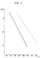
- the temperature and the viscosity characteristics of the above-described magenta toner, cyan toner and the yellow toner were arranged as designated by a continuous line of Fig. 1.
- the temperature and the viscosity characteristics of the black toner were arranged as designated by a dashed line of Fig. 1.
- the softening point of the toner according to this embodiment was made to be a temperature at which the viscosity was made to be 10 5 poise.
- the melting point of the magenta, the cyan and the yellow toners was 110°C, while that of the black toner was 135°C.
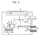
- Fig. 2 is a cross sectional view which schematically illustrates the structure of an embodiment of a full color copying apparatus according to the present invention.
- an original document 11 is exposed to light of an exposure lamp 9 so that reflected light from the same is imaged on an image sensor 10 comprising, for example, a CCD.
- the image sensor 10 has red, green and blue color filters fitted thereto so that red, green and blue image signals are transmitted.
- the image signals are then converted into image signals corresponding to cyan, yellow, magenta and black by a circuit to be described later.
- the surface of the photoconductive photosensitive drum 1 is exposed to a laser beam emitted from a laser beam scanner 2 and modified in accordance with each image signal.
- a latent image formed on the surface of the photosensitive drum 1 is sequentially developed by a development device 3 by C (cyan), M (magenta), Y (yellow) and BK (black) toners.
- the toner images obtained by the development process are sequentially transferred to the surface of a recording medium 14 electostatically absorbed/secured to the surface of a transfer drum 4. Then, the above-described recording medium 14 is separated by a scraping claw 17 before it is exhaust onto the surface of an exhaust tray 19 after it has passed through a conveyance belt 18 and a fixing roller 8.
- reference numeral 3BK represents a black image developer
- 3Y represents yellow image developer
- 3M represents a magenta image developer
- 3C represents a cyan image developer.
- Reference numeral 5 represents a cleaner 6 represents a primary charger
- 7 represents a transfer charger
- 12 represents a pre-exposure lamp
- 13 represents a discharger.
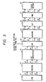
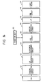
- Fig. 3 is a block diagram which illustrates an image signal processing circuit for forming a digital full color image.
- R (red), G (green) and B (blue) image brightness signals (RGB brightness signal) read by a CCD 21 are subjected to a process in which scatter between the light receiving cells (between pixels) is corrected by a shading correction circuit 22.
- a LOG conversion circuit 23 converts the RGB brightness signals supplied from the shading correction circuit 22 into C (cyan), M (magent) and Y (yellow) image density signals.
- a process is performed in which a black component formed by mixing the C, M and Y toners is replaced by the BK (black) toner in a case of a low brightness color, that is, in a case of a color signal inclined toward black.
- the above-described UCR process is also called "black color generation”.
- the UCR circuit 24 enables the quantity of the toner to be reduced and reproducibility of a pure black image which cannot easily be obtained by mixing C, M and Y to be improved by using the exclusive black (BK) toner.
- a masking circuit 25 which receives the C, M, Y and BK signals supplied from the UCR circuit 24 converts the C, M, Y and BK signals to adapt to the color reproduction characteristics of the printer. Furthermore, a look-up (LUT) table 26 comprising a ROM converts the same to adapt to the tone characteristics of the printer. Then, a pulse width modulation (PWM) circuit 27 converts them into pulse width signal which correspond to the density for expressing the density by an area tone method. The pulse width signal thus-formed is supplied to a laser drive 28 so that the surface of the photosensitive drum is scanned and exposed to the laser beam. As a result, the latent image is formed.
- PWM pulse width modulation
- the UCR circuit 24 receives a glossiness selection signal supplied from a CPU (omitted from illustration) so that the quantity of UCR to be performed in the UCR circuit 24 is controlled, the glossiness selection signal being a signal transmitted from the CPU in response to a command issued from a manipulating portion (omitted from illustration).
- the latent images are developed by the corresponding color toner development devices which correspond to the color latent images in accordance with a conventional electrophotography process.
- the color toner images are transferred to the surface of the recording medium in a multiplied manner before the transferred images are fixed so that a full color image is formed.
- the rate of black color generation in the UCR process is adjusted by using the above-described toners, the fixing devices and the image processing means so that the glossiness of the image formed on the recording medium is changed. Furthermore, the fixing device composed of a pair of rollers is used to perform fixing under the same condition.
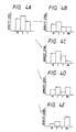
- Fig. 4A illustrates the level of the density signals for a pixel of the original document after it has been LOG-converted.
- Fig. 4B illustrates the level of the density signals which has been subjected to 50%-black color generation (the UCR process).
- the glossiness of the full color image formed on the recording medium after it has been subjected to the black color generation at the above-described rate shown in Fig. 4B was 33% under the fixing condition according to this embodiment. Furthermore, the glossiness of the full color image formed on the recording medium after it has been subjected to the black color generation at a rate of 25% shown in Fig. 4C was 54%. In addition, the glossiness of the full color image formed on the recording medium after it has been subjected to the black color generation at a rate of 75% shown in Fig. 4D was 11%.
- the above-described phenomenon can be considered that the black toner which forms the final layer, in accordance with its quantity, adjusts the glossiness of each of the other three color toners because the black toner has higher softening point than those of the other three toners.
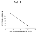
- the above-described three points were selected to determine the rate of black color generation. However, it can be gradually adjusted by determining the rate of black color generation as shown in Fig. 5.
- a glossiness required by a user can be set while maintaining the degree of fixing and the color grade.
- the deterioration in the fixing roller can be prevented and thereby an excellent image can be obtained.
- the softening point of the black toner be higher than that of each of the other three color toners by 10°C or more.
- the toner fixing device and the image processing means according to the first embodiment are used. Furthermore, a glossiness meter is used for the purpose of reading the glossiness of the original image region at the time of reading the original document. Then a CPU adjusts the rate of black color generation in accordance with the measured value of the glossiness. The rate of the black color generation is selected from the glossiness of the output image shown in Fig. 5. As a result, the same glossiness as that of the original document can be reproduced so that an image further like the original document can be formed in comparison to the case where the glossiness is simply selected.
- the above-described method may, of course, be employed together with the function of selecting the glossiness. As a result, the glossiness of the original document can be reproduced and a further excellent image quality can be obtained.
- the toner the fixing devices and the image processing means are employed and the rate of the black color generation in the UCR process is adjusted by the density of the color.
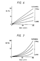
- Fig. 6 illustrates an example of the rate of the black color generation in the UCR process.
- the axis of abscissa stands or the minimum level value of the C, M and Y density level after the LOG conversion. According to this embodiment, the levels are sectioned in units of 8 bits.
- the axis of ordinate stands for the percentage of the rate of the black color generation with respect to the above-described level.
- the rate of black color generation is made to be constant regardless of the density of the color.
- the glossiness can be changed by changing the rate of the black color generation.
- Fig. 7 illustrates the UCR characteristics realized by non-linearly determining the rate of black color generation.
- quadratic function is employed as a function of downwards convex according to this embodiment
- another function of downwards convex such as a cubic function and a logarithmic function may be employed in place of the quadratic function.
- Each of the above-described UCR characteristics is stored in a ROM table so as to be accessed by the CPU or another hard circuit.
- another method may be employed which is arranged in such a manner that coefficient K is stored in the ROM and the UCR characteristics are obtained by calculations made by the CPU or the other hard circuit.
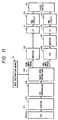
- Fig. 8 is a block diagram which illustrates a signal processing operation for forming a digital full color image performed by the image forming apparatus according to the third embodiment of the present invention.
- reference numeral 110 represents a CCD and 102 represents a shading correction circuit for correcting scatter in the R (red), G (green) and B (blue) image brightness signals read by the CCD 101 between the light receipt cells of the CCD.
- Reference numeral 103 represents a LOG conversion circuit for converting the RBG brightness signals into C (cyan), M (magenta) and Y (yellow) image density signals.
- Reference numeral 104 represents an image separation circuit for selecting an image processing series in accordance with a tone image, which has been previously designated by a digitizer (area designation means) 121, and a region of a line image.
- Reference numeral 105 represents a masking processing circuit or color-correcting the tone image signal in accordance with the output characteristics of the printer.
- Reference numeral 106 represents a UCR circuit for generating a BK (black) signal from the C, M and Y line image signals.
- Reference numeral 107 represents a masking processing circuit for color-correcting the line image signal by using a masking coefficient which is different from that for use in the masking processing circuit 105.
- Reference numeral 108 represents an LUT for correcting the tone image signal and the line image signal in accordance with the tone characteristics of the printer.
- Reference numeral 109 represents a PWM (Pulse Width Modulation) circuit for converting the pulse width of the signal to correspond to the image density for the purpose of obtaining a tone image of an area tone type.
- Reference numeral 120 represents a laser driver for driving a laser in response to a pulse width signal supplied from the PWM 109 so as to form a latent image on the surface of the photosensitive member. The formed latent image is developed by using a toner so that a visible image is formed.
- the CCD 101, the shading correction circuit 102, the LOG conversion circuit 103, the PWM circuit 109 and the laser driver 120 are the same as those according to the structure shown in Fig. 3.
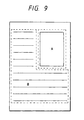
- the digitizer for use in a conventional copying machine acts to designate region A of the original document as a tone image region as shown in Fig. 9, while region B of the same is designated by a user as the line image region for characters or the like.
- the R, G and B image brightness signals read by the CCD 101 are subjected by a process in which scatter between the light receiving cells of the CCD 101 is corrected by the shading correction circuit 102. Then, the RGB brightness signals are converted into C, M and Y image density signals by the LOG conversion circuit 103. Then, the image separation circuit 104 selects the image processing series in accordance with the predetermined tone image and the line image region.
- the region designated as the tone region is arranged in such a manner that the rate of black color generation is made to be 0%, that is, the same is not subjected to the UCR (Under Color Removal) but the same is color-corrected by the masking processing circuit 105.
- the region designated as the line image region is arranged in such a manner that the rate of black color generation (the quantity of under color removal) is made to be 100% by the UCR circuit 106 before it is color-corrected by the masking processing circuit 107.
- both of the tone image signal and the line image signal are corrected so as to adapt to the tone characteristics of the printer by the LUT 108. Then, the same are converted into the pulse width signals which correspond to the image density for the purpose of obtaining a tone image in an area tone manner by the PWM 109.
- the laser driver 120 drives the laser source. Laser beams emitted from the laser source are used to scan the surface of the photosensitive drum so that a latent image is formed. Then, the latent images are developed by the corresponding color toners in accordance with a conventional electrophotography process. The color toner images are transferred to the surface of the recording medium in a multiplied manner before the transferred images are fixed so that a full color image is formed.
- the tone image region A was formed by the cyan, magenta and yellow toners each having substantially the same softening point. Therefore, the glossiness of the region A was made to be uniform.
- the line image region B including characters was formed by four color toners including the black toner the softening point of which is higher than the color toners by 10°C or more. In particular, the glossiness of the black characters are reduced so that the characters could be easily read.
- the image in the toner image region may be subjected to the UCR process in which the rate of black color generation is reduced similarly to the first embodiment so as to change the glossiness.
- a fifth embodiment of the present invention is different from the fourth embodiment in the method of discriminating the image region. That is, although the same if discriminated by user according to the fourth embodiment, this embodiment is arranged in such a manner that the same is discriminated automatically.
- the character/line images and the tone images are separated from one another by comparing the pixel patterns. That is,
- the image separation is arranged to be automatically discriminated, the labor of a user can be reduced. Furthermore, the tone image displayed uniform glossiness and the glossiness of the black characters could be reduced among the characters of the character/line image. As a result, an image displaying excellent quality could be obtained.
- Another structure may be employed which is arranged in such a manner that the image region separation in accordance with the user designation according to the fourth embodiment is also employed so as to be used when it is manually designated although the automatic discrimination is usually performed.
- the image separation method is not limited to the above-described example and another conventional method may be employed.
- Fig. 11 illustrates a sixth embodiment of the present invention.
- This embodiment is different from the fourth embodiment in the process to be performed after the image separation.
- the CCD 101 reads the image at 400 dpi (dot per inch) and the resolution of the region, which has been discriminate as the tone image, is raised to a high tone of 200 dpi.
- the tone image signal in this case is transmitted to a laser drive 155 via the masking processing circuit 105, the LUT 151 and a PWM circuit 153.
- the resolution of the region which has been discriminated as the line image is set to a high resolution of 400 dpi.
- the line image signal is transmitted to the laser driver 155 via the UCR 106, the masking processing circuit 107, the LUT 152 and the PWM circuit 154.
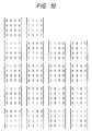
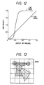
- the LUT 152 is set as designated as the tone characteristics shown in Fig. 12 in which the line image forms an S-curve.
- the resolution is changed for the tone image and for the line image and as well as the tone characteristics are changed so that the tone image displayed a smooth gradation and uniform glossiness.
- the line image can be formed while exhibiting an excellent contrast of the fine portions, high resolution and reduced glossiness. Therefore, the overall image quality can be significantly improved.
- the fourth embodiment may be arranged in such a manner that the tone image and the line image can be automatically discriminated from each other similarly to the fifth embodiment.
- This embodiment is different from the second embodiment in that the method of controlling the rate of black color generation. That is, according to this embodiment, an image is divided into, for example, 25 regions as shown in Fig. 13 and the glossiness of the image in each region is detected so that the rate of black color generation suitable for each region is selected. The glossiness of the image is detected by using a glossiness measuring circuit 191 as shown in Fig. 14. The glossiness measuring circuit 191 measures the glossiness of the image in each region by dividing the image signals for one line into regions and by using the image signal for a predetermined number of lines. The UCR circuit 106 determines the rate of black color generation for each region in accordance with the relationship between the rate of black color generation and the glossiness of the output image as shown in Fig. 5.
- glossiness further like that of the original document can be obtained and thereby an image exhibiting further excellent quality can be obtained.
- the glossiness for each region may be selected by a user similarly to the fourth embodiment.
- the region selection can, of course, be made variously in place of the above-described example.
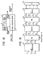
- Fig. 15 illustrates the basic structure of an eighth embodiment of the present invention.
- symbol A represents a signal processing means for changing the calculating algorithm for converting an input image signal into recording signals of each hue in accordance with the designation signal denoting the characteristics or kind of the recording medium.
- the signal processing means A varies the forming condition of a black recording signal in response to, for example, a designation signal.
- the above-described designation signal denotes, for example, whether or not the recording medium is transparent so that the signal processing means A varies the recording signal forming condition in accordance with whether or not the recording medium is transparent.
- the designation signal designates the optical characteristics of the recording medium including information about the smoothness of the surface of the recording medium.
- the above-described designation signal is a detection signal of a detection means B which detects the characteristics or the kind of the recording medium or a signal of an input means C which designates and receives the characteristics or the kind of the recording medium.
- Fig. 16 illustrates the structure of an image processing circuit for converting R (red), G (green) and B (blue) signals into C, M, Y and BK recording signals, the R (red), G (green) and B (blue) signals being image information items about the original document read by the image sensor (for example, a photoelectrical conversion device such as a CCD sensor array) of the reading portion (image reading portion) 11 shown in Fig. 2.
- the image sensor for example, a photoelectrical conversion device such as a CCD sensor array
- R, G and B input image signals are converted into C 0 , M 0 and Y 0 density signals by a CMY conversion circuit 131.
- the density signals are supplied to a UCR (Under Color Removal) calculator 132 in which the density (the output level) of the BK signal is determined in accordance with a signal having the lowest density level among the C 0 , M 0 and Y 0 density signals and a medium signal PS to be described later.
- UCR Under Color Removal
- output signals C 1 , M 1 , Y 1 and BK 1 from the UCR calculator 32 are subjected to a predetermined masking process in a masking circuit 133 before a pulse width modulation process is performed in a PWM (Pulse Width Modulation) circuit 134.
- An output signal from the PWM circuit 34 is supplied to an LD driver 135 so that the laser diode (LD) 136 is driven.
- Fig. 17 illustrates the characteristics of the calculating algorithm of the UCR calculator 132. That is, referring to Fig. 17, curve A shows the characteristic value which is selected in a case of an opaque medium such as ordinary wood free paper.
- the axis of abscissa stands for the level of a signal the density level of which is the lowest in a case where the density of the cyan, magenta, yellow density signals C 0 , M 0 and Y 0 is expressed by 255 levels (gradation).
- the axis of ordinate stands for the density level of the BK (black) signal which is generated at the above-described case.
- curve B shows the characteristics value which is selected when an image is formed on a transparent recording medium, for example, a OHP sheet. The density level of the signal is lowered in comparison to that shown by the curve A.
- the C, M and Y toners for use in the developing device 3 comprise a two-component developer and BK toner comprises a single component developer composed of a magnetic toner. Therefore, since the BK toner has insufficient transparency, the quantity of the BK toner must be considerably reduced in a case where an image is formed on the OHP sheet in comparison to a case where an image is formed on plain paper. The reason for this lies in that the image formed by the BK toner display a small quantity of transmissive light.
- the UCR calculator 132 performs the UCR calculation of the output characteristics as shown in Fig. 17 in response to the medium signal PS.
- data as shown in Fig. 17 is previously stored in an internal memory (omitted from illustration) of the UCR calculator 132.
- a black data signal BK 1 is transmitted from the internal memory (look-up memory) in response to the medium signal PS and in accordance with the minimum value of the density signals C 0 , M 0 and Y 0 .
- a signal exhibiting excellent quality is also obtained by arranging the structure in such a manner that the UCR calculator 132 shown in Fig. 16 does not transmit the BK signal in a case where a transparent recording medium is used.
- Another structure may be employed which is arranged in such a manner that a conventional black character extraction circuit (omitted from illustration) is connected between the CMY conversion circuit 131 and the UCR calculator 132 shown in Fig. 16 and the black character extraction circuit recognizes a black character region so as to transmit the BK signal denoting only the recognized black character portion. Also in this case, an image exhibiting further high quality can be obtained.
- a structure is employed in which a manipulation button (omitted from illustration) for selecting and designating the surface smoothness of the recording medium is provided on the manipulating panel (omitted from illustration) of the copying machine.
- the characteristics of the curve B shown in Fig. 17 are selected by the UCR calculator 132 in a case where the recording medium has a high surface smoothness so that the BK toner displaying insufficient transparency is not used as possible. As a result, an image exhibiting excellent quality can be formed.
- Fig. 18 illustrates the structure of an essential portion of a thermal transfer recording apparatus.
- a roll paper shape recording medium 151 is supplied between a thermal head 152 and a confronting roll 153 so that a coloring material of a color thermal transfer ribbon 154 is transferred to the recording medium 151 before it is cut into a sheet shape.
- the BK (black) coloring material has bad transparency. Therefore, the above-described UCR calculation is performed by the UCR calculator 132 so that an image exhibiting excellent quality is obtained.
- the present invention is not limited to this.
- Another structure may be employed in which the calculating algorithm for the masking operation is also changed in addition to the change of the calculating algorithm of the UCR to adapt to the transparency of the C, M and Y coloring materials or the optical characteristics of the recording medium, resulting an improvement in the image quality.
- a similar effect can be obtained by changing the scanning density on the calculating algorithm in a case of an apparatus in which an optical scan is performed by using laser beams.
- the present invention may, of course, be adapted not only to the recording apparatus but also to a display apparatus which uses a coloring agent such as the electrophotographic display apparatus.
- a structure be employed in which a plurality of characteristics corresponding to the curve B shown in Fig. 17 are provided so as to be arbitrarily selected through a manipulating button. In this case, an image output of a desired color by a user can be obtained.
- the recording medium is not limited to the OHP film but a semitransparent back print film or the like may be employed to obtain a similar effect.
- the color development order in each of the above-described embodiments will not be described.
- the quality of the image will be deteriorated if the image is formed in such a manner that the black toner having low glossiness is positioned at the uppermost layer. Accordingly, the black toner is arranged to be positioned at the lowest layer in order to improve the quality of the formed image. Then, an embodiment arranged in this manner will now be described.
- this embodiment is arranged in such a manner that an image carrier 1001 serving as an electrophotography photosensitive drum is held in such a manner than it can be rotated in a direction as designated by an arrow. The same is uniformly charged by a charger 1002 before an optical image is irradiated on the photosensitive drum 1001 by a laser beam exposure means 1003 so that an electrostatic latent image is formed.
- the exposure means 1003 receives CMYBK color decomposition density signals, which are the output signals from a color image input apparatus and a color image processing apparatus (omitted from illustration).
- CMYBK digital image signals are respectively digital/analog converted by a D/A converter 1101 before the same is voltage/time converted by a V/T converter 1102. Then, it is supplied to a laser driver 1103.
- the laser emitting time is adjusted in response to the image signal and the electrostatic latent images corresponding to the image signals are formed on the photosensitive drum 1001 by a laser scanning optical system comprising a collimator lens and a rotational polygonal mirror 1104.
- the latent image thus formed is developed and made to be a visible image by an arbitrary developing device, a yellow developing device 1004Y in a case shown in Fig. 19, selected from four developing devices fastented to a rotational developing devices, that is, a yellow developing device 1004Y, a magenta developing device 1004M, a cyan developing device 1004C and a black developing device 1004Bk.
- the visible image (toner image) thus-developed is, by a transfer charger 1006, transferred to recording paper P which is electrostatically absorbed onto a transfer drum 1005.
- the photosensitive drum 1001 is subjected to a residual toner removal operation performed by a cleaning means 1010 before it is subjected to a next image forming process.
- toner images are formed on the photosensitive drum 1001 so that the second, the third and the fourth toner images are transferred onto the same recording paper P in a layered manner.
- the recording paper P on which the same are formed in the layered manner is separated from the transfer drum 1005 by a separation charger 1007 before it is discharged outside the apparatus via a fixing device (omitted from illustration).
- the above-described color image forming process is sequentially performed starting from the color which displays the lowest surface glossiness when an image is formed by the same quantity. That is, assuming that the black (Bk), the cyan (C), the magenta (M) and yellow (Y) toners have lower glossiness in this sequential order, the rotational developing device 1004 is, as shown in Fig. 19, arranged in such a manner that the black developing device 1004Bk, the cyan developing device 1004C, the magenta developing device 1004M and the yellow developing device 1004Y are disposed in a direction of rotation.
- the black (Bk) latent image is commenced on the photosensitive drum 1001 before the cyan (C), magenta (M) and yellow (Y) latent images are sequentially formed. Also in a case of a horizontally moving type developing device, the black developing device, the cyan developing device, the magenta developing device and the yellow developing device are arranged in this order.
- JIS Japanese Industrial Standard
- Z8741 60° method
- Figs. 20A illustrates a state in which images (toner images) thus-formed are color-mixed.
- Fig. 20B microscopically illustrates the state in which the toners are color-mixed when an achromatic color (gray) is reproduced.
- the achromatic color is reproduced by mixing a black toner and a little quantity of CMY toners in such a manner that black color is generated and the under color is removed by the skeleton black method.
- the same color is reproduced by mixing the cyan (C), the magenta (M), the yellow (Y) and the black (Bk) toners.
- the yellow (Y), the magenta (M), the cyan (C) and the black (Bk) toners are layered in this sequential order from the lowest layer of the drawing sheet.
- the black toner (Bk) is placed at the lower layer and the other toners are layered on it.
- the black (Bk) toner is present on the surface of the image because it is not sufficiently dissolved after the fixing process has been completed. Therefore, small uneven portions are formed on the surface of the image, causing light made incident upon the surface of the image to be diffused and thereby the glossiness to be lowered.
- the black (Bk) toner is disposed in the lower layer and the other color toners are layered on it. Furthermore, the color toner layers are formed on the fixed black toner. Therefore, the surface of the image can be made to be smooth, causing the glossiness of the surface of the formed image to be the same as the glossiness realized by a single color toner.
- the image forming test was performed by using a developer prepared by mixing the above-described four kinds of the toners with magnetic carrier particles.
- Fig. 21 illustrates a color image forming apparatus arranged in accordance with a plural drum system according to another embodiment of the present invention.
- photosensitive drums 2001 (2001BK, 2001C, 2001M and 2001Y) comprising image carriers are disposed to the corresponding color image forming processes.
- chargers 2002 (2002BK, 2002C, 2002M and 2002Y), laser beam exposure means 2003 (2003BK, 2003C, 2003M and 2003Y) and developing devices 2004 (2004BK, 2004C, 2004M and 2004Y) are disposed around the photosensitive drum 2001 so that color images are formed.
- the color images formed on the photosensitive drums 2001BK, 2001C, 2001M and 2001Y are transferred to recording paper P which is conveyed by a transfer belt 2005 before they are fixed by a fixing device 2011 and then the recording paper P is discharged outside from the apparatus.
- the residual toners on the photosensitive drums 2001 (2001B, 2001C, 2001M and 2001Y) are removed by cleaning means 2010 (2010BK, 2010C, 2010M and 2010Y).
- the image forming is commenced from the black (BK) toner having the lowest glossiness before the cyan (C), the magenta (M) and the yellow (Y) toner images are sequentially formed.
- BK black
- M magenta
- Y yellow
- a magnetic toner containing a magnetic material such as magnetite in its toner binder may be used.
- magnetite is an insoluble material, a high melting point is usually displayed by the magnetic toner containing it. Furthermore, magnetite powder forms fine uneven portions on the fixed image, the glossiness of the surface of the formed image is significantly reduced because incidental light is easily diffused and reflected. Therefore, a further significant effect can be obtained in a case where the present invention is adapted to the magnetic toner.
- an image exhibiting excellent quality can be formed by the jumping development method which uses a single magnetic component while using a toner composed of 100 parts by weight of main binder of a polyester type the number average molecular weight of which is about 3500, 60 parts by weight of magnetite, 2 parts by weight of the CA agent and an additive.
Claims (7)
- Farbbildverarbeitungsgerät, mitgekennzeichnet durcheiner Eingabeeinrichtung (21) zum Eingeben einer Vielzahl von Farbkomponentensignalen,einer ersten Entwicklungseinrichtung (3Y, 3M, 3C) mit einem ersten Entwickler,einer zweiten Entwicklungseinrichtung (3Bk) mit einem zweiten Entwickler, dessen Glanz von dem des ersten Entwicklers verschieden ist, undeiner Unterfarbenentfernungsverarbeitungseinrichtung (24) zum Entfernen einer Unterfarbe, die in der Vielzahl der von der Eingabeeinrichtung zugeführten Farbkomponentensignale vorhanden ist, wobei die so korrigierte Vielzahl von Farbkomponenten verwendet wird, um die chromatische Komponente eines Ausgabebilds unter Verwendung der ersten Entwicklungseinrichtung zu erzeugen, und wobei die Menge der entfernten Unterfarbe verwendet wird, um die achromatische Komponente des Ausgabebilds mittels des zweiten Entwicklers zu erzeugen,eine Steuereinrichtung (CPU) zum Verändern des Glanzes des Ausgabebilds durch Steuern der relativen Menge der durch die Unterfarbenentfernungsverarbeitungseinrichtung entfernten Unterfarbe.
- Farbbildverarbeitungsgerät nach Anspruch 1, wobei die Unterfarbenentfernungsverarbeitungseinrichtung die Unterfarbe in Übereinstimmung mit der Dichte jedes einer Vielzahl der Farbkomponentensignale verarbeitet.
- Farbbildverarbeitungsgerät nach Anspruch 2, wobei die Unterfarbenentfernungsverarbeitungseinrichtung einen Teil einer Vielzahl der Farbkomponentensignale durch ein anderes Farbkomponentensignal ersetzt.
- Farbbildverarbeitungseinrichtung nach Anspruch 1, wobei eine Vielzahl der Farbkomponentensignale Bildsignale sind, die Farbkomponenten von magenta, cyan und gelb jeweils wiedergeben, und wobei die Unterfarbenentfernungsverarbeitungseinrichtung ein eine schwarze Farbkomponente wiedergebendes Bildsignal von den die Farbkomponenten magenta, cyan und gelb wiedergebenden Bildsignalen extrahiert und die Bildsignale jeder Farbkomponente magenta, cyan und gelb herausgibt, nachdem das Bildsignal der schwarzen Farbkomponente extrahiert ist.
- Farbbildverarbeitungsgerät nach Anspruch 4, ferner mit entsprechenden Entwicklungseinrichtungen (3) für magenta, cyan, gelb und schwarz Farbmittel, wobei das schwarze Farbmittel einen Glanz hat, der geringer ist, als der jedes der magenta, cyan, gelb Farbmittel, und
einer Bilderzeugungseinrichtung (4) zur Erzeugung von Farbbildern mittels einer Vielzahl der Entwicklungseinrichtungen in Übereinstimmung mit den Bildsignalen, die jeweils die magenta, cyan, gelb und schwarz Farbkomponenten wiedergeben und von der Unterfarbenverarbeitungseinrichtung übertragen sind. - Farbbilderzeugungsgerät nach Anspruch 5, wobei die magenta, cyan und gelb Farbmittel Toner sind, welche jeweils einen Schmelzpunkt haben, der niedriger ist als der des schwarzen Farbmittels.
- Farbbilderzeugungsgerät nach Anspruch 5, wobei das schwarze Farbmittel ein magnetischer Toner ist.
Applications Claiming Priority (8)
| Application Number | Priority Date | Filing Date | Title |
|---|---|---|---|
| JP329730/90 | 1990-11-30 | ||
| JP329731/90 | 1990-11-30 | ||
| JP329729/90 | 1990-11-30 | ||
| JP32973190A JP3168001B2 (ja) | 1990-11-30 | 1990-11-30 | カラー画像処理装置 |
| JP2329730A JPH04207463A (ja) | 1990-11-30 | 1990-11-30 | 画像形成装置 |
| JP2329729A JPH04204566A (ja) | 1990-11-30 | 1990-11-30 | カラー画像形成方法及び装置 |
| JP31179691 | 1991-10-30 | ||
| JP311796/91 | 1991-10-30 |
Publications (3)
| Publication Number | Publication Date |
|---|---|
| EP0488412A2 EP0488412A2 (de) | 1992-06-03 |
| EP0488412A3 EP0488412A3 (en) | 1992-10-21 |
| EP0488412B1 true EP0488412B1 (de) | 1998-08-26 |
Family
ID=27480056
Family Applications (1)
| Application Number | Title | Priority Date | Filing Date |
|---|---|---|---|
| EP91120617A Expired - Lifetime EP0488412B1 (de) | 1990-11-30 | 1991-11-29 | Gerät zur Erzeugung von Farbbildern |
Country Status (3)
| Country | Link |
|---|---|
| US (1) | US5162860A (de) |
| EP (1) | EP0488412B1 (de) |
| DE (1) | DE69130053T2 (de) |
Families Citing this family (23)
| Publication number | Priority date | Publication date | Assignee | Title |
|---|---|---|---|---|
| JPH06121161A (ja) * | 1991-05-14 | 1994-04-28 | Fuji Xerox Co Ltd | カラー画像処理装置の文字処理方式 |
| DE69311930T2 (de) * | 1992-01-31 | 1997-11-20 | Canon Kk | Flüssigkristall-Lichtventil mit aktiver Matrix und Treiberschaltung |
| JP3332459B2 (ja) * | 1993-04-09 | 2002-10-07 | キヤノン株式会社 | カラー画像処理装置およびカラー画像処理方法 |
| JPH08202199A (ja) * | 1995-01-23 | 1996-08-09 | Canon Inc | 画像形成装置 |
| JPH09116771A (ja) * | 1995-10-18 | 1997-05-02 | Mita Ind Co Ltd | カラー画像生成機 |
| US5748221A (en) * | 1995-11-01 | 1998-05-05 | Xerox Corporation | Apparatus for colorimetry gloss and registration feedback in a color printing machine |
| US5859928A (en) * | 1996-06-21 | 1999-01-12 | Hewlett-Packard Company | Jitter-form background control for minimizing spurious gray cast in scanned images |
| US5716750A (en) * | 1996-06-28 | 1998-02-10 | Eastman Kodak Company | Method and apparatus for controlling gloss for toner images |
| DE69738923D1 (de) * | 1997-03-14 | 2008-10-02 | Punch Graphix Int Nv | Verfahren zur Steuerung des Glanzes in einem elektrographischem Gerät |
| JP2000036907A (ja) * | 1998-07-17 | 2000-02-02 | Minolta Co Ltd | 画像読取装置 |
| US6483606B1 (en) * | 1998-08-26 | 2002-11-19 | Xerox Corporation | Error diffusion on moderate numbers of output colors |
| WO2000060848A1 (fr) * | 1999-03-30 | 2000-10-12 | Matsushita Electric Industrial Co., Ltd. | Procede de correction de couleurs de dispositif de production d'image |
| US6498910B2 (en) * | 2000-04-07 | 2002-12-24 | Konica Corporation | Image forming with light and dark hue toners |
| US7087305B2 (en) * | 2002-05-30 | 2006-08-08 | Eastman Kodak Company | Fuser member with tunable gloss level and methods and apparatus for using the same to fuse toner images |
| JP3941804B2 (ja) * | 2004-07-27 | 2007-07-04 | ブラザー工業株式会社 | 画像処理方法 |
| JP4306557B2 (ja) * | 2004-08-05 | 2009-08-05 | コニカミノルタビジネステクノロジーズ株式会社 | 画像形成システム |
| JP4583887B2 (ja) * | 2004-11-11 | 2010-11-17 | 株式会社リコー | 画像処理方法、プリンタドライバ、画像形成装置、画像処理装置及び画像形成システム |
| JP2007307885A (ja) * | 2005-11-04 | 2007-11-29 | Ricoh Co Ltd | 画像処理方法、記録物、プログラム、画像処理装置、画像形成装置及び画像形成システム、画像形成方法及びインク |
| US8203754B2 (en) * | 2007-10-01 | 2012-06-19 | Brother Kogyo Kabushiki Kaisha | Color conversion device, program, and method |
| JP2009117992A (ja) * | 2007-11-02 | 2009-05-28 | Fujifilm Corp | 画像データ修正装置および画像データ修正プログラム |
| JP5237205B2 (ja) * | 2009-06-17 | 2013-07-17 | キヤノン株式会社 | 画像処理装置およびその制御方法 |
| JP2012186770A (ja) * | 2011-03-08 | 2012-09-27 | Fuji Xerox Co Ltd | 画像処理装置、画像形成装置、及びプログラム |
| JP6194660B2 (ja) * | 2012-09-28 | 2017-09-13 | 三菱ケミカル株式会社 | 画像形成方法及び画像形成装置 |
Family Cites Families (7)
| Publication number | Priority date | Publication date | Assignee | Title |
|---|---|---|---|---|
| JPS57173859A (en) * | 1981-04-20 | 1982-10-26 | Canon Inc | Exposure quantity controller of color picture forming device |
| US4578331A (en) * | 1983-07-11 | 1986-03-25 | Ricoh Company, Ltd. | Color image forming method |
| JPS60260969A (ja) * | 1984-06-08 | 1985-12-24 | Fuji Xerox Co Ltd | 多色画像記録装置 |
| JPS63173646A (ja) * | 1987-01-13 | 1988-07-18 | Ricoh Co Ltd | 画像形成装置 |
| JPH01142740A (ja) * | 1987-11-30 | 1989-06-05 | Konica Corp | カラー画像形成装置 |
| US5030539A (en) * | 1988-02-29 | 1991-07-09 | The Mead Corporation | Developer sheet useful in providing transparencies or reproductions having a controlled gloss finish utilizing a surfactant |
| JP2768983B2 (ja) * | 1989-06-26 | 1998-06-25 | 株式会社リコー | カラー画像処理装置 |
-
1991
- 1991-11-27 US US07/799,333 patent/US5162860A/en not_active Expired - Lifetime
- 1991-11-29 EP EP91120617A patent/EP0488412B1/de not_active Expired - Lifetime
- 1991-11-29 DE DE69130053T patent/DE69130053T2/de not_active Expired - Lifetime
Also Published As
| Publication number | Publication date |
|---|---|
| DE69130053D1 (de) | 1998-10-01 |
| EP0488412A3 (en) | 1992-10-21 |
| EP0488412A2 (de) | 1992-06-03 |
| US5162860A (en) | 1992-11-10 |
| DE69130053T2 (de) | 1999-03-25 |
Similar Documents
| Publication | Publication Date | Title |
|---|---|---|
| EP0488412B1 (de) | Gerät zur Erzeugung von Farbbildern | |
| US5258783A (en) | Image processing method and apparatus with gamma-correction control | |
| US5200817A (en) | Conversion of an RGB color scanner into a colorimetric scanner | |
| JPH01309467A (ja) | 画像処理装置 | |
| US5157483A (en) | Multicolor image forming method and apparatus | |
| JP4146987B2 (ja) | 画像形成装置 | |
| JPH0983827A (ja) | カラー画像調整装置およびカラー画像調整方法 | |
| JP4228620B2 (ja) | 画像形成装置 | |
| US5557428A (en) | Color image forming apparatus which changes color image processing based on properties of a recording medium | |
| US7044364B2 (en) | Image forming apparatus and image forming method | |
| JPH0662249A (ja) | カラー画像記録装置 | |
| JP3168001B2 (ja) | カラー画像処理装置 | |
| JP2755972B2 (ja) | カラー画像処理装置 | |
| JPH089154A (ja) | 画像処理装置 | |
| JPH10210314A (ja) | ディジタル画像処理装置 | |
| JP3320093B2 (ja) | 画像処理装置及び画像処理方法 | |
| JPH0628277Y2 (ja) | カラ−画像出力装置 | |
| JPH02144566A (ja) | カラー画像処理装置 | |
| JP2006080834A (ja) | 画像形成装置 | |
| JP3177977B2 (ja) | カラー複写機及び画像処理装置 | |
| JPH02281877A (ja) | 多色画情報生成装置及びこれを用いた画像処理装置 | |
| JPH01184136A (ja) | 画像出力装置におけるスクリーン角度設定方法および装置 | |
| JPH02144568A (ja) | カラー画像処理装置 | |
| JP2002091120A (ja) | カラー画像形成装置 | |
| JPH02170694A (ja) | カラー画像処理装置 |
Legal Events
| Date | Code | Title | Description |
|---|---|---|---|
| PUAI | Public reference made under article 153(3) epc to a published international application that has entered the european phase |
Free format text: ORIGINAL CODE: 0009012 |
|
| AK | Designated contracting states |
Kind code of ref document: A2 Designated state(s): DE FR GB IT |
|
| PUAL | Search report despatched |
Free format text: ORIGINAL CODE: 0009013 |
|
| AK | Designated contracting states |
Kind code of ref document: A3 Designated state(s): DE FR GB IT |
|
| 17P | Request for examination filed |
Effective date: 19930308 |
|
| 17Q | First examination report despatched |
Effective date: 19951120 |
|
| GRAG | Despatch of communication of intention to grant |
Free format text: ORIGINAL CODE: EPIDOS AGRA |
|
| GRAG | Despatch of communication of intention to grant |
Free format text: ORIGINAL CODE: EPIDOS AGRA |
|
| GRAH | Despatch of communication of intention to grant a patent |
Free format text: ORIGINAL CODE: EPIDOS IGRA |
|
| GRAH | Despatch of communication of intention to grant a patent |
Free format text: ORIGINAL CODE: EPIDOS IGRA |
|
| GRAA | (expected) grant |
Free format text: ORIGINAL CODE: 0009210 |
|
| AK | Designated contracting states |
Kind code of ref document: B1 Designated state(s): DE FR GB IT |
|
| PG25 | Lapsed in a contracting state [announced via postgrant information from national office to epo] |
Ref country code: IT Free format text: LAPSE BECAUSE OF FAILURE TO SUBMIT A TRANSLATION OF THE DESCRIPTION OR TO PAY THE FEE WITHIN THE PRESCRIBED TIME-LIMIT;WARNING: LAPSES OF ITALIAN PATENTS WITH EFFECTIVE DATE BEFORE 2007 MAY HAVE OCCURRED AT ANY TIME BEFORE 2007. THE CORRECT EFFECTIVE DATE MAY BE DIFFERENT FROM THE ONE RECORDED. Effective date: 19980826 Ref country code: FR Free format text: LAPSE BECAUSE OF FAILURE TO SUBMIT A TRANSLATION OF THE DESCRIPTION OR TO PAY THE FEE WITHIN THE PRESCRIBED TIME-LIMIT Effective date: 19980826 |
|
| REF | Corresponds to: |
Ref document number: 69130053 Country of ref document: DE Date of ref document: 19981001 |
|
| PG25 | Lapsed in a contracting state [announced via postgrant information from national office to epo] |
Ref country code: GB Free format text: LAPSE BECAUSE OF NON-PAYMENT OF DUE FEES Effective date: 19981129 |
|
| EN | Fr: translation not filed | ||
| PLBE | No opposition filed within time limit |
Free format text: ORIGINAL CODE: 0009261 |
|
| STAA | Information on the status of an ep patent application or granted ep patent |
Free format text: STATUS: NO OPPOSITION FILED WITHIN TIME LIMIT |
|
| GBPC | Gb: european patent ceased through non-payment of renewal fee |
Effective date: 19981129 |
|
| 26N | No opposition filed | ||
| PGFP | Annual fee paid to national office [announced via postgrant information from national office to epo] |
Ref country code: DE Payment date: 20091130 Year of fee payment: 19 |
|
| REG | Reference to a national code |
Ref country code: DE Ref legal event code: R119 Ref document number: 69130053 Country of ref document: DE Effective date: 20110601 Ref country code: DE Ref legal event code: R119 Ref document number: 69130053 Country of ref document: DE Effective date: 20110531 |
|
| PG25 | Lapsed in a contracting state [announced via postgrant information from national office to epo] |
Ref country code: DE Free format text: LAPSE BECAUSE OF NON-PAYMENT OF DUE FEES Effective date: 20110531 |