EP0485461B1 - Senkrechtes wärmereaktorsystem - Google Patents
Senkrechtes wärmereaktorsystem Download PDFInfo
- Publication number
- EP0485461B1 EP0485461B1 EP90911896A EP90911896A EP0485461B1 EP 0485461 B1 EP0485461 B1 EP 0485461B1 EP 90911896 A EP90911896 A EP 90911896A EP 90911896 A EP90911896 A EP 90911896A EP 0485461 B1 EP0485461 B1 EP 0485461B1
- Authority
- EP
- European Patent Office
- Prior art keywords
- chamber
- reactor system
- wafers
- boat
- opening
- Prior art date
- Legal status (The legal status is an assumption and is not a legal conclusion. Google has not performed a legal analysis and makes no representation as to the accuracy of the status listed.)
- Expired - Lifetime
Links
Images





Classifications
-
- H—ELECTRICITY
- H10—SEMICONDUCTOR DEVICES; ELECTRIC SOLID-STATE DEVICES NOT OTHERWISE PROVIDED FOR
- H10P—GENERIC PROCESSES OR APPARATUS FOR THE MANUFACTURE OR TREATMENT OF DEVICES COVERED BY CLASS H10
- H10P72/00—Handling or holding of wafers, substrates or devices during manufacture or treatment thereof
- H10P72/04—Apparatus for manufacture or treatment
- H10P72/0431—Apparatus for thermal treatment
- H10P72/0436—Apparatus for thermal treatment mainly by radiation
-
- F—MECHANICAL ENGINEERING; LIGHTING; HEATING; WEAPONS; BLASTING
- F27—FURNACES; KILNS; OVENS; RETORTS
- F27B—FURNACES, KILNS, OVENS OR RETORTS IN GENERAL; OPEN SINTERING OR LIKE APPARATUS
- F27B17/00—Furnaces of a kind not covered by any of groups F27B1/00 - F27B15/00
- F27B17/0016—Chamber type furnaces
- F27B17/0025—Chamber type furnaces specially adapted for treating semiconductor wafers
-
- H—ELECTRICITY
- H10—SEMICONDUCTOR DEVICES; ELECTRIC SOLID-STATE DEVICES NOT OTHERWISE PROVIDED FOR
- H10P—GENERIC PROCESSES OR APPARATUS FOR THE MANUFACTURE OR TREATMENT OF DEVICES COVERED BY CLASS H10
- H10P72/00—Handling or holding of wafers, substrates or devices during manufacture or treatment thereof
- H10P72/30—Handling or holding of wafers, substrates or devices during manufacture or treatment thereof for conveying, e.g. between different workstations
- H10P72/34—Handling or holding of wafers, substrates or devices during manufacture or treatment thereof for conveying, e.g. between different workstations the wafers being stored in a carrier, involving loading and unloading
- H10P72/3404—Storage means
-
- H—ELECTRICITY
- H10—SEMICONDUCTOR DEVICES; ELECTRIC SOLID-STATE DEVICES NOT OTHERWISE PROVIDED FOR
- H10P—GENERIC PROCESSES OR APPARATUS FOR THE MANUFACTURE OR TREATMENT OF DEVICES COVERED BY CLASS H10
- H10P72/00—Handling or holding of wafers, substrates or devices during manufacture or treatment thereof
- H10P72/30—Handling or holding of wafers, substrates or devices during manufacture or treatment thereof for conveying, e.g. between different workstations
- H10P72/34—Handling or holding of wafers, substrates or devices during manufacture or treatment thereof for conveying, e.g. between different workstations the wafers being stored in a carrier, involving loading and unloading
- H10P72/3411—Handling or holding of wafers, substrates or devices during manufacture or treatment thereof for conveying, e.g. between different workstations the wafers being stored in a carrier, involving loading and unloading involving loading and unloading of wafers
-
- Y—GENERAL TAGGING OF NEW TECHNOLOGICAL DEVELOPMENTS; GENERAL TAGGING OF CROSS-SECTIONAL TECHNOLOGIES SPANNING OVER SEVERAL SECTIONS OF THE IPC; TECHNICAL SUBJECTS COVERED BY FORMER USPC CROSS-REFERENCE ART COLLECTIONS [XRACs] AND DIGESTS
- Y10—TECHNICAL SUBJECTS COVERED BY FORMER USPC
- Y10S—TECHNICAL SUBJECTS COVERED BY FORMER USPC CROSS-REFERENCE ART COLLECTIONS [XRACs] AND DIGESTS
- Y10S414/00—Material or article handling
- Y10S414/135—Associated with semiconductor wafer handling
- Y10S414/137—Associated with semiconductor wafer handling including means for charging or discharging wafer cassette
Definitions
- the present invention relates to an enhanced vertical thermal reactor system for use in the processing of semiconductor wafers and the like.
- a thermal reactor system characterized by a vertical thermal reactor system characterized by a wafer handling chamber into which semicondconductor wafers are placed into the reactor system for processing and from which processed wafers are removed from the reactor system, said wafer handling chamber including a carousel for holding a plurality of wafers before and after processing;
- Fig. 1 depicts a plan view of an enhanced vertical thermal reactor system according to the present invention.
- Fig. 2 depicts a diagram illustrating the operation of the system of Fig. 1.
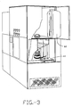
- Fig. 3 depicts a rear access view of the system according to the present invention.
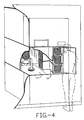
- Fig. 4 depicts a wafer handler view according to the present invention.
- Fig. 5 depicts a front view of the present invention.
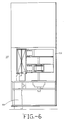
- Fig. 6 depicts moving mechanism below wafers in separately exhausted compartments of the present invention.
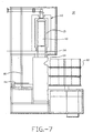
- Fig. 7 depicts a side view of isolated and independently purged stations.
- Fig. 8 depicts a diagram of a purge system according to the present invention.
- Fig. 9 depicts an EVTR elevation scheme according to the present invention.
- the plan view of the present invention shows three areas or stations. There is a front area called the wafer handling area 12. There is the center area beneath the process tube called the process area 14. There is an area behind that which is called the cool-down area, or cool-down chamber 16. In the wafer handling area 12, there are three major components. There is the cassette carousel 20 which stages twelve cassettes of wafers all the way up to 20 centimeters (eight inches). There is also a polar coordinate robot 22 and a shuttle 42.
- isolation doors 30 In the process area or chamber 14, there are isolation doors 30 separating it from the wafer handling area 12 and it has isolation doors 32 separating it from the cool-down area 16. In that process area 14, at the top the process tube and the boat door 38 of the process tube travels up and down within that area.
- wafers are brought in and moved up into the process tube so there is no activity other than that wafers are moving in and out of that region.
- the cool-down area 16 there is a separate shuttle in there which is able to move into the process area to take out completed loads of wafers and take them back into the rear of the system for cooling.
- Each of the chambers 12, 14, 16 has horizontal laminar flow across it.
- the entire wall of the system 10 includes a HEPA filter, which is known filter in the art.
- blowers which drive air on the order of 30 linear meters per minute (100 linear feet per minute) across those chambers to a return plenum and the return plenum allows air to recirculate so that air can run around continuously and which helps get it cleaner and cleaner as it recirculates through.
- the wafer handling area 12 has a completely separate air handling system so that it has its own filter, its own plenums and its own blower.
- the process chamber 14 or (process area) and the cool-down chamber 16 share the same blower. They have separate filters on their walls, but that area is co-mingled through the blower that services those two chambers. Both of those areas have separate nitrogen systems which allow, instead of running air, recirculating air or running air through and just dumping it.
- a nitrogen flow (or other suitable flow, such as argon) can purge those areas at a high flow rate of nitrogen. While doing a high flow purge, the exhaust is opened through a diverter which allows the nitrogen that is coming in and forcing out air to exhaust that out through the system exhaust.
- the flow rate is dropped down from a high flow to a low flow and then the low flow finishes clearing out the oxygen at which time the diverter is closed and the system 10 recirculates the nitrogen but it continues with the low flow to make up for leaks that may be in that portion of the system.
- Figs. 2A-2H show in schematic fashion the flow of material through a system 10 that is so-called a cold startup. It is a system that has never been run before and therefore it has no quartzware in it.
- the first thing to do is put in a boat 40.
- the shuttle 42 that is in the wafer handle area can come over the top of the polar coordinate robot 22 and move all the way to the front of the system 10 where there is a door which is the boat loading door. That door is opened and a clean boat 40 can be put into the system from the clean room side. This is a feature considered important because it does allow quartzware to get into the system very easily.
- a clean boat 40 is then placed into the system 10 and that clean boat 40 is moved to the rear of the system because it is desired to get two boats into the system.
- the clean boat 40 is placed onto the front shuttle 42. It then gets shuttled to the rear of the wafer handling area 12 (the first set of isolation doors).
- the front set of isolation doors 30, the front shuttle 42 would cantilever into the process area 14, then the rear isolation doors 32 open and the rear shuttle 44 moves forward into the process area and the two shuttles have interdigitated fingers 21, 23 that is shown in Fig. 1.
- This allows the two shuttles 42, 44 to come together inside the process area and the forward shuttle 42 which has both vertical and horizontal movement can drop down slightly, transferring the boat 40 to the rear shuttle 42 and then the rear shuttle 44 is backed out taking it into the cool-down area 16.
- the front shuttle 40 then moves forward, and the isolation doors 30, 32 are closed.
- a second boat 50 can be placed on the front shuttle 42 which is again moved all the way to the front of the system 10. The second boat 50 is then moved towards the rear of the wafer handling area 12 to the load position. Now, the polar coordinate robot 22 can begin taking wafers which have been placed in the cassette carrousel 20 previously, taking those wafers out and putting them into the slots of the boat 50. When the robot 22 then completes loading that boat 50, the front isolation doors 30 open and the shuttle 40 now transfers the boat 50 into the process chamber 14.
- the load door of the process chamber 14 has been brought down to its low position and the shuttle 42 reaches in over the top of the load door which has resting on it a quartz plug and then the boat 50 is set down onto the top of that quartz plug and is drawn back to the wafer handling area 12.
- the load door 38 can push the load up into the furnace.
- the boat 50 which had been previously placed in the cool-down chamber 16 is now transferred again to the front by the two shuttles 42, 44 coming together and the front shuttle 42, lifting it up slightly and withdrawing it into the wafer handling area 12.
- the isolation doors 30, 32 are closed again and the second boat 50 is now loaded full of wafers from the cassette carrousel 20 (a boat typically has 130 slots).
- the second boat 50 presumably has completed processing sometime either during or after the boat 40 that was transferred forward and just completed loading.
- the boat 50 in process then is lowered down into the bottom portion of the process area 14.
- the rear shuttle comes into the process area 14 and slips between the plug and the process boat (the process boat stands on legs on top of the plug) allowing the shuttle 42 to slip in between and then that shuttle 42 gets underneath and the load door 38 lowers slightly more transferring the weight to the rear shuttle 44 and then the rear shuttle 44 withdraws into the cool-down area 16.
- the rear isolation doors 32 are closed again.
- the front isolation doors 30 are opened and the boat that was just loaded now moves over the top of the load door, transferred to the load door, the shuttle withdrawn, and the load door then goes up moving the second batch into the process chamber 14.
- the boat 50 which has been cooling in the cool-down chamber has reached a temperature where the wafers can be handled, it then is transferred again by the two shuttles 42, 44 coming together and passed from the rear shuttle 44 to the front shuttle 42 and taken into the wafer handling area 12 where the boat 50 is now unloaded into the cassettes that it previously was unloaded from and now this boat 50 is reloaded with fresh wafers to be processed. Then the cycle continues to repeat, which allows for continuous processing.
- a rear view of the system 10 is shown. in that view, the element 60 of the system 10 can be seen which consists of the heater and the process tube shown swung out at the top of the system 10.
- the function is such that the entire element is setting on in its normal processing condition; a pneumatic system lifts up the process element into about 2.5 centimeters (one inch). It is then rolled towards the rear of the system on suitable rails, such as Thompson brand rails and when it reaches the end of its rolling travel it then swings out such that it is outside the frame of the system, cantilevered out over the system (the quartz tube is inside the element).
- the pneumatic system When it is swung outside the system 10, the pneumatic system then lowers that entire element down to a cart or table where the quartz tube is released form the flange that holds it inside the element 60 and its bolts are loosened and the flange removed which allows the quartz tube to come out of the element 60.
- the quartz tube can be resting on the cart or table and the element 60 is lifted up by the pneumatic system leaving behind the process tube so it can then be rolled out and a new process tube rolled underneath the element, lowered down again, the screws fastened and lifted up into the system and then rolled into the system so the entire exchange can be done on the order of ten minutes.
- the vacuum connection which goes up to the ball joint on the top of the tube remains in place, so a large section of vacuum tube comes out with the element and when the element is lowered down then that back connection is broken. This means that it is not necessary to climb up over the top of the system to release the back connection from the ball joint. It can be done after it is lowered down to the level for servicing. If it is an atmospheric system, there is no vacuum connection there but the eject lines do have to be disconnected (they are on flexible tubing). Similarly, this system is brought out, lowered down, and then the connection at the top can be broken for the eject line.
- the laminar flow 70 within the system 10 is to provide clean room type flows which carry away any particles.
- all the mechanisms within the system are isolated in some way.
- the elevator mechanism which lifts the load door and the process boat into the process chamber is in the exhaust mechanism (in the exhaust plenum).
- the motor is also below the system such that laminar flow air travels from the clean filter across the wafers into the return duct.
- the mechanisms are within that return duct so that any particles that might be generated there by the mechanical motion are swept away from the wafers and carried back to the filters where they can be swept out.
- Fig. 6 the moving mechanism for the robot into the carrousel
- those are both beneath the floor of the wafer handling area 12 of Fig. 1.
- the upper portion where the wafers are has a laminar flow travelling process from the robot side towards the carrousel side (where the return plenum is).
- the drive mechanism for the robot 22 and the drive mechanism for the carrousel 20 are below the plate which supports the carrousel and that area where those mechanisms are is in a separately exhaust area so that any particulates that are generated by those two mechanisms are drawn away from the wafer handling area and exhausted separately.
- Fig. 6 shows the silhouettes of the robot and the motor drive for the carrousel which are below the load plane.
- Fig. 7 shows in profile a side view in which the three areas of the system can be seen.
- the wafer handling area 12 (which is at the right-most side of Fig. 7) is shown without the laminar flow section which resides over the top of the carrousel.
- the process tube 13 is shown in silhouette with a boat 40 and a plug in it and the element insulation and heater coils surrounding it. This is shown as an LP system so the vacuum is coming out through the top of the system 10.
- On the left-most side is the cool-down chamber 16 showing its shuttle in profile.
- the process area 14 in the center is much deeper than the other two areas 12, 16 to allow the load door to come down below to a lower level such that the process boat can be set on top of the plug.
- a cage boat In a cage boat, a cylindrical quartz tube surrounds what might be the conventional boat. That cylindrical boat is split in half and must be opened up for wafers to be loaded.
- the present system has a cage boat removal or opening mechanism that when the boat is moved with its cage surrounding it into the wafer handling area, an arm mechanism pivots and comes underneath the front half of the cage and lifts up and connects with the cage and then pivots to open that boat such that wafers can now be loaded or unloaded from the cage boat.
- a laminar flow hood can be added over the front of the system. Then what is normally the front is moved back approximately 46 centimeters (18 inches) and a shelved laminar hood is added in front of the system to allow a place for the staging of cassette carriers so that the cassette carrier can be set in this laminar flow at the front of the system on a shelf at the front and opened for insertion into the carrousel.
- the carrousel 20 presents three cassettes at a time to the front of the system, so when the door is open the operator is then prompted to load or unload one of the three cassettes that are presented.
- FIG. 4 a right handed system is seen.
- a right handed system is defined by the side into which cassettes are loaded.
- Mirror image systems can also be provided and access is required only from one side of the system and the rear. Therefore, with mirror image systems two systems can be butted side by side reducing the amount of room needed for installation and operation.
- At the front of the system there is a touch screen which uses an electroluminescent display from which all functions of the system are controlled, including the process recipe and the system recipe which the sequencing of loads, unloads and purging cycle are determined. The purge cycles are completely programmable from that front panel to allow any of the separately purged chambers to be purged at the time and to the level specified at that front touch control panel.
- Fig. 8 (labeled EVTR purge systems scheme) it schematically illustrates the geometry depth used for the laminar flow and for the purge system. The elements are described and numbered there and the chambers are two separate circuits and are very similar in function with the exception that the circuit which includes the process chamber has included in it item number which is a heat exchanger.
- the EVTR purge system can be designed with two purge systems. One is for wafer handling module purge system, the other is for the furnace module purge system.
- the two purge systems are similar in concept but different in geometries.
- Both purge systems include the following components as depicted in Fig. 8. These components include a blower, VLSI grade filter, flow diverter, diverter actuator, main flow valve, bypass flow valve, entrance plenum, exit plenum, ducting, flow sensor, and heat exchanger.
- the materials used in the design of a purge system must be Class 1 clean room compatible.
- the purge system to be sealed must withstand two in water pressure differential.
- the purge system heat load is regulated by boat withdrawal rate. The design allows recirculation of the purge gas.
- That heat exchanger (which is a water cooled heat exchanger) removes the heat which otherwise in more conventional systems is carried away by the fact that air is drawn across there and exhausted. Since this system has the capability of recirculating nitrogen or air, the air or the nitrogen that is being recirculated must be cooled. The heat exchanger provides that capability. Item illustrates the diverter valve which allows the flow to be either recirculated or exhausted from the system.
- Fig. 9 (labeled EVTR elevation) shows just that - the elevations of the system 10. Looking at the left-most side (Fig. 9A), there it is the non-access side and there are a number of panels which are merely bolted in place where access is normally not expected. The system is designed not to require any access from that side. In looking at the profile of the system, it can be seen that there is at the clean room wall the system is lower than further back in the maintenance or chase area. The penetration through the wall is 26 meters (104 inches) high and the system has ten centimeter (four inch) clearance underneath it to allow for those clean rooms which require flow underneath the systems.
- the height is 2.9 meters (115 inches) including the four inch access underneath the system. There is nothing of the system which comes above that 2.9 meters (115 inches).
- the gas lines must come in from the top into the gas tray and the furnace air exhaust and inlets also come in through the top for the connections made from the house facilities above the system.
- FIG. 9B shows the front clean room side view and shows the width of the system (which is approximately 1.2 meters (46 inches) wide and has its frame and with its cosmetic panels in place is approximately 1.2 meters (48 inches)).
- the two doors which are in front of the system.
- a right-hand system is illustrated and there is a cassette load door which swings out and in that view can be seen where the cassettes would normally go in.
- FIG. 9C There is a left-handed door there where clean boats are normally brought into the system.
- FIG. 9D In the access side illustration (Fig. 9C), there the area where the gas panel is in the system is illustrated.
- the right-most illustration (Fig. 9D) shows the rear with the boat removal access door 48 on the right-hand side.
- Fig. 9D shows the rear with the boat removal access door 48 on the right-hand side.
- the power distribution box on the left-hand side
- a square which illustrates where a control panel can be mounted such that the controlling system can be from either the rear or from the front. It can only be from one end at a time so a switch selects either the front control panel or the rear control panel.
Landscapes
- Engineering & Computer Science (AREA)
- Mechanical Engineering (AREA)
- General Engineering & Computer Science (AREA)
- Container, Conveyance, Adherence, Positioning, Of Wafer (AREA)
Claims (9)
- Vertikales Wärmereaktorsystem, das durch folgendes gekennzeichnet ist:eine Scheibenbearbeitungskammer (12), in der Halbleiterscheiben zur Verarbeitung in einem Reaktorsystem positioniert werden, und aus der verarbeitete Scheiben aus dem Reaktorsystem entfernt werden, wobei die genannte Scheibenbearbeitungskammer einen Karusselwagen (20) aufweist, der dazu dient, die Mehrzahl der Scheiben vor und nach der Verarbeitung zu halten;eine Prozeßkammer (14) zur Verarbeitung der aus der genannten Scheibenbearbeitungskammer empfangenen Scheiben;eine erste Öffnung zwischen der genannten Prozeßkammer und der genannten Scheibenbearbeitungskammer, wobei eine erste Tür (30) zum dichten Verschluß der genannten ersten Öffnung vorgesehen ist;eine Abkühlkammer (16), in der die verarbeiteten Scheiben aus der genannten Prozeßkammer abkühlen;eine zweite Öffnung zwischen der genannten Abkühlkammer und der genannten Prozeßkammer, wobei eine zweite Tür (32) zum dichten Verschluß der genannten zweiten Öffnung vorgesehen ist.
- Reaktorsystem nach Anspruch 1, ferner gekennzeichnet durch einen Roboter (22) zur Übertragung der genannten Mehrzahl von Scheiben aus dem genannten Karusselwagen und zur Plazierung der Scheiben auf einem sich in der genannten Bearbeitungskammer befindenden Schiffchen (50).
- Reaktorsystem nach Anspruch 1, ferner gekennzeichnet durch eine erste Pendeleinrichtung (42), die dazu dient, das mit den Scheiben gefüllte Schiffchen (50) von der genannten Bearbeitungskammer zu der genannten Prozeßkammer zu befördern, und mit einer zweiten Pendeleinrichtung (44), die dazu dient, das genannte mit den verarbeiteten Scheiben gefüllte Schiffchen von der genannten Prozeßkammer zu der genannten Abkühlkammer zu transportieren.
- Reaktorsystem nach einem der vorstehenden Ansprüche, dadurch gekennzeichnet, daß die genannte Prozeßkammer einen ersten Bereich aufweist, der sich in Verbindung mit der genannten ersten Öffnung befindet, und mit einem zweiten Bereich, der oberhalb des genannten ersten Bereichs angeordnet ist, wobei die genannte Prozeßkammer einen Ofen aufweist, der sich in dem zweiten Bereich befindet.
- Reaktorsystem nach Anspruch 4, dadurch gekennzeichnet, daß die genannte Prozeßkammer ferner eine Prozeßröhre (64) und eine Ladetüreinrichtung (38) zur Aufnahme der genannten ersten Pendeleinrichtung aufweist, die das genannte Schiffchen mit den Scheiben in der genannten Bearbeitungskammer trägt, und wobei das Schiffchen nach oben in den Ofen befördert wird.
- Reaktorsystem nach einem der vorstehenden Ansprüche, wobei das System eine Einrichtung zum Entleeren der Kammern aufweist, wobei die genannte Bearbeitungskammer unabhängig von der Prozeß- und der Abkühlkammer entleert werden kann, wobei die genannte Einrichtung ein erstes Entleerungssystem für die genannte Bearbeitungskammer und ein zweites Entleerungssystem für die genannte Prozeßkammer aufweist.
- Reaktorsystem nach Anspruch 1, wobei die genannte Scheibenbearbeitungskammer eine erste Öffnung umfaßt, die aus dem Reaktorsystem hinaus führt; und mit einer dritten Tür (36) zum dichten Verschluß dieser Öffnung.
- Reaktorsystem nach Anspruch 7, wobei die genannte Abkühlkammer eine zweite Öffnung aufweist, die aus dem Reaktorsystem hinaus führt; und mit einer vierten Tür (48) zum dichten Verschluß dieser Öffnung.
- Reaktorsystem nach einem der vorstehenden Ansprüche, wobei die genannte Prozeßkammer einen Ofen aufweist, in dem Scheiben verarbeitet werden, wobei der genannte Ofen eine Prozeßröhre (60) mit einer Längsachse aufweist, die sich vertikal in der genannten Prozeßkammer erstreckt.
Applications Claiming Priority (3)
| Application Number | Priority Date | Filing Date | Title |
|---|---|---|---|
| US390595 | 1989-08-07 | ||
| US07/390,595 US5254170A (en) | 1989-08-07 | 1989-08-07 | Enhanced vertical thermal reactor system |
| PCT/US1990/004302 WO1991002106A1 (en) | 1989-08-07 | 1990-08-01 | Enhanced vertical thermal reactor system |
Publications (3)
| Publication Number | Publication Date |
|---|---|
| EP0485461A1 EP0485461A1 (de) | 1992-05-20 |
| EP0485461A4 EP0485461A4 (en) | 1993-09-15 |
| EP0485461B1 true EP0485461B1 (de) | 1997-05-07 |
Family
ID=23543113
Family Applications (1)
| Application Number | Title | Priority Date | Filing Date |
|---|---|---|---|
| EP90911896A Expired - Lifetime EP0485461B1 (de) | 1989-08-07 | 1990-08-01 | Senkrechtes wärmereaktorsystem |
Country Status (4)
| Country | Link |
|---|---|
| US (2) | US5254170A (de) |
| EP (1) | EP0485461B1 (de) |
| DE (1) | DE69030667T2 (de) |
| WO (1) | WO1991002106A1 (de) |
Families Citing this family (44)
| Publication number | Priority date | Publication date | Assignee | Title |
|---|---|---|---|---|
| JP2751975B2 (ja) * | 1991-12-20 | 1998-05-18 | 株式会社日立製作所 | 半導体処理装置のロードロック室 |
| ATE157159T1 (de) * | 1992-06-03 | 1997-09-15 | Esec Sa | Vorrichtung zur wärmebehandlung eines magazins für systemträger mit elektronischen bauelementen |
| JP3186262B2 (ja) * | 1992-10-14 | 2001-07-11 | ソニー株式会社 | 半導体装置の製造方法 |
| US5527390A (en) * | 1993-03-19 | 1996-06-18 | Tokyo Electron Kabushiki | Treatment system including a plurality of treatment apparatus |
| JP3543987B2 (ja) * | 1993-12-03 | 2004-07-21 | 東京エレクトロン株式会社 | 処理装置 |
| KR100221983B1 (ko) * | 1993-04-13 | 1999-09-15 | 히가시 데쓰로 | 처리장치 |
| TW273574B (de) * | 1993-12-10 | 1996-04-01 | Tokyo Electron Co Ltd | |
| USD365584S (en) | 1993-12-15 | 1995-12-26 | Tokyo Electron Kabushiki Kaisha | Semiconductor manufacturing device |
| JPH0936198A (ja) * | 1995-07-19 | 1997-02-07 | Hitachi Ltd | 真空処理装置およびそれを用いた半導体製造ライン |
| US5788304A (en) | 1996-05-17 | 1998-08-04 | Micron Technology, Inc. | Wafer carrier having both a rigid structure and resistance to corrosive environments |
| US5975740A (en) | 1996-05-28 | 1999-11-02 | Applied Materials, Inc. | Apparatus, method and medium for enhancing the throughput of a wafer processing facility using a multi-slot cool down chamber and a priority transfer scheme |
| KR100252210B1 (ko) * | 1996-12-24 | 2000-04-15 | 윤종용 | 반도체장치 제조용 건식식각장치 |
| US6432203B1 (en) * | 1997-03-17 | 2002-08-13 | Applied Komatsu Technology, Inc. | Heated and cooled vacuum chamber shield |
| US6034000A (en) * | 1997-07-28 | 2000-03-07 | Applied Materials, Inc. | Multiple loadlock system |
| DE69734877T2 (de) * | 1997-09-10 | 2006-09-14 | Samsung Electronics Co., Ltd., Suwon | Vorrichtung zur Herstellung von einem Halbleiter-Bauelement und ein diese Vorrichtung verwendendes Verfahren zur Herstellung einer Polysilicium-Schicht |
| US6688375B1 (en) * | 1997-10-14 | 2004-02-10 | Applied Materials, Inc. | Vacuum processing system having improved substrate heating and cooling |
| NL1008143C2 (nl) | 1998-01-27 | 1999-07-28 | Asm Int | Stelsel voor het behandelen van wafers. |
| JP2001085346A (ja) * | 1999-09-17 | 2001-03-30 | Nec Kyushu Ltd | 半導体装置の製造装置及び半導体装置の製造方法 |
| US6410455B1 (en) * | 1999-11-30 | 2002-06-25 | Wafermasters, Inc. | Wafer processing system |
| US6402508B2 (en) * | 1999-12-09 | 2002-06-11 | Tokyo Electron Limited | Heat and cooling treatment apparatus and substrate processing system |
| US6949143B1 (en) | 1999-12-15 | 2005-09-27 | Applied Materials, Inc. | Dual substrate loadlock process equipment |
| KR20030032034A (ko) | 2000-09-15 | 2003-04-23 | 어플라이드 머티어리얼스, 인코포레이티드 | 처리 장비용 두 개의 이중 슬롯 로드록 |
| US6951804B2 (en) * | 2001-02-02 | 2005-10-04 | Applied Materials, Inc. | Formation of a tantalum-nitride layer |
| US7316966B2 (en) * | 2001-09-21 | 2008-01-08 | Applied Materials, Inc. | Method for transferring substrates in a load lock chamber |
| US6573198B2 (en) | 2001-10-10 | 2003-06-03 | Asm International N.V. | Earthquake protection for semiconductor processing equipment |
| US20070243317A1 (en) * | 2002-07-15 | 2007-10-18 | Du Bois Dale R | Thermal Processing System and Configurable Vertical Chamber |
| US20060083495A1 (en) * | 2002-07-15 | 2006-04-20 | Qiu Taiquing | Variable heater element for low to high temperature ranges |
| KR100486690B1 (ko) * | 2002-11-29 | 2005-05-03 | 삼성전자주식회사 | 기판 이송 모듈의 오염을 제어할 수 있는 기판 처리 장치및 방법 |
| US7207766B2 (en) | 2003-10-20 | 2007-04-24 | Applied Materials, Inc. | Load lock chamber for large area substrate processing system |
| US7497414B2 (en) | 2004-06-14 | 2009-03-03 | Applied Materials, Inc. | Curved slit valve door with flexible coupling |
| US7503981B2 (en) * | 2004-12-02 | 2009-03-17 | The Trustees Of Dartmouth College | Removal of minerals from cellulosic biomass |
| US7553516B2 (en) * | 2005-12-16 | 2009-06-30 | Asm International N.V. | System and method of reducing particle contamination of semiconductor substrates |
| US7845891B2 (en) | 2006-01-13 | 2010-12-07 | Applied Materials, Inc. | Decoupled chamber body |
| US7665951B2 (en) | 2006-06-02 | 2010-02-23 | Applied Materials, Inc. | Multiple slot load lock chamber and method of operation |
| US7845618B2 (en) | 2006-06-28 | 2010-12-07 | Applied Materials, Inc. | Valve door with ball coupling |
| US8124907B2 (en) | 2006-08-04 | 2012-02-28 | Applied Materials, Inc. | Load lock chamber with decoupled slit valve door seal compartment |
| KR20110112074A (ko) * | 2010-04-06 | 2011-10-12 | 삼성전자주식회사 | 기판 처리 장치 및 방법 |
| US20130084147A1 (en) * | 2011-10-03 | 2013-04-04 | Denton Vacuum, L.L.C. | Semiconductor wafer treatment system |
| US9650727B2 (en) * | 2013-07-03 | 2017-05-16 | Applied Materials, Inc. | Reactor gas panel common exhaust |
| JP6374775B2 (ja) * | 2014-11-25 | 2018-08-15 | 東京エレクトロン株式会社 | 基板搬送システム及びこれを用いた熱処理装置 |
| KR101736855B1 (ko) * | 2015-05-29 | 2017-05-18 | 세메스 주식회사 | 기판 처리 설비 |
| US9849937B1 (en) * | 2016-08-25 | 2017-12-26 | Timothy B. Overbey | Boating safety device |
| DE102017000429A1 (de) | 2017-01-18 | 2018-07-19 | Centrotherm Photovoltaics Ag | Prozessofen mit Ofenmodulen |
| US10858738B2 (en) * | 2018-03-29 | 2020-12-08 | Asm International N.V. | Wafer boat cooldown device |
Family Cites Families (25)
| Publication number | Priority date | Publication date | Assignee | Title |
|---|---|---|---|---|
| US3805736A (en) * | 1971-12-27 | 1974-04-23 | Ibm | Apparatus for diffusion limited mass transport |
| SU954512A1 (ru) * | 1980-09-12 | 1982-08-30 | Дзержинский филиал Научно-исследовательского и конструкторского института химического машиностроения | Устройство дл нанесени покрытий из паровой (газовой) фазы |
| US4500407A (en) * | 1983-07-19 | 1985-02-19 | Varian Associates, Inc. | Disk or wafer handling and coating system |
| US4593644A (en) * | 1983-10-26 | 1986-06-10 | Rca Corporation | Continuous in-line deposition system |
| GB8332394D0 (en) * | 1983-12-05 | 1984-01-11 | Pilkington Brothers Plc | Coating apparatus |
| US4534314A (en) * | 1984-05-10 | 1985-08-13 | Varian Associates, Inc. | Load lock pumping mechanism |
| US4640223A (en) * | 1984-07-24 | 1987-02-03 | Dozier Alfred R | Chemical vapor deposition reactor |
| JPS6162739A (ja) * | 1984-09-03 | 1986-03-31 | Sanki Eng Co Ltd | クリ−ントンネル |
| JPS61105853A (ja) * | 1984-10-30 | 1986-05-23 | Anelva Corp | オ−トロ−ダ− |
| US4576830A (en) * | 1984-11-05 | 1986-03-18 | Chronar Corp. | Deposition of materials |
| JPS62221107A (ja) * | 1986-03-24 | 1987-09-29 | Hitachi Ltd | 処理装置 |
| JPS62166624U (de) * | 1986-04-14 | 1987-10-22 | ||
| US4767251A (en) * | 1986-05-06 | 1988-08-30 | Amtech Systems, Inc. | Cantilever apparatus and method for loading wafer boats into cantilever diffusion tubes |
| US4770590A (en) * | 1986-05-16 | 1988-09-13 | Silicon Valley Group, Inc. | Method and apparatus for transferring wafers between cassettes and a boat |
| US4717461A (en) * | 1986-09-15 | 1988-01-05 | Machine Technology, Inc. | System and method for processing workpieces |
| JPS6384016A (ja) * | 1986-09-26 | 1988-04-14 | Sumitomo Metal Ind Ltd | 気相成長装置 |
| JPS63128710A (ja) * | 1986-11-19 | 1988-06-01 | Mitsubishi Electric Corp | 反応炉 |
| FR2620049B2 (fr) * | 1986-11-28 | 1989-11-24 | Commissariat Energie Atomique | Procede de traitement, stockage et/ou transfert d'un objet dans une atmosphere de haute proprete, et conteneur pour la mise en oeuvre de ce procede |
| US4926793A (en) * | 1986-12-15 | 1990-05-22 | Shin-Etsu Handotai Co., Ltd. | Method of forming thin film and apparatus therefor |
| JPS63157870A (ja) * | 1986-12-19 | 1988-06-30 | Anelva Corp | 基板処理装置 |
| JPS63161612A (ja) * | 1986-12-25 | 1988-07-05 | Toshiba Ceramics Co Ltd | 縦型炉 |
| JP2503495B2 (ja) * | 1987-03-30 | 1996-06-05 | 株式会社ニコン | 露光装置及び露光方法 |
| JPH01125821A (ja) * | 1987-11-10 | 1989-05-18 | Matsushita Electric Ind Co Ltd | 気相成長装置 |
| JP2502661B2 (ja) * | 1988-03-04 | 1996-05-29 | 松下電器産業株式会社 | 気相成長装置 |
| NL8900544A (nl) * | 1989-03-06 | 1990-10-01 | Asm Europ | Behandelingsstelsel, behandelingsvat en werkwijze voor het behandelen van een substraat. |
-
1989
- 1989-08-07 US US07/390,595 patent/US5254170A/en not_active Expired - Lifetime
-
1990
- 1990-08-01 DE DE69030667T patent/DE69030667T2/de not_active Expired - Fee Related
- 1990-08-01 WO PCT/US1990/004302 patent/WO1991002106A1/en not_active Ceased
- 1990-08-01 EP EP90911896A patent/EP0485461B1/de not_active Expired - Lifetime
-
1991
- 1991-01-18 US US07/644,235 patent/US5336325A/en not_active Expired - Lifetime
Also Published As
| Publication number | Publication date |
|---|---|
| DE69030667T2 (de) | 1997-10-23 |
| US5336325A (en) | 1994-08-09 |
| EP0485461A4 (en) | 1993-09-15 |
| EP0485461A1 (de) | 1992-05-20 |
| DE69030667D1 (de) | 1997-06-12 |
| US5254170A (en) | 1993-10-19 |
| WO1991002106A1 (en) | 1991-02-21 |
Similar Documents
| Publication | Publication Date | Title |
|---|---|---|
| US5254170A (en) | Enhanced vertical thermal reactor system | |
| US10930536B2 (en) | Workpiece stocker with circular configuration | |
| KR100406337B1 (ko) | 기판이송및처리시스템 | |
| US6273110B1 (en) | Automated semiconductor processing system | |
| US7637707B2 (en) | Apparatus for storing and moving a cassette | |
| KR100235917B1 (ko) | 진공처리장치 | |
| EP1134641B1 (de) | Vorrichtung zum Speichern und Bewegen einer Kassette | |
| KR100233310B1 (ko) | 열처리장치 | |
| US6723174B2 (en) | Automated semiconductor processing system | |
| US6942738B1 (en) | Automated semiconductor processing system | |
| US9403196B2 (en) | Treatment device for transport and storage boxes | |
| WO2000002675A9 (en) | Automated semiconductor processing system | |
| JPH10256346A (ja) | カセット搬出入機構及び半導体製造装置 | |
| JP3082389B2 (ja) | クリーンルーム用保管庫 | |
| US5364225A (en) | Method of printed circuit panel manufacture | |
| US6852601B2 (en) | Heat treatment method that includes a low negative pressure | |
| US5226812A (en) | Vertical type heat-treating apparatus | |
| US6736148B2 (en) | Automated semiconductor processing system | |
| KR100650807B1 (ko) | 기판반송장치, 처리장치, 기판의 처리시스템, 반송방법, 수납장치 및 수용박스 | |
| JP2001093957A (ja) | 電子部品の製造装置および電子部品の製造方法 | |
| JP3176153B2 (ja) | 半導体製造装置 | |
| JP2876250B2 (ja) | 縦型熱処理装置 | |
| JP2645357B2 (ja) | 処理装置 | |
| JP2006108348A (ja) | 基板処理装置 | |
| JP2000091399A (ja) | 半導体製造装置 |
Legal Events
| Date | Code | Title | Description |
|---|---|---|---|
| PUAI | Public reference made under article 153(3) epc to a published international application that has entered the european phase |
Free format text: ORIGINAL CODE: 0009012 |
|
| 17P | Request for examination filed |
Effective date: 19920302 |
|
| AK | Designated contracting states |
Kind code of ref document: A1 Designated state(s): AT BE CH DE DK ES FR GB IT LI LU NL SE |
|
| RBV | Designated contracting states (corrected) |
Designated state(s): DE FR IT |
|
| A4 | Supplementary search report drawn up and despatched |
Effective date: 19930723 |
|
| AK | Designated contracting states |
Kind code of ref document: A4 Designated state(s): AT BE CH DE DK ES FR GB IT LI LU NL SE |
|
| RAP1 | Party data changed (applicant data changed or rights of an application transferred) |
Owner name: ASM VT, INC. |
|
| 17Q | First examination report despatched |
Effective date: 19940711 |
|
| GRAG | Despatch of communication of intention to grant |
Free format text: ORIGINAL CODE: EPIDOS AGRA |
|
| GRAH | Despatch of communication of intention to grant a patent |
Free format text: ORIGINAL CODE: EPIDOS IGRA |
|
| GRAH | Despatch of communication of intention to grant a patent |
Free format text: ORIGINAL CODE: EPIDOS IGRA |
|
| GRAA | (expected) grant |
Free format text: ORIGINAL CODE: 0009210 |
|
| AK | Designated contracting states |
Kind code of ref document: B1 Designated state(s): DE FR IT |
|
| REF | Corresponds to: |
Ref document number: 69030667 Country of ref document: DE Date of ref document: 19970612 |
|
| ET | Fr: translation filed | ||
| PLBE | No opposition filed within time limit |
Free format text: ORIGINAL CODE: 0009261 |
|
| STAA | Information on the status of an ep patent application or granted ep patent |
Free format text: STATUS: NO OPPOSITION FILED WITHIN TIME LIMIT |
|
| 26N | No opposition filed | ||
| REG | Reference to a national code |
Ref country code: FR Ref legal event code: TP |
|
| PGFP | Annual fee paid to national office [announced via postgrant information from national office to epo] |
Ref country code: FR Payment date: 20040810 Year of fee payment: 15 |
|
| PGFP | Annual fee paid to national office [announced via postgrant information from national office to epo] |
Ref country code: DE Payment date: 20040812 Year of fee payment: 15 |
|
| PG25 | Lapsed in a contracting state [announced via postgrant information from national office to epo] |
Ref country code: IT Free format text: LAPSE BECAUSE OF NON-PAYMENT OF DUE FEES;WARNING: LAPSES OF ITALIAN PATENTS WITH EFFECTIVE DATE BEFORE 2007 MAY HAVE OCCURRED AT ANY TIME BEFORE 2007. THE CORRECT EFFECTIVE DATE MAY BE DIFFERENT FROM THE ONE RECORDED. Effective date: 20050801 |
|
| PG25 | Lapsed in a contracting state [announced via postgrant information from national office to epo] |
Ref country code: DE Free format text: LAPSE BECAUSE OF NON-PAYMENT OF DUE FEES Effective date: 20060301 |
|
| PG25 | Lapsed in a contracting state [announced via postgrant information from national office to epo] |
Ref country code: FR Free format text: LAPSE BECAUSE OF NON-PAYMENT OF DUE FEES Effective date: 20060428 |
|
| REG | Reference to a national code |
Ref country code: FR Ref legal event code: ST Effective date: 20060428 |