EP0484882A1 - Kontinuierliches Warmband-Walzsystem - Google Patents
Kontinuierliches Warmband-Walzsystem Download PDFInfo
- Publication number
- EP0484882A1 EP0484882A1 EP91118839A EP91118839A EP0484882A1 EP 0484882 A1 EP0484882 A1 EP 0484882A1 EP 91118839 A EP91118839 A EP 91118839A EP 91118839 A EP91118839 A EP 91118839A EP 0484882 A1 EP0484882 A1 EP 0484882A1
- Authority
- EP
- European Patent Office
- Prior art keywords
- rolling
- train
- roughing train
- rolled
- hot strip
- Prior art date
- Legal status (The legal status is an assumption and is not a legal conclusion. Google has not performed a legal analysis and makes no representation as to the accuracy of the status listed.)
- Granted
Links
- 238000005096 rolling process Methods 0.000 title claims abstract description 176
- 238000000034 method Methods 0.000 title claims description 30
- 239000000463 material Substances 0.000 claims abstract description 73
- 238000005304 joining Methods 0.000 claims abstract description 49
- 238000011144 upstream manufacturing Methods 0.000 claims description 9
- XLYOFNOQVPJJNP-UHFFFAOYSA-N water Substances O XLYOFNOQVPJJNP-UHFFFAOYSA-N 0.000 claims description 8
- 230000009467 reduction Effects 0.000 abstract description 26
- 239000007789 gas Substances 0.000 description 10
- 238000009434 installation Methods 0.000 description 10
- 238000012986 modification Methods 0.000 description 7
- 230000004048 modification Effects 0.000 description 7
- 238000009749 continuous casting Methods 0.000 description 6
- 230000008569 process Effects 0.000 description 5
- 238000010438 heat treatment Methods 0.000 description 4
- 229910000831 Steel Inorganic materials 0.000 description 3
- 230000008901 benefit Effects 0.000 description 3
- 230000002542 deteriorative effect Effects 0.000 description 3
- 238000012423 maintenance Methods 0.000 description 3
- 239000010959 steel Substances 0.000 description 3
- IJGRMHOSHXDMSA-UHFFFAOYSA-N Atomic nitrogen Chemical compound N#N IJGRMHOSHXDMSA-UHFFFAOYSA-N 0.000 description 2
- 230000008859 change Effects 0.000 description 2
- 238000010276 construction Methods 0.000 description 2
- 238000001816 cooling Methods 0.000 description 2
- 238000005520 cutting process Methods 0.000 description 2
- 230000001050 lubricating effect Effects 0.000 description 2
- 238000004519 manufacturing process Methods 0.000 description 2
- 230000003647 oxidation Effects 0.000 description 2
- 238000007254 oxidation reaction Methods 0.000 description 2
- 229910001220 stainless steel Inorganic materials 0.000 description 2
- 230000001360 synchronised effect Effects 0.000 description 2
- 238000000429 assembly Methods 0.000 description 1
- 230000000712 assembly Effects 0.000 description 1
- 238000006243 chemical reaction Methods 0.000 description 1
- 238000005097 cold rolling Methods 0.000 description 1
- 238000007796 conventional method Methods 0.000 description 1
- 238000002474 experimental method Methods 0.000 description 1
- 238000005098 hot rolling Methods 0.000 description 1
- 238000010348 incorporation Methods 0.000 description 1
- 239000007788 liquid Substances 0.000 description 1
- 239000000314 lubricant Substances 0.000 description 1
- 229910052757 nitrogen Inorganic materials 0.000 description 1
- 238000013021 overheating Methods 0.000 description 1
- 238000005554 pickling Methods 0.000 description 1
- 230000003014 reinforcing effect Effects 0.000 description 1
- 238000004904 shortening Methods 0.000 description 1
- 239000010935 stainless steel Substances 0.000 description 1
Images


Classifications
-
- B—PERFORMING OPERATIONS; TRANSPORTING
- B21—MECHANICAL METAL-WORKING WITHOUT ESSENTIALLY REMOVING MATERIAL; PUNCHING METAL
- B21B—ROLLING OF METAL
- B21B15/00—Arrangements for performing additional metal-working operations specially combined with or arranged in, or specially adapted for use in connection with, metal-rolling mills
- B21B15/0085—Joining ends of material to continuous strip, bar or sheet
-
- B—PERFORMING OPERATIONS; TRANSPORTING
- B21—MECHANICAL METAL-WORKING WITHOUT ESSENTIALLY REMOVING MATERIAL; PUNCHING METAL
- B21B—ROLLING OF METAL
- B21B1/00—Metal-rolling methods or mills for making semi-finished products of solid or profiled cross-section; Sequence of operations in milling trains; Layout of rolling-mill plant, e.g. grouping of stands; Succession of passes or of sectional pass alternations
- B21B1/22—Metal-rolling methods or mills for making semi-finished products of solid or profiled cross-section; Sequence of operations in milling trains; Layout of rolling-mill plant, e.g. grouping of stands; Succession of passes or of sectional pass alternations for rolling plates, strips, bands or sheets of indefinite length
- B21B1/24—Metal-rolling methods or mills for making semi-finished products of solid or profiled cross-section; Sequence of operations in milling trains; Layout of rolling-mill plant, e.g. grouping of stands; Succession of passes or of sectional pass alternations for rolling plates, strips, bands or sheets of indefinite length in a continuous or semi-continuous process
- B21B1/26—Metal-rolling methods or mills for making semi-finished products of solid or profiled cross-section; Sequence of operations in milling trains; Layout of rolling-mill plant, e.g. grouping of stands; Succession of passes or of sectional pass alternations for rolling plates, strips, bands or sheets of indefinite length in a continuous or semi-continuous process by hot-rolling, e.g. Steckel hot mill
-
- B—PERFORMING OPERATIONS; TRANSPORTING
- B21—MECHANICAL METAL-WORKING WITHOUT ESSENTIALLY REMOVING MATERIAL; PUNCHING METAL
- B21B—ROLLING OF METAL
- B21B45/00—Devices for surface or other treatment of work, specially combined with or arranged in, or specially adapted for use in connection with, metal-rolling mills
- B21B45/04—Devices for surface or other treatment of work, specially combined with or arranged in, or specially adapted for use in connection with, metal-rolling mills for de-scaling, e.g. by brushing
- B21B45/08—Devices for surface or other treatment of work, specially combined with or arranged in, or specially adapted for use in connection with, metal-rolling mills for de-scaling, e.g. by brushing hydraulically
-
- B—PERFORMING OPERATIONS; TRANSPORTING
- B21—MECHANICAL METAL-WORKING WITHOUT ESSENTIALLY REMOVING MATERIAL; PUNCHING METAL
- B21B—ROLLING OF METAL
- B21B13/00—Metal-rolling stands, i.e. an assembly composed of a stand frame, rolls, and accessories
- B21B13/02—Metal-rolling stands, i.e. an assembly composed of a stand frame, rolls, and accessories with axes of rolls arranged horizontally
- B21B2013/021—Twin mills
-
- B—PERFORMING OPERATIONS; TRANSPORTING
- B21—MECHANICAL METAL-WORKING WITHOUT ESSENTIALLY REMOVING MATERIAL; PUNCHING METAL
- B21B—ROLLING OF METAL
- B21B2265/00—Forming parameters
- B21B2265/10—Compression, e.g. longitudinal compression
-
- B—PERFORMING OPERATIONS; TRANSPORTING
- B21—MECHANICAL METAL-WORKING WITHOUT ESSENTIALLY REMOVING MATERIAL; PUNCHING METAL
- B21B—ROLLING OF METAL
- B21B9/00—Measures for carrying out rolling operations under special conditions, e.g. in vacuum or inert atmosphere to prevent oxidation of work; Special measures for removing fumes from rolling mills
-
- Y—GENERAL TAGGING OF NEW TECHNOLOGICAL DEVELOPMENTS; GENERAL TAGGING OF CROSS-SECTIONAL TECHNOLOGIES SPANNING OVER SEVERAL SECTIONS OF THE IPC; TECHNICAL SUBJECTS COVERED BY FORMER USPC CROSS-REFERENCE ART COLLECTIONS [XRACs] AND DIGESTS
- Y10—TECHNICAL SUBJECTS COVERED BY FORMER USPC
- Y10T—TECHNICAL SUBJECTS COVERED BY FORMER US CLASSIFICATION
- Y10T29/00—Metal working
- Y10T29/45—Scale remover or preventor
- Y10T29/4533—Fluid impingement
- Y10T29/4544—Liquid jet
Definitions
- the present invention relates to a continuous hot strip rolling system and a method thereof. More particularly, the present invention pertains to a continuous hot strip rolling system in which bars are joined to each other between a roughing train and a finishing train for continuous rolling, and a method thereof.
- joining continuous rolling has been desired because it can improve feeding of thin strips, because it enables a shape control function utilizing tension rolling to be provided, because it enables a high reduction rolling to be conducted in a subsequent stand due to supply of a lubricant, and because it enables strip curving camber to be reduced.
- Generation of camber causes troubles not only in the finish rolling process but also in the subsequent processes, such as a pickling process or cold rolling process. When strips have camber, the leading and trailing ends of that strip must be cut off, thus greatly reducing yield.
- These four-high mill stands are disposed separately at a distance from each other, which distance increases as the material being rolled becomes longer due to rolling so that the same material being rolled is not caught by two adjacent mill stands at the same time, as in the case of U. S. Patent No. 4,706,871.
- This arrangement of the four-high mill stands is advantageous, because it allows individual mill stand to be driven independently and thus allows inexpensive motors, such as a synchronous motor which does not require speed control, to be used.
- a single reversable roughing mill stand for conducting the unidirectional rolling is provided in place of the roughing train.
- JP, A, 61- 17305 and JP, A, 61-56708 have disclosed the use of a common housing for a two-high mill and a four-high mill to achieve high reduction rolling.
- JP, A, 50-109866 has proposed the incorporation of both a planetary mill and two sets of two-high mills in a common housing.
- a descaling device for ejecting water under pressure is provided on the rolling line for peeling off or removing the scale on the surface of the material to be rolled.
- the water ejecting nozzle of such a descaling device is generally of the fixed type
- JP, A, 63-68213 discloses a descaling device having a pivotal nozzle to improve the scale removal performance.
- JP, A, 50-95160 which discloses a rolling system in which a planetary mill and two sets of two-high mills are disposed close to each other, a gas device is provided to cover the portions of the material being rolled between the planetary mill and the two-high mill located adjacent to the planetray mill and between the two two-high mills, with an inactive or reducing gas in order to prevent generation of scale.
- the work rolls in the four-high mill stands are subjected to upper and lower opposite horizontal forces, and are thereby moved in a horizontal direction due to backlash between bearing boxes of the work rolls and a housing thereof, thus making the draft non-uniform in the lateral direction.
- the non-uniformity of the rolling reduction in the lateral direction is increased, thus increasing camber.
- the joining device since the bar is rolled to a thickness of 30 to 40 mm in the roughing rolling, when the joining time is long, the joining device must travel a long distance to join the bars without using a looper. Assuming that the conventional joining time is about one minute, if the rolling rate at the exit of the finishing train is 600 m/min to obtain a 2 mm thick product while the rolling rate at the entrance of the finishing train is 30 m/min for bars having a thickness of 40 mm, the joining machine must travel 30 m. When a looper is used, a 30 m long looper is required, which is quite unpractical.
- An object of the present invention is to provide a continuous hot strip rolling system capable of stable joining continuous rolling by reducing generation of camber in the rough rolling process, and a method thereof.
- Another object of the present invention is to provide a continuous hot strip rolling system capable of shortening the length of the overall system.
- Further object of the present invention is to provide a continuous hot strip rolling system capable of rational bar joining by reducing reduction in the temperature of the bar which occurs until the bar reaches a joining position, and a method thereof.
- a continuous hot strip rolling system in which bars are joined between a roughing train and a finishing train for continuous rolling, wherein all the mill stands in the roughing train are of two-high mill stands disposed close to each other so as to provide tandem rolling.
- the roughing train preferably includes as the two-high mill stands at least one twin-roll arranged stand having two pairs of work rolls which are incorporated in a common housing assembly having a window portion at each of two sides thereof, bearing boxes for each of the work rolls being incorporated in the window portion provided at each side of the housing.
- the roughing train includes the two twin-roll arranged stands which are disposed in series.
- the housing assembly of the twin-roll arranged stand may have an intermediate post between the two pairs of work rolls in each of the window portions.
- the continuous hot strip rolling system preferably further comprises water-ejecting descaling means disposed at an entrance of the twin-roll arranged stand, and means for covering a material to be rolled with an inactive or reducing gas between the two pairs of work rolls in the twin-roll arranged stand.
- the descaling means preferably has a nozzle which is movable in a direction transverse to the direction of travel of the material to be rolled at a variable angle.
- the continuous hot strip rolling system preferably further comprises slab width adjusting means disposed at an entrance of the roughing train for adjusting a width of a slab being conveyed to the roughing train.
- the slab width adjusting means is preferably of a press type.
- the continuous hot strip rolling system preferably further comprises at least one non-driven type roll edger disposed in relation to the two-high mill stand.
- the continuous hot strip rolling system may include roll edgers each of which is disposed at an exit of each of the two twin-roll arranged stands, at least the upstream roller edger being of the non-driven type.
- a rolling method in a continuous hot strip rolling system in which bars are joined between a roughing train and a finishing train for continuous rolling, which comprises the steps of disposing a plurality of two-high mill stands alone as mill stands in the roughing train close to each other so as to provide tandem rolling, rolling a slab by the roughing train to produce a bar having a thickness of 60 mm or above, and joining the bars having the aforementioned thickness to each other.
- a rolling method in a continuous hot strip rolling system in which bars are joined between a roughing train and a finishing train for continuous rolling, which comprises the steps of disposing a plurality of two-high mill stands alone as mill stands of the roughing train close to each other so as to provide tandem rolling, and making rolling by the roughing train unidirectional rolling.
- a rolling method in a continuous hot strip rolling system in which bars are joined between a roughing train and a finishing train for continuous rolling, which comprises the steps of disposing a plurality of two-high mill stands alone as mill stands of the roughing train so as to provide tandem rolling, disposing descaling means having a water ejecting nozzle movable in a direction transverse to the direction of travel of a material to be rolled at an entrance of the roughing train, and conducting descaling of the material to be rolled conveyed to the roughing train by moving the water ejecting nozzle of the descaling means at an angle relative to the direction of travel of the material to be rolled and then by returning the nozzle at another angle.
- a rolling method in a continuous hot strip rolling system in which bars are joined between a roughing train and a finishing train for continuous rolling, which comprises the steps of disposing a plurality of two-high mill stands alone as mill stands of the roughing train close to each other so as to provide tandem rolling, and conducting continuous rolling by bringing a leading end of a subsequent material to be rolled into contact with a trailing end of a preceding material to be rolled and then pushing the preceding material into the roughing train by the subsequent material.
- a continuous hot strip rolling system in which bars are joined between a roughing train and a finishing train for continuous rolling, wherein all mill stands in the roughing train are disposed close to each other so as to provide tandem rolling.
- a rolling method in a continuous hot strip rolling system in which bars are joined between a roughing train and a finishing train for continuous rolling, which comprises the steps of rolling a slab by the roughing train to produce a bar having a thickness of 60 mm or more, and joining the bars having the aforementioned thickness.
- all the mill stands in the roughing train are constituted by the two-high mill stands.
- the work rolls in the two-high mill stand directly receive the rolling load through the bearing boxes, and the aforementioned horizontal movement of the work rolls due to the difference between the upper and lower torques thus does not occur readily. Consequently, generation of camber on the bars rolled by the two-high mill stand is lessened.
- a rolling method is applied in which slabs having a thickness from 200 to 240 mm are rolled by the roughing train to obtain bars having a thickness of 60 mm or more, preferably, about 80 mm, and the bars having such a thickness are joined to each other. It has been generally noticed that joining of the bars becomes difficult as the thickness of the bars to be jointed increases.
- the present inventors conducted experiments and found that when the end surfaces of 80 mm thick bars are gas melted slantingly in the direction of the thickness of the bar and are pressed against each other, 30 to 40% joining in the direction of the thickness is enough for the subsequent rolling.
- the line length of the roughing train is reduced as compared with the conventional roughing train in which a material to be rolled is rolled into a thin bar of about 30 to 40 mm while being prevented from being subjected to simultaneous rolling by the adjoining mill stands.
- the two-high mill stands are constituted by two twin-roll arranged stands, they can be disposed closest to each other, thus greatly reducing the line length. Reduction in the line length of the roughing train reduces the overall length of the system, and thus provides a compact system.
- control of the temperature of the material to be rolled is essential.
- the thick bars having a thickness of 60 mm or more are joined to each other. Reduction of the temperature of the thick bars is slower than that of thin bars of 30 to 40 mm.
- the four two-high mill stands are disposed close to each other to reduce the line length of the roughing train, as stated above, the time in which the material to be rolled is uselessly cooled in the roughing train is reduced. Hence, reduction of the temperature of the bars, which occurs until the bars reach the joining position, is lessened, and non-uniformity of the temperature of the bar located at the joining position is thus reduced. Consequently, stable joining continuous rolling can be performed, and high quality products can be manufactured.
- the roughing train is constituted by the two twin-roll arranged stands which include four two-high mills.
- the most adequate number of two-high mill stands to roll slabs of 200 to 240 mm to a thickness of about 80 mm is four.
- the rolling rate at the entrance of the roughing train is very low.
- slabs having a thickness, for example, 220 mm are supplied to the roughing train at a low rate of 11 m/min, and the speed at which the material to be rolled is moved in the twin-roll arranged stand is also low.
- the twin-roll arranged stand since the two pairs of work rolls are disposed close to each other, it is difficult to provide space where the descaling device is provided.
- scale may be generated on the surface of the material rolled by the upstream work rolls in the twin-roll arranged stand by the time it reaches the downstream work rolls. Therefore, generation of scale is prevented by providing means for covering the material to be rolled between the two pairs of work rolls with an inactive or reducing gas.
- the rolling reduction when thick bars are rolled can be increased because rolling load is small.
- the rolling reduction is limited by the biting capacity.
- the rolling reduction ⁇ H can be increased by P/K by inserting the leading end of a subsequent material to be rolled into the roll bite before the trailing end of a preceding material being rolled leaves the roll bite.
- the rolling load P is 2000 tonf and the spring constant K is 500 T/mm
- the rolling reduction can be further increased due to the pushing force exerted by the roughing mill No. 1 stand.
- slabs to be rolled are generally manufactured by the continuous casting process.
- the slabs manufactured by the continuous casting process have a drawback in that it is difficult to change the width of the slab.
- the width adjusting means is provided at the entrance of the roughing train, adjustment of the width of the slab can be conducted effectively.
- the press type width adjusting means is used, adjustment of the width of the slab can be conducted without reducing yield. Consequently, the width adjusting operation conducted by the conventional roll edger can be alleviated.
- the roughing mill stand has a sufficient amount of force for pushing the bar after it bites the material being rolled.
- an edger is provided at a distance which ensures that the material to be rolled is not buckled by the pushing force of the roughing mill stand due to the reaction of the edger, driving of the roll edger is not necessary. Since the roll edger is of the vertically driven type, the driving device for the roll edger is very expensive. Hence, if the roll edger is of the non-driven type, installation cost can be greatly reduced, and maintenance of the roller edge can be improved. Also, the non-driven type roll edger allows generation of camber to be prevented.
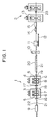
- a continuous hot strip rolling system includes a roughing train 1 and a finishing train 2.
- the roughing train 1 has two two-high twin-roll arranged stands 3, 4 of Nos. 1 and 2 disposed in series.
- two pairs of work rolls 5 and 6 driven by motors of driving devices (not shown) are provided.
- Bearing boxes for the work rolls 5 and 6 are fitted in the window portions of each of common housing assemblies 7, 8.
- Each pair of work rolls 5 and 6 constitutes a two-high mill.
- the roughing train 1 of this embodiment includes four two-high mills which are disposed in series.
- the four two-high mills made up of the four pairs of work rolls 5 and 6 are disposed close to each other so as to provide tandem rolling in which the materials to be rolled are subjected to simultaneous rolling by the two adjoining mills.
- a width press 9 for changing the width of a slab by a press is disposed upstream of the entrance of the twin-roll arranged No. 1 stand 3, and a shear 10 for cutting the leading and trailing ends of the bar being moved and a travelling joining machine 11 for joining the trailing end of the preceding bar to the leading end of the subsequent bar are disposed downstream of the twin-roll arranged No. 2 stand 4.
- the travelling joining machine 11 is made movable along rails 12. Downstream of the joining machine 11, a descaling device 14 for removing the scale on the surface of the bar and an edge heater 15 for heating the edge surfaces of the bar are disposed near the entrance of a No. 1 mill stand 13 of the finishing train 2.
- the finishing train 2 is made up of seven or eight stands not shown, including the No. 1 stand 13.
- Descaling devices 16 and 17 are respectively disposed at the entrance of the twin-roll arranged stands 3 and 4. The descaling devices will be described later in detail.
- Non-driven roll edgers 18 and 19 are respectively disposed at the exit of the twin-roll arranged stands 3 and 4. Between the twin-roll arranged stand 4 and the shear 10 is disposed a heat insulating cover 20.
- Reference numeral 21 denotes a table roller; 22: a slab to be rolled; 23: a roll edger for the finishing No. 2 mill stand.
- the leading end of the slab 22 is brought into contact with the trailing end of the preceding slab so that the preceding slab can be urged forward by the subsequent slab 22 when rolled.
- the bar 22 passes through the roll edger 18 and the descaling device 17, and is sent to the twin-roll arranged No. 2 stand 4 which reduces the thickness of the bar to about 80 mm by the two pairs of work rolls 5 and 6. At this time, the leading end of the bar 22 is brought into contact with the trailing end of the preceding bar so that the preceding bar can be urged forward by the subsequent bar 22 when rolled, as in the case of the twin-roll arranged stand 3.
- the bar fed out of the twin-roll arranged stand 4 passes through the heat insulating cover 20 provided to reduce the temperature reduction and hence reduce the temperature difference over the entire length of the bar, and the leading end of the bar and then the trailing end thereof are cut by the shear 10. Thereafter, the leading end of the bar is joined to the trailing end of the preceding bar by the joining machine 11 which is moved synchronously with the bar. After completion of the joining, the joining machine 11 is driven by a hydraulic cylinder or a motor not shown to be returned to its original position.
- the joined bars pass through the descaling device 14 provided at the entrance of the finishing train 2 to remove the scale on the surface of the bar, and then the edge heater 15 for heating the edges of the bar so as to reduce variations in the temperature, and are then fed to the finishing train 2 for finish rolling.
- the order in which the descaling device 14 and the edge heater 15 are disposed may be reversed.
- the descaling devices 16 and 17 each have upper and lower nozzles 30 one for each.
- the nozzle 30 is mounted on a movable frame 31 which is movable in the direction transverse to the direction of travel of the slab 22 along a guide 32.
- the movable frame 31 has a rack 33 which is in mesh with a pinion 35.
- the movable frame 31 travels when the pinion 35 is driven by a driving motor 34 and the rack 33 is thereby moved.
- the guide 32 is pivotaly supported by a base 36.
- a cylinder 37 is coupled to the front end of the guide 32.
- the driving motor 34 When the driving motor 34 is driven after the guide 32 is oriented in the direction indicated by (a) by the cylinder 37, the nozzle 30 proceeds in the direction indicated by (a) along the guide 32, and the water ejected from the nozzle 30 under high pressure against the slab 22 in the form indicated by C in Fig. 2 is correspondingly moved in the area indicated by (a) in Fig. 5.
- the guide 32 When the nozzle 30 reaches the opposite end portion of the slab 22, the guide 32 is pivoted about the base 36 in the direction indicated by X1 by the cylinder 37 to orient the guide 32 in the direction indicated by (b). Concurrently with this pivoting, the driving motor 34 is driven in a reverse direction to return the nozzle 30 in the direction indicated by (b).
- the roughing train 1 having the two-high mills 5 and 6 rolls the slab to a thickness of about 80 mm.
- generation of camber is greatly reduced as compared with rolling by the four-high mill stands, and stable joining continuous rolling is made possible. Consequently, rolling of thin strips can be performed without problems in feeding the thin strips, and rolling at a high rolling reduction can be performed at the final stand by performing lubricating and tension rolling. These enable strips having a metallurgically excellent quality to be manufactured.
- all the four two-high mills 5 and 6 of the roughing train 1 are disposed close to each other for tandem rolling so that the adjoining mills are subjected to simultaneous rolling, and the bar is roughly rolled to a thickness of about 80 mm. Consequently, the length of the roughing train can be reduced.
- the four two-high mills are constituted by the two twin-roll arranged stands 3 and 4, the two-high mills can be disposed closest to each other, thus greatly reducing the overall length of the roughing rolling line. As a result, the distance between the entrance of the roughing train to the finishing train can be reduced by 200 m or more, and construction cost can thus be reduced greatly.
- control of the temperature of the material to be rolled is essential.
- the slab is rolled to a thick bar of about 80 mm, as stated above, reduction in the temperature of the bar is lessened.
- the two-high mills 5 and 6 are disposed close to each other, the distance between the roughing train 1 and the finishing train 2 can be reduced to one twice that of the conventional rolling system or less, so that the time in which the material to be rolled is cooled uselessly in the rough rolling process can be reduced.
- reduction in the temperature of the bar which occurs until the bar reaches the joining position is lessened, and non-uniformity of the temperature of the bar at the joining position is thus reduced. This enables stable joining continuous rolling as well and manufacture of high-quality products.
- twin-roll arranged stands 3 and 4 are used as the two-high mills, installation cost can be greatly reduced as compared with manufacture of separate mill stands, because the two roll exchangers can be combined.
- the conventional roughing mill is driven by a synchronous motor
- a d.c. motor or an a.c. variable speed motor must be used in this embodiment, because it performs tandem rolling.
- the output of the motor can be reduced in proportion to the rolling rate.
- low speed rolling reduces the rate of strain of the material to be rolled, and thus reduces deformation resistance to about 20%. Consequently, the amount of power for the system can be greatly reduced, and the power consumption can be reduced.
- the use of the conventional descaling device may cause excessive cooling of the slab.
- descaling suitable to the moving speed of the slab 22 can be conducted by moving the nozzle 30 for each of the two surfaces of the slab in the direction transverse to the direction of travel of the slab 22, descaling without excessive cooling can be performed. Also, power of the motor for the descaling pump can be saved.
- the leading end of the subsequent material to be rolled is brought into contact with the trailing end of the preceding material to be rolled so that the preceding material can be pushed forward by the subsequent material when rolled.
- the rolling draft can be increased.
- the twin-roll arranged No. 1 stand 3 produces a sufficient amount of pushing force for pushing the material to be rolled into the twin-roll arranged No. 2 stand 4, the reduction draft at the twin-roll arranged No. 2 stand 4 can further be increased due to the pushing force exerted by the twin-roll arranged No. 1 stand 3.
- slabs are generally manufactured by the continuous casting.
- the slabs manufactured by the continuous casting have a drawback in that it is difficult to change the width thereof.
- the width press 9 is provided near the entrance of the roughing train 1, even when the slabs fed from the continuous casting system are rolled, the width of the slabs can be adjusted without reducing the yield. Since the slab width can be adjusted by the width press 9, the operation of the roll edgers 18 and 19 can be alleviated. Also, since the twin-roll arranged stands 3 and 4 produce a sufficient amount of force for pushing the bar forward, driving of the roll edgers 18 and 19 is not necessary. This particularly applies to the roll edger 18 between the stands 3 and 4.
- the roll edger Since the roll edger is of the vertically driven type, it requires an expensive driving device. Therefore, in this embodiment, since it is not necessary to drive the roll edgers 18 and 19, the system operation cost can be greatly reduced and the maintenance thereof can be improved. Use of the roll edgers of the non-driven type also makes it possible to prevent generation of camber. It is, however, to be noted that the downstream roll edger 19 may be driven in order to conduct fine adjustment of the slab width without generating buckling.
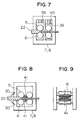
- Fig. 7 shows a modification of the twin-roll arranged stand used in this embodiment.
- the bearing boxes for supporting the upstream work rolls 5 and 6 is supported by the housing assembly 7 or 8 in such a manner as to be slidable in the vertical direction relative to the bearing boxes for supporting the adjacent downstream work rolls.
- this structure increases the width of the window portion, and therefore, to assure the mill rigidity, the cross-sectional areas of the posts and those of the beams of the housing assembly 7 or 8 must be increased.
- an intermediate post 38 is provided between the two pairs of work rolls 5 and 6 in each of the window portions of the housing assembly 7 or 8, as shown in Fig. 7. Consequently, the cross-sectional areas of the posts and those of the beams of the housing assembly can be reduced, and installation cost can thus be reduced.
- Figs. 8 and 9 show another modification of the twin-roll arranged stand used in the present invention.
- the rolling rate at the entrance of the roughing train 1 is very low.
- the rate at which the slabs having a thickness of, for example, 220 mm are supplied to the roughing train is 11 m/min. Accordingly, the speed at which the material to be rolled is moved in the twin-roll arranged stand is low.
- descaling devices 30 are provided at the entrance of each of the twin-roll arranged stands 7 and 8, and inactive gas ejecting devices 41 for ejecting an inactive gas, such as nitrogen, to cover the material to be rolled 22 are disposed between the upstream and downstream work rolls 5 and 6 in each of the twin-roll arranged stands 7 and 8. Consequently, scale can be removed by the descaling devices 30 at the entrance of the twin-roll arranged stand 7 or 8, and generation of the oxidation scale can be prevented by the inactive gas ejecting devices 41 between the upstream and downstream work rolls in the twin-roll arranged stand 7 or 8. Adjacent provision of the work rolls is also enabled.
- This modification is advantageous to prevent generation of oxidation scale on the surface of a common steel.
- steels such as a stainless steel
- provision of the inactive gas ejecting devices 41 can be eliminated.
- the present invention has the following advantages.
Landscapes
- Engineering & Computer Science (AREA)
- Mechanical Engineering (AREA)
- Metal Rolling (AREA)
Applications Claiming Priority (2)
| Application Number | Priority Date | Filing Date | Title |
|---|---|---|---|
| JP303140/90 | 1990-11-08 | ||
| JP30314090 | 1990-11-08 |
Publications (2)
| Publication Number | Publication Date |
|---|---|
| EP0484882A1 true EP0484882A1 (de) | 1992-05-13 |
| EP0484882B1 EP0484882B1 (de) | 1996-02-07 |
Family
ID=17917364
Family Applications (1)
| Application Number | Title | Priority Date | Filing Date |
|---|---|---|---|
| EP91118839A Expired - Lifetime EP0484882B1 (de) | 1990-11-08 | 1991-11-05 | Kontinuierliches Warmband-Walzsystem |
Country Status (3)
| Country | Link |
|---|---|
| US (1) | US5219114A (de) |
| EP (1) | EP0484882B1 (de) |
| DE (1) | DE69116981T2 (de) |
Cited By (8)
| Publication number | Priority date | Publication date | Assignee | Title |
|---|---|---|---|---|
| EP0553480A2 (de) * | 1991-12-27 | 1993-08-04 | Hitachi, Ltd. | Walzwerk, Walzverfahren und Walzwerksystem |
| EP0586823A2 (de) * | 1992-07-31 | 1994-03-16 | DANIELI & C. OFFICINE MECCANICHE S.p.A. | Wasser verwendende Entzunderungsvorrichtung |
| EP0615793A2 (de) * | 1993-03-18 | 1994-09-21 | Hitachi, Ltd. | Warmwalzwerk für Stahlblech und Walzverfahren |
| EP0647484A1 (de) * | 1993-10-07 | 1995-04-12 | Kawasaki Steel Corporation | Verfahren zum Walzen und Schneiden eines kontinuierlich warmgewalzten Stahlbandes |
| CN1047110C (zh) * | 1994-05-17 | 1999-12-08 | 株式会社日立制作所 | 与连续铸造机联机的热轧设备及其轧制方法 |
| KR100434847B1 (ko) * | 1995-09-06 | 2004-08-09 | 에스엠에스 데마그 악티엔게젤샤프트 | 박판압연스트립을압연하기위한열간스트립생산설비 |
| DE4337287B4 (de) * | 1993-11-02 | 2004-08-26 | Sms Demag Ag | Verfahren zur Entzunderung von Walzgut wie Brammen, Dünnbrammen, Warmband oder Vorband und Vorrichtung zur Durchführung des Verfahrens |
| RU2470722C1 (ru) * | 2011-07-14 | 2012-12-27 | Учреждение Российской академии наук Институт металлургии и материаловедения им. А.А. Байкова РАН | Способ прокатки металлической полосы |
Families Citing this family (18)
| Publication number | Priority date | Publication date | Assignee | Title |
|---|---|---|---|---|
| WO1994016838A1 (en) * | 1993-01-28 | 1994-08-04 | Nippon Steel Corporation | Continuous hot rolling method and rolled material joining apparatus |
| JP3254067B2 (ja) * | 1993-05-07 | 2002-02-04 | 川崎製鉄株式会社 | エンドレス圧延における板クラウンの制御方法 |
| US5632177A (en) * | 1994-03-01 | 1997-05-27 | Hitachi, Ltd. | System and method for manufacturing thin plate by hot working |
| US5651412A (en) * | 1995-10-06 | 1997-07-29 | Armco Inc. | Strip casting with fluxing agent applied to casting roll |
| US5661884A (en) * | 1996-02-20 | 1997-09-02 | Tippins Incorporated | Offset high-pressure water descaling system |
| KR100244904B1 (ko) * | 1996-03-04 | 2000-03-02 | 아사무라 타카싯 | 연속 열간 압연방법 |
| US6286354B1 (en) * | 1996-04-03 | 2001-09-11 | Hitachi, Ltd. | Rolling mill and rolling method and rolling equipment |
| IT1288987B1 (it) * | 1996-09-25 | 1998-09-25 | Danieli Off Mecc | Procedimento di saldatura per billette in uscita forno e linea di laminazione adottante detto procedimento |
| IT1316666B1 (it) * | 2000-02-24 | 2003-04-24 | Danieli & C Ohg | Metodo e dispositivo per saldatura |
| US6702525B2 (en) * | 2001-02-28 | 2004-03-09 | Kennametal Inc. | Cutting tool for a bar peeling operation |
| US6976617B2 (en) * | 2002-05-08 | 2005-12-20 | Morgan Construction Company | Uninterrupted continuous rolling of bar and rod products |
| DE10349950A1 (de) * | 2003-10-24 | 2005-05-25 | Sms Demag Ag | Walzwerk zum Warmwalzen von Metall, insbesondere von Aluminium, sowie Warmwalzverfahren |
| TW200927315A (en) * | 2007-10-16 | 2009-07-01 | Ihi Metaltech Co Ltd | Method for magnesium hot rolling and magnesium hot rolling apparatus |
| IT1400002B1 (it) * | 2010-05-10 | 2013-05-09 | Danieli Off Mecc | Procedimento ed impianto per la produzione di prodotti laminati piani |
| DE102012201395A1 (de) * | 2012-02-01 | 2013-08-01 | Sms Siemag Ag | Verfahren zum Stranggießen eines metallischen Stranges in einer Stranggießanlage und Stranggießanlage |
| CN104307881B (zh) * | 2014-10-11 | 2016-08-31 | 中冶天工集团有限公司 | 无缝钢管连轧机轧制中心线调整方法 |
| CN105798067A (zh) * | 2016-04-28 | 2016-07-27 | 中冶天工集团有限公司 | 轧机底座安装精确测量方法 |
| CN113111452B (zh) * | 2021-03-22 | 2023-08-11 | 北京科技大学 | 一种面向热轧带钢的极限规格轧制建议的分析方法 |
Citations (15)
| Publication number | Priority date | Publication date | Assignee | Title |
|---|---|---|---|---|
| US1804111A (en) * | 1929-09-07 | 1931-05-05 | Paterson Alexander | Breakdown mill |
| US1810167A (en) * | 1929-04-10 | 1931-06-16 | Morgan Construction Co | Art of rolling metal |
| DE714111C (de) * | 1938-09-30 | 1941-11-24 | Gustav Wischendorf | Walzwerk zum kontinuierlichen Walzen von Metallbaendern, insbesondere von Breitbaendern |
| DE1652541A1 (de) * | 1968-02-23 | 1971-04-15 | Demag Ag | Verfahren und Vorrichtung zum Herstellen von Grobblechen durch Walzen |
| JPS5095160A (de) * | 1973-12-26 | 1975-07-29 | ||
| JPS50109866A (de) * | 1974-02-08 | 1975-08-29 | ||
| US4294394A (en) * | 1978-08-07 | 1981-10-13 | Hitachi, Ltd. | Method of and apparatus for continuously rolling steel slabs |
| JPS59101204A (ja) * | 1982-11-30 | 1984-06-11 | Sumitomo Metal Ind Ltd | 熱間連続圧延方法 |
| JPS60231504A (ja) * | 1984-04-28 | 1985-11-18 | Mitsubishi Heavy Ind Ltd | 熱間圧延材の接合方法 |
| JPS6117305A (ja) * | 1984-07-03 | 1986-01-25 | Sumitomo Metal Ind Ltd | 強圧下圧延方法 |
| JPS6156708A (ja) * | 1984-08-28 | 1986-03-22 | Sumitomo Metal Ind Ltd | 連続熱間圧延設備列 |
| US4706871A (en) * | 1983-08-12 | 1987-11-17 | Hitachi, Ltd. | Method of continuously hot-rolling steel pieces |
| JPS6368213A (ja) * | 1986-09-08 | 1988-03-28 | Kawasaki Steel Corp | 高圧水デスケ−リングのヘツダ− |
| JPH02235502A (ja) * | 1989-03-06 | 1990-09-18 | Sumitomo Metal Ind Ltd | 熱間連続圧延方法及びその設備 |
| EP0460655A2 (de) * | 1990-06-06 | 1991-12-11 | Hitachi, Ltd. | Verfahren und Vorrichtung zum Verbinden Aneinanderwalzen erwärmten Materials sowie Verfahren zum kontinuerlichen Warmwalzen und Anordnung |
Family Cites Families (11)
| Publication number | Priority date | Publication date | Assignee | Title |
|---|---|---|---|---|
| US3511250A (en) * | 1968-07-25 | 1970-05-12 | United States Steel Corp | Descaling apparatus |
| LU72714A1 (de) * | 1973-07-06 | 1975-10-08 | ||
| US4106318A (en) * | 1974-04-10 | 1978-08-15 | Nippon Steel Corporation | Method and apparatus for rolling metallic material |
| US4384468A (en) * | 1981-09-29 | 1983-05-24 | Tippins Machinery Company, Inc. | Method and apparatus for coiling strip on a hot mill |
| US4444038A (en) * | 1981-09-29 | 1984-04-24 | Tippins Machinery Company, Inc. | Method of modernizing a hot strip mill |
| US4430876A (en) * | 1981-09-29 | 1984-02-14 | Tippins Machinery Company, Inc. | Continuous tandem hot strip mill and method of rolling |
| JPS58112601A (ja) * | 1981-12-25 | 1983-07-05 | Kawasaki Steel Corp | シ−トバ−接合による完全連続圧延配置列 |
| US4502311A (en) * | 1982-12-08 | 1985-03-05 | White Consolidated Industries, Inc. | Apparatus and method for press-edging hot slabs |
| JPS60184481A (ja) * | 1984-03-05 | 1985-09-19 | Mitsubishi Heavy Ind Ltd | 厚肉鋼材の接合方法 |
| JPS60213382A (ja) * | 1984-04-10 | 1985-10-25 | Mitsubishi Heavy Ind Ltd | 厚鋼片の連続熱間圧接方法 |
| JP2522994B2 (ja) * | 1988-07-25 | 1996-08-07 | 株式会社ツーデン | 自動制御装置 |
-
1991
- 1991-11-05 DE DE69116981T patent/DE69116981T2/de not_active Expired - Fee Related
- 1991-11-05 EP EP91118839A patent/EP0484882B1/de not_active Expired - Lifetime
- 1991-11-08 US US07/789,827 patent/US5219114A/en not_active Expired - Fee Related
Patent Citations (15)
| Publication number | Priority date | Publication date | Assignee | Title |
|---|---|---|---|---|
| US1810167A (en) * | 1929-04-10 | 1931-06-16 | Morgan Construction Co | Art of rolling metal |
| US1804111A (en) * | 1929-09-07 | 1931-05-05 | Paterson Alexander | Breakdown mill |
| DE714111C (de) * | 1938-09-30 | 1941-11-24 | Gustav Wischendorf | Walzwerk zum kontinuierlichen Walzen von Metallbaendern, insbesondere von Breitbaendern |
| DE1652541A1 (de) * | 1968-02-23 | 1971-04-15 | Demag Ag | Verfahren und Vorrichtung zum Herstellen von Grobblechen durch Walzen |
| JPS5095160A (de) * | 1973-12-26 | 1975-07-29 | ||
| JPS50109866A (de) * | 1974-02-08 | 1975-08-29 | ||
| US4294394A (en) * | 1978-08-07 | 1981-10-13 | Hitachi, Ltd. | Method of and apparatus for continuously rolling steel slabs |
| JPS59101204A (ja) * | 1982-11-30 | 1984-06-11 | Sumitomo Metal Ind Ltd | 熱間連続圧延方法 |
| US4706871A (en) * | 1983-08-12 | 1987-11-17 | Hitachi, Ltd. | Method of continuously hot-rolling steel pieces |
| JPS60231504A (ja) * | 1984-04-28 | 1985-11-18 | Mitsubishi Heavy Ind Ltd | 熱間圧延材の接合方法 |
| JPS6117305A (ja) * | 1984-07-03 | 1986-01-25 | Sumitomo Metal Ind Ltd | 強圧下圧延方法 |
| JPS6156708A (ja) * | 1984-08-28 | 1986-03-22 | Sumitomo Metal Ind Ltd | 連続熱間圧延設備列 |
| JPS6368213A (ja) * | 1986-09-08 | 1988-03-28 | Kawasaki Steel Corp | 高圧水デスケ−リングのヘツダ− |
| JPH02235502A (ja) * | 1989-03-06 | 1990-09-18 | Sumitomo Metal Ind Ltd | 熱間連続圧延方法及びその設備 |
| EP0460655A2 (de) * | 1990-06-06 | 1991-12-11 | Hitachi, Ltd. | Verfahren und Vorrichtung zum Verbinden Aneinanderwalzen erwärmten Materials sowie Verfahren zum kontinuerlichen Warmwalzen und Anordnung |
Cited By (14)
| Publication number | Priority date | Publication date | Assignee | Title |
|---|---|---|---|---|
| EP0553480A2 (de) * | 1991-12-27 | 1993-08-04 | Hitachi, Ltd. | Walzwerk, Walzverfahren und Walzwerksystem |
| EP0553480B1 (de) * | 1991-12-27 | 1996-03-13 | Hitachi, Ltd. | Walzwerk, Walzverfahren und Walzwerksystem |
| EP0586823A2 (de) * | 1992-07-31 | 1994-03-16 | DANIELI & C. OFFICINE MECCANICHE S.p.A. | Wasser verwendende Entzunderungsvorrichtung |
| EP0586823A3 (en) * | 1992-07-31 | 1994-08-17 | Danieli Off Mecc | Descaling device employing water |
| US5388602A (en) * | 1992-07-31 | 1995-02-14 | Danieli & C. Officine Meccaniche Spa | Descaling device employing water |
| US5636543A (en) * | 1993-03-18 | 1997-06-10 | Hitachi, Ltd. | Hot steel plate rolling mill system and rolling method |
| EP0615793A2 (de) * | 1993-03-18 | 1994-09-21 | Hitachi, Ltd. | Warmwalzwerk für Stahlblech und Walzverfahren |
| EP0615793A3 (de) * | 1993-03-18 | 1995-02-15 | Hitachi Ltd | Warmwalzwerk für Stahlblech und Walzverfahren. |
| EP0647484A1 (de) * | 1993-10-07 | 1995-04-12 | Kawasaki Steel Corporation | Verfahren zum Walzen und Schneiden eines kontinuierlich warmgewalzten Stahlbandes |
| CN1058424C (zh) * | 1993-10-07 | 2000-11-15 | 川崎制铁株式会社 | 无接头热轧钢带的轧制切断方法 |
| DE4337287B4 (de) * | 1993-11-02 | 2004-08-26 | Sms Demag Ag | Verfahren zur Entzunderung von Walzgut wie Brammen, Dünnbrammen, Warmband oder Vorband und Vorrichtung zur Durchführung des Verfahrens |
| CN1047110C (zh) * | 1994-05-17 | 1999-12-08 | 株式会社日立制作所 | 与连续铸造机联机的热轧设备及其轧制方法 |
| KR100434847B1 (ko) * | 1995-09-06 | 2004-08-09 | 에스엠에스 데마그 악티엔게젤샤프트 | 박판압연스트립을압연하기위한열간스트립생산설비 |
| RU2470722C1 (ru) * | 2011-07-14 | 2012-12-27 | Учреждение Российской академии наук Институт металлургии и материаловедения им. А.А. Байкова РАН | Способ прокатки металлической полосы |
Also Published As
| Publication number | Publication date |
|---|---|
| US5219114A (en) | 1993-06-15 |
| DE69116981T2 (de) | 1996-06-20 |
| DE69116981D1 (de) | 1996-03-21 |
| EP0484882B1 (de) | 1996-02-07 |
Similar Documents
| Publication | Publication Date | Title |
|---|---|---|
| EP0484882B1 (de) | Kontinuierliches Warmband-Walzsystem | |
| US6832432B2 (en) | Hot-rolling mill | |
| JP2538153B2 (ja) | 熱間圧延から冷間圧延への転換のための連続処理ライン | |
| EP0510147B1 (de) | System und verfahren zum formen dünner flacher warmgewalzter metallbänder | |
| EP0795361B1 (de) | Verfahren zum kontinuierlichen Walzen von Blechen und/oder Bänder und entsprechende kontinuierliche Walzstrasse | |
| US4086801A (en) | H-shape metallic material rolling process | |
| JPH07308701A (ja) | 連鋳直結熱間圧延設備およびその圧延方法 | |
| JP2528808B2 (ja) | 鋼片の連続熱間圧延方法 | |
| LT3832B (en) | Method for obtaining of steel tape by hot rolling, tape device for pouring out | |
| US3331232A (en) | Method for rolling strip metal | |
| EP0665296A1 (de) | Verfahren und Anlage zum Herstellen warmgewalzter Stahlbänder | |
| US5689991A (en) | Process and device for producing hot-rolled steel strip | |
| JP3119692B2 (ja) | 連続式熱間帯鋼圧延設備及び圧延方法 | |
| JPH10175001A (ja) | 熱間圧延設備及び熱間圧延方法 | |
| JP4339936B2 (ja) | 平鋼を圧延するための圧延ラインおよびこの圧延ラインにより圧延作業を行う方法 | |
| JP3067619B2 (ja) | 連続鋳造圧延設備 | |
| JP3156462B2 (ja) | 熱間圧延設備 | |
| JP2626642B2 (ja) | 鋼片の連続熱間圧延方法 | |
| JPH0780508A (ja) | 鋳造熱間圧延連続設備 | |
| JPH0775721B2 (ja) | 中小形条鋼類の製造設備 | |
| JPH05161902A (ja) | 熱間圧延設備 | |
| JPH10192909A (ja) | 熱間圧延設備及び熱間圧延方法 | |
| JPH0829327B2 (ja) | 熱延鋼板の高速切断方法 | |
| JP2911585B2 (ja) | ホットストリップ圧延設備及び圧延方法 | |
| JPH10265843A (ja) | ステンレス鋼板の製造方法 |
Legal Events
| Date | Code | Title | Description |
|---|---|---|---|
| PUAI | Public reference made under article 153(3) epc to a published international application that has entered the european phase |
Free format text: ORIGINAL CODE: 0009012 |
|
| AK | Designated contracting states |
Kind code of ref document: A1 Designated state(s): DE GB |
|
| 17P | Request for examination filed |
Effective date: 19920518 |
|
| 17Q | First examination report despatched |
Effective date: 19931116 |
|
| GRAA | (expected) grant |
Free format text: ORIGINAL CODE: 0009210 |
|
| AK | Designated contracting states |
Kind code of ref document: B1 Designated state(s): DE GB |
|
| REF | Corresponds to: |
Ref document number: 69116981 Country of ref document: DE Date of ref document: 19960321 |
|
| PLBE | No opposition filed within time limit |
Free format text: ORIGINAL CODE: 0009261 |
|
| STAA | Information on the status of an ep patent application or granted ep patent |
Free format text: STATUS: NO OPPOSITION FILED WITHIN TIME LIMIT |
|
| 26N | No opposition filed | ||
| REG | Reference to a national code |
Ref country code: GB Ref legal event code: IF02 |
|
| PGFP | Annual fee paid to national office [announced via postgrant information from national office to epo] |
Ref country code: GB Payment date: 20021029 Year of fee payment: 12 |
|
| PGFP | Annual fee paid to national office [announced via postgrant information from national office to epo] |
Ref country code: DE Payment date: 20021205 Year of fee payment: 12 |
|
| PG25 | Lapsed in a contracting state [announced via postgrant information from national office to epo] |
Ref country code: GB Free format text: LAPSE BECAUSE OF NON-PAYMENT OF DUE FEES Effective date: 20031105 |
|
| PG25 | Lapsed in a contracting state [announced via postgrant information from national office to epo] |
Ref country code: DE Free format text: LAPSE BECAUSE OF NON-PAYMENT OF DUE FEES Effective date: 20040602 |
|
| GBPC | Gb: european patent ceased through non-payment of renewal fee |
Effective date: 20031105 |