EP0481252A1 - Spreading device - Google Patents
Spreading device Download PDFInfo
- Publication number
- EP0481252A1 EP0481252A1 EP91116299A EP91116299A EP0481252A1 EP 0481252 A1 EP0481252 A1 EP 0481252A1 EP 91116299 A EP91116299 A EP 91116299A EP 91116299 A EP91116299 A EP 91116299A EP 0481252 A1 EP0481252 A1 EP 0481252A1
- Authority
- EP
- European Patent Office
- Prior art keywords
- grit
- chamber
- loading bridge
- spreading
- wall
- Prior art date
- Legal status (The legal status is an assumption and is not a legal conclusion. Google has not performed a legal analysis and makes no representation as to the accuracy of the status listed.)
- Granted
Links
- 239000000463 material Substances 0.000 claims description 53
- 238000005192 partition Methods 0.000 claims description 8
- 238000007599 discharging Methods 0.000 claims 1
- 238000003756 stirring Methods 0.000 claims 1
- 150000003839 salts Chemical class 0.000 description 3
- 230000005484 gravity Effects 0.000 description 2
- 238000000034 method Methods 0.000 description 2
- 239000004576 sand Substances 0.000 description 2
- 244000035744 Hura crepitans Species 0.000 description 1
- 238000010276 construction Methods 0.000 description 1
- 230000001419 dependent effect Effects 0.000 description 1
- 238000000151 deposition Methods 0.000 description 1
- 230000010354 integration Effects 0.000 description 1
- 230000000717 retained effect Effects 0.000 description 1
- 239000000725 suspension Substances 0.000 description 1
Images


Classifications
-
- E—FIXED CONSTRUCTIONS
- E01—CONSTRUCTION OF ROADS, RAILWAYS, OR BRIDGES
- E01C—CONSTRUCTION OF, OR SURFACES FOR, ROADS, SPORTS GROUNDS, OR THE LIKE; MACHINES OR AUXILIARY TOOLS FOR CONSTRUCTION OR REPAIR
- E01C19/00—Machines, tools or auxiliary devices for preparing or distributing paving materials, for working the placed materials, or for forming, consolidating, or finishing the paving
- E01C19/12—Machines, tools or auxiliary devices for preparing or distributing paving materials, for working the placed materials, or for forming, consolidating, or finishing the paving for distributing granular or liquid materials
- E01C19/20—Apparatus for distributing, e.g. spreading, granular or pulverulent materials, e.g. sand, gravel, salt, dry binders
- E01C19/201—Apparatus for distributing, e.g. spreading, granular or pulverulent materials, e.g. sand, gravel, salt, dry binders with driven loosening, discharging or spreading parts, e.g. power-driven, drive derived from road-wheels
- E01C19/202—Apparatus for distributing, e.g. spreading, granular or pulverulent materials, e.g. sand, gravel, salt, dry binders with driven loosening, discharging or spreading parts, e.g. power-driven, drive derived from road-wheels solely rotating, e.g. discharging and spreading drums
- E01C19/203—Centrifugal spreaders with substantially vertical axis
-
- E—FIXED CONSTRUCTIONS
- E01—CONSTRUCTION OF ROADS, RAILWAYS, OR BRIDGES
- E01H—STREET CLEANING; CLEANING OF PERMANENT WAYS; CLEANING BEACHES; DISPERSING OR PREVENTING FOG IN GENERAL CLEANING STREET OR RAILWAY FURNITURE OR TUNNEL WALLS
- E01H10/00—Improving gripping of ice-bound or other slippery traffic surfaces, e.g. using gritting or thawing materials ; Roadside storage of gritting or solid thawing materials; Permanently installed devices for applying gritting or thawing materials; Mobile apparatus specially adapted for treating wintry roads by applying liquid, semi-liquid or granular materials
- E01H10/007—Mobile apparatus specially adapted for preparing or applying liquid or semi-liquid thawing material or spreading granular material on wintry roads
Definitions
- the invention relates to a spreading device according to the preamble of claim 1.
- Spreading devices are known in which a funnel-shaped spreading material container is placed on the loading bridge, from which the spreading material is fed to the spreading material dispensing device, in particular to a spreading material plate, via a spreading material conveying device.
- container spreader devices of the generic type are known, in which the generally funnel-shaped grit container is attached to the carrier vehicle at the rear end of the loading bridge and the grit container is filled batchwise by tilting the loading bridge of the carrier vehicle to the rear.
- Such known grit containers are independent, independent of the loading bridge of the gritting vehicle and have the disadvantage that it is necessary to completely empty the container, all the grit in the grit container on the grit spreading, which takes considerable time, because with conventional spreading devices the construction takes up the entire loading area and the assembly and disassembly is time-consuming. If the dock leveler is quickly needed for other uses, this will result in the vehicle not being ready for those other uses.
- the object of the invention is to provide a spreading device with a conventional spreading material dispensing device, e.g. To design the spreading disc arrangement so that emptying of the spreading material container is practically possible without a time delay, regardless of the degree of filling, and at the same time the functionality of the spreading device is not influenced. Furthermore, the holding capacity of the spreading material in the spreading device should be as large as possible and at the same time the center of gravity of the filled spreading material container should be as low as possible. Furthermore, the use of a double scattering chamber should be provided in a simple and economical way.
- the spreading material is loaded on the entire surface of the loading bridge and brought in a simple manner with the least technical effort directly from the loading bridge of the vehicle by means of a screw conveyor or the like to the rear to the spreading material dispensing device (spreading plate) and thus an extremely large loading volume long stretches can be carried.
- the unused grit can be tipped backwards or sideways regardless of the level of filling of the loading bridge practically, quickly and easily, so that the grit chamber or the loading bridge can be completely emptied in a very short time without the grit first having to pass through the grit delivery device , which would take a considerable amount of time and without the need to dismantle a grit container.
- the loading bridge Due to the extremely fast emptying of the spreading material chamber, the loading bridge can be released very quickly and the vehicle can be used for other purposes within a very short time. Furthermore, the use of the loading bridge as a grit container or the integration of the grit container in the loading bridge means that a separate and independent grit container, as is required in conventional devices, is no longer required, and that the center of gravity of the entire spreading device is also included Spreading material can be placed extremely low, which is essential for the driving behavior of the carrier vehicle, especially in winter operation, since when starting off, braking and cornering, there is no or only negligible tendency to tip backwards, forwards or to the side.
- the spreading device is attached on one side of the loading bridge to one side wall (either the right or the left) assigned.
- the grit chamber can either take up a fraction of the width or the entire width of the loading bridge; in the latter case, the opposite side wall of the loading bridge is the other side wall of the grit chamber.
- the spreading device is provided with an intermediate wall which runs parallel to the side wall of the loading bridge and which faces the interior of the loading bridge, so that the scattering chamber is formed between these two side walls and occupies an adjustable part of the loading bridge width.
- This partition can be firmly connected to the bottom of the grit container, but it can also be slidably formed on the bottom of the loading bridge in the manner of a drawer, so that the width of the remaining part of the loading bridge varies in reverse proportion to the change in the width of the scattering chamber can be.
- the emptying of the loading bridge or the volume of the loading bridge, which is separated by the partition from the grit chamber, is done in such a way that the corresponding side wall is folded down and the loading bridge is tilted about its longitudinal axis, so that the material on the loading bridge is optionally complete or partially tipped over the full length of the dock leveler.
- Such tipping of the material can also be done by tilting the drawer bridge to the rear, if the replacement side wall connected to the back of the grit container, which closes off the remaining part of the loading bridge, is removed.
- the grit chamber itself is designed so that its side wall has a wall part which is pivotally attached directly to the bottom of the grit chamber or to the bottom wall of the loading bridge, and which is open, e.g. can be folded down so that the material can be discharged from the grit chamber when the drop side is folded down if the loading bridge is tilted accordingly about its central longitudinal axis.
- a complete emptying of the spreading material chamber is then possible in the shortest possible time without the spreading material having to pass through the spreading material dispensing device.
- Such emptying of the spreading material chamber is necessary if the spreading device is to be removed from the loading bridge, or if the loading bridge or the carrier vehicle is required in full for other purposes.
- a double-chamber spreading device on the loading bridge, namely two spreading devices arranged next to one another.
- the two grit chambers are placed side by side, the open side of the left chamber being delimited by the side wall of the right chamber and the right chamber by the right side wall of the loading bridge, or vice versa.
- one chamber generally receives road salt and the other chamber split, sand or the like, the split chamber usually being significantly larger in volume than the salt chamber.
- both chambers have separate screw conveyors, but preferably have a common spreading disc instead of two independent spreading discs, a slide, chute or the like then being directed away from the outlet openings of the two spreading material chambers to the receiving device of the common spreading disc.
- This material pick-up device is designed so that a tilting of the loading bridge with the two grit chambers does not affect the functioning, for this purpose the slide or bulk parts can be moved relative to one another, e.g. be telescopic in order to compensate for the different altitudes when tilting.
- one or both chambers can also each have a belt conveyor device for delivering material to the spreading plate.
- the spreading material spreading device or the spreading plate is fastened to the rear wall of the spreading material device or to the floor or frame of the loading bridge.
- the arrangement is chosen so that the connection with the holder of the spreading plate is pivotable, such that when the loading bridge tipping shaft and spreading plate maintain their working position, namely the fixed assignment to the vehicle frame or level of the spreading plate parallel to the ground. This necessitates a corresponding guidance of the spreading plate shaft relative to the loading bridge or an articulated suspension of the spreading plate on the loading bridge and, at the same time, a firm connection of the spreading plate screen to the vehicle frame.
- the spreader plate is attached to the stationary frame of the vehicle in such a way that it retains its position unchanged regardless of the pivoting or tilting of the loading bridge.
- the spreading plate is attached with its holder to the stationary frame of the vehicle so that it can be easily solved, for. B. via a plug connection with locking.
- the spreading device with spreading disc is only required during the winter months, in the rest of the year the entire spreading device with spreading disc is removed from the vehicle and stored.
- a known, running on wheels transport frame is used, which engages at least two locations on the spreader and raises the spreader, which is connected to the vehicle frame or the loading bridge by quick-release fasteners, and removes it from the vehicle.
- the spreader plate is preferably designed so that it can be folded upwards or is easily detachable from the spreader device.
- the arrangement is selected such that the shaft with the spreading plate is pivoted up about the pivot point G in a plane parallel to the plane of the rear wall, so that in this case the spreading device does not have to be dismantled.
- a funnel-shaped outlet opening on the rear side of the drop side which can be closed by hand or by remote control and which is suitable for the targeted delivery of material, e.g. for depositing split in smaller, portioned piles, e.g. also for filling grit boxes on the roadside.
- a loading bridge of a (not shown) carrier vehicle is designated, which is fastened with a tilting frame 2.
- the bottom of the dock leveler is 3, the side walls 4 and 5.
- the front side wall 6 facing the cab connects the two side walls 4 and 5; the tailgate is removed.
- the spreading device consists of the spreading material chamber 9, the spreading material conveying device 18 and the spreading material dispensing device 21 with spreading plate 22.
- the spreading material chamber is a box-shaped container open at the top with an angled side wall 10, 11, 12, a bottom wall 13, one of the container wall 10, 11, 12 opposite side wall 14, which can be the side wall 5, a front end wall 15 and a rear end wall 16.
- the side wall 14 defines the volume of the grit chamber 9 within the loading volume of the loading bridge.
- the rear of the loading bridge 3, 4, 5 is extended in the plane of the rear wall 16 of the grit chamber by a wall section 17 from the rear wall 16 to the side wall 5, so that the two walls 16 and 17 completely close off the loading bridge to the rear.
- the wall section 17 (replacement rear wall) is detachably connected to the rear wall 16 of the grit chamber and to the side wall 5.
- a scattering material conveying device 18 in the form of a screw conveyor is arranged within the spreading material chamber 9, the axial direction and conveying direction of which run parallel to the central longitudinal axis L of the loading bridge.
- This screw conveyor 18 conveys the grit in the grit chamber 9 backwards to the grit outlet 19 assigned to the auger, to which a slide, chute or the like 20 adjoins, which discharges the grit to the grit dispenser 21, which from the rotating gritter plate 22, the holding device 23, for example is fastened to the rear wall 16 or to the loading bridge 1, and there is a grit holder 24, into which the grit is received from the chute 20 and released directly onto the gritter plate 22.
- a lifting device which is preferably a lifting cylinder, the lifting arm 26 of which is connected to the frame 2 of the loading bridge 3 at its central longitudinal axis L, and which is supported on the vehicle frame.
- the lifting cylinder 25 By extending and retracting the lifting cylinder 25, the loading bridge is tilted about the tilt axis L 'or L ", so that the loading bridge can be emptied either to the left or to the right.
- the left tipping point L" becomes, when tipping to right the right tipping point L 'locked.
- the loading bridge 3 can optionally be tilted backwards (about the transverse axis Q-Q), so that the loading bridge can also be emptied via the rear side if the rear walls 16 and 17 are removed.
- the tilting of the loading bridge to the left is shown schematically in FIG. 3.
- This tipping process is carried out when the loading bridge is completely emptied or, in order for the spreading material to be continuously removed from the spreading material chamber, batch material needs to be refilled from the loading bridge into the spreading material chamber.
- the spreading plate maintains its vertical position
- its holder is articulated to the rear wall of the spreading chamber or to the loading bridge at G (indicated in FIG. 1) and at the same time the spreading plate screen 22 'is fixed to the vehicle frame via a support rod 28 or the like (schematically indicated at 29) so that the entire spreading device 21 (with spreading plate 22, holding device 23 and spreading receptacle 24) maintains its position relative to the vehicle frame and can compensate for the tilting movement of the loading bridge 1.
- the spreading plate 22 is always independent depending on the inclination of the loading bridge spreading material in a constant level parallel to the ground level.
- the spreading part 21-24 is indicated by dashed lines.
- the holder 23 is not articulated to the loading bridge or the rear wall of the spreading chamber 9, but is fixedly connected to the vehicle frame, e.g. plugged onto the vehicle frame 29 and locked by a lock so that when the gritting device is removed from the loading bridge 1, the gritting device 21 is only released from the frame and, since all other connections, e.g. electrical and hydraulic connections to the spreading disc are firmly connected to the other spreading material device, the spreading material device is retained as a whole unit.
- Spreading material plate and grit receiving device can be designed in all embodiments of the invention so that they can be pivoted upwards, so that there are no parts protruding downward beyond the bottom of the device for stowing the grit device, especially since the slide or chute 20 can also be removed can be trained.
- a tilting of the loading bridge to the right is shown schematically. This process is necessary if the entire dock leveler is to be emptied as quickly as possible and the vehicle is to be used for another purpose.
- the right side wall 5 of the loading bridge is opened and the loading bridge is raised in the middle and tilted about the tilt axis 27, so that the entire material M located on the loading bridge can be tipped to the right.
- the spreading device is provided in the form of a double-chamber device with the chambers 9 and 30.
- Each of the two chambers has a separate screw conveyor 18, 31 and separate chutes 20, 32, which are directed into a common grit receiving device 33, from which the grit is discharged onto the common spreading plate 34.
- the spreading plate 34 is detachably connected to the vehicle frame via a schematically indicated holder 35, so that a tilting of the loading bridge has no influence on the position of the spreading plate.
- the spreader plate is connected to the spreader via electrical and hydraulic lines (not shown), so that it is detached from the vehicle frame when necessary and then removed together with the entire spreader.
- the chambers 9 and 30 are separated from one another by a common intermediate wall 36 which can be installed as a fixed intermediate wall or can also be arranged to be movable in order to change the volumes of the two chambers 9 and 30.
- the screw conveyors 18 and 31 are either driven jointly and with different ratios, or separately, and the conveying capacity of the screw conveyors can be adapted to the desired amount of discharge from the chutes 20 and 32.
- a space 37 remains on the loading bridge 1 between the chamber 30 and the right side wall 5, which can be used for any other purposes; however, the chambers 9 and 30 can, if necessary, also jointly take up the entire volume of the loading bridge 1, so that the free volume 37 is eliminated.
- the chambers 9 and 30 are for receiving different materials, eg. B. of salt and split, laid out on a single loading bridge; the volume of the chamber, which is intended to accommodate split, is considerably larger than the volume of the road salt-absorbing chamber.
- the arrangement of the double chamber is selected such that two spreading devices are arranged next to one another on the loading bridge.
- the two scattering chambers are designed as completely independent and independent chambers and the two chambers are placed directly next to one another as separate chambers.
- slides or similar spreading material spreading devices emanate from the two chambers and feed the spreading material to the spreading plate via the spreading material receiving devices.
- the spreader plate 21 with its holder 23 corresponding to that shown in Fig. 1 is pivotally attached to the rear wall of the scattering chamber 9 or optionally with the rear boundary of the loading bridge and to maintain the position via a support rod with the Vehicle frame connected. As shown in FIG.
- the slides 39 and 42 directed towards the common grit receiving device are constructed in two parts or in several parts.
- the two parts 40, 41 and 43, 44 of each slide 39, 42 are designed so that they are telescopically pushed into each other when the loading bridge is tilted, so that a correct delivery of the grit into the grit receiving device is ensured even when the loading bridge is tilted.
- Each of the two slides, chutes or the like 39, 42 can also be composed of many elements which are designed to be displaceable one inside the other, so that, depending on the inclination of the tilted loading bridge, the slides or the like 39, 42 lengthen or shorten accordingly.
- elastic, z. B. accordion-shaped tubes, flexible hose lines or the like can be provided, which ensure the transfer of the grit from the chambers in the grit receiving device.
- the delivery of the grit from the chambers to the grit-receiving device can, however, also be carried out in the manner shown schematically in FIG. 8, namely via a conveyor belt 45, which is arranged directly below the grit-outlet opening of the respective chamber and whose discharge-side end is assigned to the grit-receiving device.
- the conveyor belt 45 is connected to the loading bridge and assumes a correspondingly inclined position when the loading bridge is tilted.
- Such a conveyor belt 45 can optionally also be provided in the preceding embodiments; in the case of double chambers, each of the chambers can be provided with a separate conveyor belt; alternatively, the conveyor belt can, as shown in FIG. 8, be assigned to the chamber which is further away from the grit receiving device, while a slide according to the preceding exemplary embodiments is used in the other chamber.
- the double chamber arrangement 9, 38 is designed such that in the left-hand grit chamber 9 the lower wall section 46, which corresponds to the fixed wall section 12 according to FIG. 1, is designed to be pivotable at 47, so that the wall section 12 of can be folded away from the wall section 46 so that an opening 48 is created, through which the material located in the grit chamber 9 can be released to the outside via the folded-down wall 46.
- This allows the grit chamber 9 to be emptied in the shortest possible time without the grit having to be removed in a time-consuming manner via the screw conveyor.
- FIG. 10 A tilting of the grit in the second grit chamber 38 is shown schematically in FIG. 10. Similar to the embodiment according to FIG. 4, the right side wall 5 is folded down to empty the grit container 38 and the loading bridge is tilted to the right about the tilt axis 27, so that the grit container 38 can be emptied quickly and specifically.
- the two grit chambers 9 and 38 of a double chamber are designed in such a way that a common partition 49 is provided which, as indicated by arrow 50, can be adjusted to the left or right, to change the capacity of the two chambers 9 and 38 depending on each other.
- the intermediate wall 49 is firmly connected to a base plate 51 which is adjustably attached to the respective base of the chambers 9 and 38.
- the rear wall of the grit chamber (s) is designed in a special embodiment such that an outer wall of the grit chamber, e.g. the rear wall 16 or an outlet connection 52, e.g. a funnel is attached, through which the spreading material located in the spreading material chamber can be discharged to the outside in the direction of arrow 53.
- an outer wall of the grit chamber e.g. the rear wall 16 or an outlet connection 52, e.g. a funnel
- the opening 54 of the container wall is e.g. Opened and closed again directly by hand using a slide or controlled from the driver's cab using a remote control.
- the screw conveyor 18 or each screw conveyor 18 and 31 can be assigned a known grit loosening device 55 in the form of a stirrer shaft or the like, which consists of a rotating axis with radially outwardly extending wings, fingers or the like, which in the grit within the Act in the grit chamber (s) and prepare the screw conveyor.
- a known grit loosening device 55 in the form of a stirrer shaft or the like, which consists of a rotating axis with radially outwardly extending wings, fingers or the like, which in the grit within the Act in the grit chamber (s) and prepare the screw conveyor.
Abstract
Description
Die Erfindung betrifft eine Streueinrichtung nach dem Oberbegriff des Anspruches 1.The invention relates to a spreading device according to the preamble of
Es sind Streuvorrichtungen bekannt, bei denen ein trichterförmiger Streugutbehälter auf die Ladebrücke aufgesetzt ist, von dem das Streugut über eine Streugutfördervorrichtung der Streugutausbringvorrichtung, insbes. einem Streugutteller zugeführt wird. Des weiteren sind Behälterstreueinrichtungen der gattungsgemäßen Art bekannt, bei denen der in der Regel trichterförmige Streugutbehälter am rückwärtigen Ende der Ladebrücke mit dem Trägerfahrzeug befestigt ist und der Streugutbehälter durch Kippen der Ladebrücke des Trägerfahrzeuges nach hinten absatzweise gefüllt wird.Spreading devices are known in which a funnel-shaped spreading material container is placed on the loading bridge, from which the spreading material is fed to the spreading material dispensing device, in particular to a spreading material plate, via a spreading material conveying device. Furthermore, container spreader devices of the generic type are known, in which the generally funnel-shaped grit container is attached to the carrier vehicle at the rear end of the loading bridge and the grit container is filled batchwise by tilting the loading bridge of the carrier vehicle to the rear.
Derartige bekannte Streugutbehälter sind selbständige, von der Ladebrücke des Streufahrzeuges unabhängige Behälter und haben den Nachteil, daß es zum vollständigen Entleeren des Behälters erforderlich ist, das gesamte, im Streugutbehälter befindliche Streugut über die Streugutausbringung zu führen, was erhebliche Zeit erfordert, weil bei herkömmlichen Streueinrichtungen der Aufbau die gesamte Ladefläche beansprucht und der An- und Abbau zeitaufwendig ist. Wenn die Ladebrücke für andere Einsatzzwecke rasch benötigt wird, führt dies dazu, daß das Fahrzeug für diese anderen Zwecke nicht einsatzbereit ist.Such known grit containers are independent, independent of the loading bridge of the gritting vehicle and have the disadvantage that it is necessary to completely empty the container, all the grit in the grit container on the grit spreading, which takes considerable time, because with conventional spreading devices the construction takes up the entire loading area and the assembly and disassembly is time-consuming. If the dock leveler is quickly needed for other uses, this will result in the vehicle not being ready for those other uses.
Aufgabe der Erfindung ist es, eine Streueinrichtung mit herkömmlicher Streugutausbringvorrichtung, z.B. Streutelleranordnung so auszubilden, daß ein Entleeren des Streugutbehälters unabhängig von dem Befüllungsgrad praktisch ohne Zeitverzögerung möglich ist, und gleichzeitig die Funktionsfähigkeit der Streueinrichtung nicht beeinflußt wird. Des weiteren soll die Aufnahmekapazität an Streugut in der Streueinrichtung möglichst groß sein und gleichzeitig der Schwerpunkt des gefüllten Streugutbehälters möglichst niedrig liegen. Ferner soll der Einsatz einer Doppelstreukammer auf einfache und wirtschaftliche Weise vorgesehen werden.The object of the invention is to provide a spreading device with a conventional spreading material dispensing device, e.g. To design the spreading disc arrangement so that emptying of the spreading material container is practically possible without a time delay, regardless of the degree of filling, and at the same time the functionality of the spreading device is not influenced. Furthermore, the holding capacity of the spreading material in the spreading device should be as large as possible and at the same time the center of gravity of the filled spreading material container should be as low as possible. Furthermore, the use of a double scattering chamber should be provided in a simple and economical way.
Gemäß der Erfindung wird dies mit den Merkmalen des Kennzeichens des Anspruches 1 erreicht. Weitere Ausgestaltungen der Erfindung sind Gegenstand der Unteransprüche.According to the invention, this is achieved with the features of the characterizing part of
Mit der Erfindung wird erreicht, daß das Streugut auf der gesamten Fläche der Ladebrücke geladen und auf einfache Weise mit geringstem technischem Aufwand direkt von der Ladebrücke des Fahrzeuges mittels Förderschnecke oder dergleichen nach hinten zur Streugutausbringvorrichtung (Streuteller) gebracht wird und damit ein extrem großes Ladevolumen über weite Streustrecken mitgeführt werden kann. Das nicht verbrauchte Streugut kann unabhängig vom Befüllungsgrad der Ladebrücke praktisch, schnell und einfach ohne wesentliche Zeitverzögerung nach hinten oder seitlich abgekippt werden, so daß die Streugutkammer bzw. die Ladebrücke in kürzester Zeit vollständig entleert werden kann, ohne daß das Streugut erst die Streugutausbringvorrichtung durchlaufen muß, was mit einem erheblichen Zeitaufwand verbunden wäre, und ohne daß es erforderlich ist, einen Streugutbehälter abzubauen. Dies stellt eine wesentliche Verbesserung gegenüber herkömmlichen Streueinrichtungen dar. Durch die Möglichkeit der extrem schnellen Entleerung der Streugutkammer ist die Ladebrücke sehr schnell freisetzbar und das Fahrzeug nach kürzesterZeit für andere Zwecke einsetzbar. Des weiteren ergibt sich durch die Verwendung der Ladebrücke als Streugutbehälter bzw. die Integrierung des Streugutbehälters in die Ladebrücke, daß ein eigener und selbständiger Streugutbehälter, wie er bei herkömmlichen Einrichtungen erforderlich ist, nicht mehr benötigt wird, und daß damit der Schwerpunkt der gesamten Streueinrichtung mit Streugut extrem tief gelegt werden kann, was für das Fahrverhalten des Trägerfahrzeuges, gerade im Winterbetrieb, von wesentlicher Bedeutung ist, da beim Anfahren, beim Abbremsen und beim Kurvenfahren keine oder nur vernachlässigbare Kippneigungen nach hinten, nach vorne oder zur Seite auftreten können.With the invention it is achieved that the spreading material is loaded on the entire surface of the loading bridge and brought in a simple manner with the least technical effort directly from the loading bridge of the vehicle by means of a screw conveyor or the like to the rear to the spreading material dispensing device (spreading plate) and thus an extremely large loading volume long stretches can be carried. The unused grit can be tipped backwards or sideways regardless of the level of filling of the loading bridge practically, quickly and easily, so that the grit chamber or the loading bridge can be completely emptied in a very short time without the grit first having to pass through the grit delivery device , which would take a considerable amount of time and without the need to dismantle a grit container. This represents a significant improvement compared to conventional spreading devices. Due to the extremely fast emptying of the spreading material chamber, the loading bridge can be released very quickly and the vehicle can be used for other purposes within a very short time. Furthermore, the use of the loading bridge as a grit container or the integration of the grit container in the loading bridge means that a separate and independent grit container, as is required in conventional devices, is no longer required, and that the center of gravity of the entire spreading device is also included Spreading material can be placed extremely low, which is essential for the driving behavior of the carrier vehicle, especially in winter operation, since when starting off, braking and cornering, there is no or only negligible tendency to tip backwards, forwards or to the side.
Bei einer Ausführungsform der Erfindung ist die Streueinrichtung auf einer Seite der Ladebrücke der einen Bordwand (entweder der rechten oder der linken) zugeordnet angebracht. Die Streugutkammer kann dabei wahlweise nur einen Bruchteil der Breite oder die ganze Breite der Ladebrücke einnehmen; in letzterem Fall stellt die gegenüberliegende Seitenwand der Ladebrücke die andere Seitenwand der Streugutkammer dar.In one embodiment of the invention, the spreading device is attached on one side of the loading bridge to one side wall (either the right or the left) assigned. The grit chamber can either take up a fraction of the width or the entire width of the loading bridge; in the latter case, the opposite side wall of the loading bridge is the other side wall of the grit chamber.
Bei einer anderen Ausgestaltung der Erfindung ist die Streueinrichtung mit einer Zwischenwand versehen, die parallel zur Seitenbordwand der Ladebrücke verläuft und die dem Ladebrückeninneren zugewandt ist, so daß die Streukammer zwischen diesen beiden Seitenwänden ausgebildet ist und einen verstellbaren Teil der Ladebrückenbreite einnimmt. Diese Zwischenwand kann mit dem Boden des Streugutbehälters fest verbunden sein, sie kann jedoch auch auf dem Boden der Ladebrücke nach Art einer Schublade verschiebbar ausgebildet sein, so daß mit der Änderung der Breite der Streukammer im umgekehrten Verhältnis auch die Breite des restlichen Teiles der Ladebrücke variiert werden kann.In another embodiment of the invention, the spreading device is provided with an intermediate wall which runs parallel to the side wall of the loading bridge and which faces the interior of the loading bridge, so that the scattering chamber is formed between these two side walls and occupies an adjustable part of the loading bridge width. This partition can be firmly connected to the bottom of the grit container, but it can also be slidably formed on the bottom of the loading bridge in the manner of a drawer, so that the width of the remaining part of the loading bridge varies in reverse proportion to the change in the width of the scattering chamber can be.
Das Entleeren der Ladebrücke bzw. des Volumens der Ladebrücke, das durch die Zwischenwand von der Streugutkammer getrennt ist, geschieht in der Weise, daß die entsprechende Bordwand abgeklappt und die Ladebrücke um ihre Längsachse gekippt wird, so daß das auf der Ladebrücke befindliche Material wahlweise vollständig oder teilweise über die volle Länge der Ladebrücke abgekippt werden kann. Ein derartiges Abkippen des Materiales kann auch durch Kippen der Ladebrücke nach hinten erfolgen, wenn die mit der Rückseite des Streugutbehälters verbundene Ersatzbordwand, die den übrigen Teil der Ladebrücke nach hinten abschließt, entfernt wird.The emptying of the loading bridge or the volume of the loading bridge, which is separated by the partition from the grit chamber, is done in such a way that the corresponding side wall is folded down and the loading bridge is tilted about its longitudinal axis, so that the material on the loading bridge is optionally complete or partially tipped over the full length of the dock leveler. Such tipping of the material can also be done by tilting the drawer bridge to the rear, if the replacement side wall connected to the back of the grit container, which closes off the remaining part of the loading bridge, is removed.
Nach einer anderen Ausführungsform der Erfindung ist die Streugutkammer selbst so ausgebildet, daß ihre Seitenwand einen Wandteil besitzt, der unmittelbar am Boden der Streugutkammer bzw. an der Bodenwand der Ladebrücke schwenkbar befestigt ist, und der geöffnet, z.B. abgeklappt werden kann, so daß das Material aus der Streugutkammer bei abgeklappter Bordwand abgegeben werden kann, wenn die Ladebrücke um ihre Mittenlängsachse entsprechend gekippt wird. Damit ist dann ein vollständiges Entleeren der Streugutkammer in kürzester Zeit möglich, ohne daß das Streugut die Streugutausbringvorrichtung durchlaufen muß. Ein derartiges Entleeren der Streugutkammer ist erforderlich, wenn die Streueinrichtung von der Ladebrücke abgebaut werden soll, oder die Ladebrücke bzw. das Trägerfahrzeug voll zu anderen Zwecken benötigt wird.According to another embodiment of the invention, the grit chamber itself is designed so that its side wall has a wall part which is pivotally attached directly to the bottom of the grit chamber or to the bottom wall of the loading bridge, and which is open, e.g. can be folded down so that the material can be discharged from the grit chamber when the drop side is folded down if the loading bridge is tilted accordingly about its central longitudinal axis. A complete emptying of the spreading material chamber is then possible in the shortest possible time without the spreading material having to pass through the spreading material dispensing device. Such emptying of the spreading material chamber is necessary if the spreading device is to be removed from the loading bridge, or if the loading bridge or the carrier vehicle is required in full for other purposes.
In weiterer Ausgestaltung der Erfindung wird vorgeschlagen, auf der Ladebrücke eine Doppelkammer-Streuguteinrichtung vorzusehen, nämlich zwei nebeneinander angeordnete Streueinrichtungen. Hierbei sind die beiden Streugutkammern seitlich aneinandergesetzt, wobei die offene Seite der linken Kammer durch die Seitenwand der rechten Kammer und die rechte Kammer durch die rechte Bordwand der Ladebrücke begrenzt wird, oder umgekehrt. Bei derartigen Doppelkammern nimmt in der Regel die eine Kammer Streusalz und die andere Kammer Split, Sand oder dergl. auf, wobei die Splitkammer üblicherweise im Volumen wesentlich größer ist als die Salzkammer. Beide Kammern haben bei allen Ausführungsformen getrennte Förderschnecken, haben jedoch vorzugsweise an Stelle von zwei unabhängigen Streutellern einen gemeinsamen Streuteller, wobei dann von den Austrittsöffnungen der beiden Streugutkammern weg jeweils eine Rutsche, Schütte oder dergl. zur Gutaufnahmevorrichtung des gemeinsamen Streutellers gerichtet ist. Diese Gutaufnahmevorrichtung ist so ausgebildet, daß ein Kippen der Ladebrücke mit den beiden Streugutkammern die Funktionsweise nicht beeinflußt, hierzu können die Rutschen- oder Schüttenteile zueinander verschiebbar, z.B. teleskopförmig ausgebildet sein, um einen Ausgleich durch die unterschiedlichen Höhenlagen beim Kippen zu erreichen. Stattdessen können jedoch eine oder beide Kammern auch jeweils eine Bandfördervorrichtung zur Materialabgabe an den Streuteller aufweisen.In a further embodiment of the invention, it is proposed to provide a double-chamber spreading device on the loading bridge, namely two spreading devices arranged next to one another. Here, the two grit chambers are placed side by side, the open side of the left chamber being delimited by the side wall of the right chamber and the right chamber by the right side wall of the loading bridge, or vice versa. In the case of double chambers of this type, one chamber generally receives road salt and the other chamber split, sand or the like, the split chamber usually being significantly larger in volume than the salt chamber. In all embodiments, both chambers have separate screw conveyors, but preferably have a common spreading disc instead of two independent spreading discs, a slide, chute or the like then being directed away from the outlet openings of the two spreading material chambers to the receiving device of the common spreading disc. This material pick-up device is designed so that a tilting of the loading bridge with the two grit chambers does not affect the functioning, for this purpose the slide or bulk parts can be moved relative to one another, e.g. be telescopic in order to compensate for the different altitudes when tilting. Instead, however, one or both chambers can also each have a belt conveyor device for delivering material to the spreading plate.
Die Streugutausbringvorrichtung bzw. der Streuteller ist im Falle einer Ausführungsform der Erfindung an der Rückwand der Streuguteinrichtung bzw. am Boden oder Rahmen der Ladebrücke befestigt. Die Anordnung ist dabei so gewählt, daß die Verbindung mit der Halterung der Streutellers schwenkbar ausgebildet ist, derart, daß bei einem Kippen der Ladebrücke Schaft und Streuteller ihre Arbeitsposition beibehalten, nämlich die feste Zuordnung zum Fahrzeugrahmen bzw. Ebene des Streutellers parallel zum Boden. Dies macht eine entsprechende Führung des Streutellerschaftes relativ zur Ladebrücke bzw. eine Gelenkaufhängung des Streutellers an der Ladebrücke sowie gleichzeitig eine feste Verbindung des Streutellerschirmes mit dem Fahrzugrahmen erforderlich. Bei einer anderen Ausführungsform der Erfindung ist der Streuteller am stationären Rahmen des Fahrzeuges so befestigt, daß er seine Position unabhängig vom Verschwenken bzw. Kippen der Ladebrücke unverändert beibehält. Hierzu ist der Streuteller mit seiner Halterung am stationären Rahmen des Fahrzeuges so befestigt, daß er auf einfache Weise gelöst werden kann, z. B. über eine Steckverbindung mit Verriegelung.In the case of an embodiment of the invention, the spreading material spreading device or the spreading plate is fastened to the rear wall of the spreading material device or to the floor or frame of the loading bridge. The arrangement is chosen so that the connection with the holder of the spreading plate is pivotable, such that when the loading bridge tipping shaft and spreading plate maintain their working position, namely the fixed assignment to the vehicle frame or level of the spreading plate parallel to the ground. This necessitates a corresponding guidance of the spreading plate shaft relative to the loading bridge or an articulated suspension of the spreading plate on the loading bridge and, at the same time, a firm connection of the spreading plate screen to the vehicle frame. In another embodiment of the invention, the spreader plate is attached to the stationary frame of the vehicle in such a way that it retains its position unchanged regardless of the pivoting or tilting of the loading bridge. For this purpose, the spreading plate is attached with its holder to the stationary frame of the vehicle so that it can be easily solved, for. B. via a plug connection with locking.
Die Streueinrichtung mit Streuteller wird nur während der Wintermonate benötigt, in der übrigen Zeit des Jahres wird die gesamte Einrichtung mit Streuteller vom Fahrzeug abgenommen und gelagert. Hierfür wird ein an sich bekanntes, auf Rädern laufendes Transportgestell verwendet, das an mindestens zwei Stellen der Streueinrichtung angreift und die Streueinrichtung, die durch Schnellverschlüsse mit dem Fahrzeugrahmen bzw. der Ladebrücke verbunden ist, anhebt und vom Fahrzeug entfernt. Zur einfacheren Lagerung oder auch für einen anderweitigen Betrieb am Fahrzeug ist der Streuteller vorzugsweise so ausgebildet, daß er nach oben klappbar oder von der Streueinrichtung auf einfache Weise lösbar ausgebildet ist. Bei einer Ausführung, bei der der Streuteller bzw. das Streuteil nach oben klappbar ist, ist die Anordnung so gewählt, daß ein Hochschwenken des Schaftes mit Streuteller um den Schwenkpunkt G in einer Ebene parallel zur Ebene der Rückwand vorgenommen wird, so daß in diesem Fall die Streueinrichtung nicht abgebaut werden muß.The spreading device with spreading disc is only required during the winter months, in the rest of the year the entire spreading device with spreading disc is removed from the vehicle and stored. For this purpose, a known, running on wheels transport frame is used, which engages at least two locations on the spreader and raises the spreader, which is connected to the vehicle frame or the loading bridge by quick-release fasteners, and removes it from the vehicle. For easier storage or for other operation on the vehicle, the spreader plate is preferably designed so that it can be folded upwards or is easily detachable from the spreader device. In an embodiment in which the spreading plate or the spreading part can be folded upwards, the arrangement is selected such that the shaft with the spreading plate is pivoted up about the pivot point G in a plane parallel to the plane of the rear wall, so that in this case the spreading device does not have to be dismantled.
Mit einer weiteren Ausführungsform der Erfindung wird vorgeschlagen, an der rückseitigen Ersatzbordwand eine trichterförmige Austrittsöffnung vorzusehen, die von Hand oder durch Fernbedienung verschließbar ist und die zur gezielten Materialabgabe geeignet ist, z.B. zum Absetzen von Split in kleineren, portionierten Haufen, z.B. auch zum Befüllen von Streugutkästen am Straßenrand.With a further embodiment of the invention, it is proposed to provide a funnel-shaped outlet opening on the rear side of the drop side which can be closed by hand or by remote control and which is suitable for the targeted delivery of material, e.g. for depositing split in smaller, portioned piles, e.g. also for filling grit boxes on the roadside.
Nachstehend wird die Erfindung in Verbindung mit der Zeichnung anhand von Ausführungsbeispielen erläutert. Es zeigt:
- Fig. 1 eine Endansicht einer Behälterstreueinrichtung nach der Erfindung, teilweise im Schnitt,
- Fig. 2 eine Seitenansicht der Darstellung nach Fig. 1,
- Fig. 3 in schematischer Darstellung die Behälterstreueinrichtung nach Fig. 1 in nach links nachfüllender oder abkippender Position,
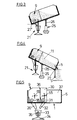
- Fig. 4 die Behälterstreueinrichtung nach Fig. 1 in schematischer Darstellung in nach rechts abkippender Position,
- Fig. 5 eine andere Ausführung der Behälterstreueinrichtung mit Doppelkammer,
- Fig. 6 eine Doppelkammer-Behälterstreueinrichtung in gegenüber Fig. 5 abgeänderter Ausführungsform,
- Fig. 7 die Ausführungsform nach Fig. 6 in nach links nachfüllender oder abkippender Position,
- Fig. 8 die Behälterstreueinrichtung nach Fig. 6 in weiterer abgeänderter Ausführungsform,
- Fig. 9 eine andere Ausführungsform einer Doppelkammer-Behälterstreueinrichtung in nach links abkippender Position aus der linken Kammer,
- Fig. 10 die Ausführungsform nach Fig. 9 in nach rechts abkippender Position aus der rechten Kammer
- Fig. 11 in schematischer Darstellung eine verschiebbare Zwischenwand für eine Doppelkammer,
- Fig. 12 eine schematische Darstellung einer Auslaßöffnung in seitlicher Ansicht, und
- Fig. 13 die Auslaßöffnung nach Fig. 12 in Vorderansicht.
- 1 is an end view of a container spreader according to the invention, partly in section,
- Fig. 2 is a side view of the
illustration 1, - 3 shows a schematic representation of the container spreader device according to FIG. 1 in a refilling or tipping position to the left,
- 4 shows the container spreading device according to FIG. 1 in a schematic representation in a position tipping to the right,
- 5 shows another embodiment of the container spreading device with a double chamber,
- 6 shows a double-chamber container spreader in an embodiment modified from FIG. 5,
- 7 shows the embodiment according to FIG. 6 in the refilling or tipping position to the left,
- 8 shows the container spreader device according to FIG. 6 in a further modified embodiment,
- 9 shows another embodiment of a double-chamber container spreader in the position tipping to the left from the left chamber,
- Fig. 10 shows the embodiment of FIG. 9 in the right-tilted position from the right chamber
- 11 is a schematic representation of a movable partition for a double chamber,
- Fig. 12 is a schematic representation of an outlet opening in a side view, and
- Fig. 13, the outlet opening of FIG. 12 in a front view.
Mit 1 ist eine Ladebrücke eines (nicht dargestellten) Trägerfahrzeuges bezeichnet, die mit einem Kipprahmen 2 befestigt ist. Der Boden der Ladebrücke ist mit 3, die seitlichen Bordwände sind mit 4 und 5 bezeichnet. Die vordere, dem Fahrhaus zugewandte Bordwand 6 verbindet die beiden Seitenbordwände 4 und 5 miteinander; die Bordrückwand ist entfernt.1 with a loading bridge of a (not shown) carrier vehicle is designated, which is fastened with a
Die Streueinrichtung besteht aus der Streugutkammer 9, der Streugutfördervorrichtung 18 und der Streugutausbringvorrichtung 21 mit Streuteller 22. Die Streugutkammer ist ein kastenförmiger, oben offener Behälter mit einer abgewinkelten Seitenwand 10, 11, 12, einer Bodenwand 13, einer der Behälterwand 10, 11, 12 gegenüberliegenden Seitenwand 14, die die Bordwand 5 sein kann, einer vorderen Stirnwand 15 und einer hinteren Stirnwand 16. Die Seitenwand 14 legt das Volumen der Streugutkammer 9 innerhalb des Ladevolumens der Ladebrücke fest. Die Rückseite der Ladebrücke 3, 4, 5 ist in der Ebene der Rückwand 16 der Streugutkammer durch einen Wandabschnitt 17 von der Rückwand 16 bis zur Bordwand 5 verlängert, so daß die beiden Wände 16 und 17 die Ladebrücke nach hinten vollständig abschließen. Der Wandabschnitt 17 (Ersatzrückwand) ist mit der Rückwand 16 der Streugutkammer und mit der Seitenbordwand 5 lösbar verbunden. Innerhalb der Streugutkammer 9 ist eine Streugutfördervorrichtung 18 in Form einer Förderschnecke angeordnet, deren Achsrichtung und Förderrichtung parallel zur Mittenlängsachse L der Ladebrücke verläuft. Diese Förderschnecke 18 fördert das in der Streugutkammer 9 befindliche Streugut nach rückwärts zu dem der Förderschnecke zugeordneten Streugutaustritt 19, an den sich eine Rutsche, Schütte oder dergl. 20 anschließt, die das Streugut an die Streugutausbringvorrichtung 21 abgibt, die aus dem rotierenden Streuteller 22, der Haltevorrichtung 23, die z.B. an der Rückwand 16 oder an der Ladebrücke 1 befestigt ist, und einer Streugutaufnahme 24 besteht, in die das Streugut aus der Rutsche 20 aufgenommen und unmittelbar auf den Streuteller 22 abgegeben wird.The spreading device consists of the spreading
Mit 25 ist eine Hubvorrichtung schematisch dargestellt, die vorzugsweise ein Hubzylinder ist, dessen Hubarm 26 mit dem Rahmen 2 der Ladebrücke 3 an deren Mittenlängsachse L verbunden ist, und die auf dem Fahrzeugrahmen abgestützt ist. Durch Ausfahren und Einziehen des Hubzylinders 25 wird die Ladebrücke um die Kippachse L' oder L" gekippt, so daß die Ladebrücke entweder nach links oder nach rechts entleert werden kann. Bei einem Abkippen nach links wird die linke Kippstelle L", bei einem Abkippen nach rechts die rechte Kippstelle L' verriegelt. Des weiteren ist die Ladebrücke 3 auch wahlweise nach hinten (um die Querachse Q-Q) kippbar, so daß ein Entleeren der Ladebrücke auch über die Rückseite möglich ist, wenn die Rückwände 16 und 17 entfernt werden.25 schematically shows a lifting device, which is preferably a lifting cylinder, the lifting
Das Kippen der Ladebrücke nach links ist schematisch in Fig. 3 dargestellt. Dieser Kippvorgang wird durchgeführt, wenn die Ladebrücke vollständig entleert oder aber für das laufende Ausbringen des Streugutes aus der Streugutkammer Streugutmaterial aus der Ladebrücke in die Streugutkammer absatzweise nachgefüllt werden muß. Damit hierbei der Streuteller seine vertikale Lage beibehält, ist seine Halterung an der Rückwand der Streukammer bzw. an der Ladebrücke gelenkig bei G befestigt (in Fig. 1 angedeutet) und gleichzeitig der Streutellerschirm 22' über eine Haltestange 28 oder dergl. fest mit dem Fahrzeugrahmen (schematisch mit 29 angedeutet) verbunden, so daß die gesamte Streugutausbringvorrichtung 21 (mit Streuteller 22, Haltevorrichtung 23 und Streugutaufnahme 24) ihre Position relativ zum Fahrzeugrahmen beibehält und die Kippbewegung der Ladebrücke 1 ausgleichen kann. Auf diese Weise wird erreicht, daß der Streuteller 22 stets unabhängig von der Neigung der Ladebrücke Streugut in einer gleichbleibenden Ebene parallel zur Bodenebene ausbringt. In Fig. 1 ist der hochgeklappte Streuteil 21 - 24 gestrichelt angedeutet. Zum Hochklappen wird dabei die Haltestange 28 vom Streuteller 22' gelöst und in der hochgeklappten Stellung wird der Schaft 23 bzw. der Streuteller 22 verriegelt.The tilting of the loading bridge to the left is shown schematically in FIG. 3. This tipping process is carried out when the loading bridge is completely emptied or, in order for the spreading material to be continuously removed from the spreading material chamber, batch material needs to be refilled from the loading bridge into the spreading material chamber. So that the spreading plate maintains its vertical position, its holder is articulated to the rear wall of the spreading chamber or to the loading bridge at G (indicated in FIG. 1) and at the same time the spreading plate screen 22 'is fixed to the vehicle frame via a
Bei einer anderen Ausführungsform der Anbringung der Streugutausbringvorrichtung 21 ist die Halterung 23 nicht mit der Ladebrücke bzw. der Rückwand der Streukammer 9 gelenkig befestigt, sondern fest mit dem Fahrzeugrahmen verbunden, z.B. auf den Fahrzeugrahmen 29 aufgesteckt und durch eine Verriegelung gesperrt, so daß beim Abnehmen der Streuguteinrichtung von der Ladebrücke 1 die Streugutausbringvorrichtung 21 lediglich vom Rahmen gelöst wird und, da alle übrigen Verbindungen, z.B. elektrische und hydraulische Verbindungen zum Streuteller mit der übrigen Streuguteinrichtung fest verbunden sind, die Streuguteinrichtung als Gesamteinheit erhalten bleibt. Streugutteller und Streugutaufnahmevorrichtung können dabei bei allen Ausführungsformen der Erfindung so ausgebildet sein, daß sie nach oben geschwenkt werden können, wodurch zum Verstauen der Streuguteinrichtung keine nach unten über den Boden der Einrichtung hinausstehenden Teile mehr vorhanden sind, zumal die Rutsche bzw. Schütte 20 ebenfalls abnehmbar ausgebildet sein kann.In another embodiment of the attachment of the spreading
In Fig. 4 ist ein Kippen der Ladebrücke nach rechts schematisch dargestellt. Dieser Vorgang wird erforderlich, wenn die gesamte Ladebrücke so rasch wie möglich entleert werden soll und das Fahrzeug für einen anderen Zweck einzusetzen ist. In diesem Fall wird die rechte Bordwand 5 der Ladebrücke geöffnet und die Ladebrücke mittig angehoben sowie um die Kippachse 27 gekippt, so daß das gesamte auf der Ladebrücke befindliche Material M nach rechts abgekippt werden kann.In Fig. 4, a tilting of the loading bridge to the right is shown schematically. This process is necessary if the entire dock leveler is to be emptied as quickly as possible and the vehicle is to be used for another purpose. In this case, the
Bei der schematischen Darstellung nach Fig. 5 ist die Streueinrichtung in Form einer Doppelkammereinrichtung mit den Kammern 9 und 30 vorgesehen. Jede der beiden Kammern weist hierbei eine getrennte Förderschnecke 18, 31, sowie getrennte Rutschen 20, 32 auf, die in eine gemeinsame Streugutaufnahmevorrichtung 33 gerichtet sind, von der das Streugut auf den gemeinsamen Streuteller 34 abgegeben wird. Der Streuteller 34 ist über eine schematisch angedeutete Halterung 35 mit dem Fahrzeugrahmen lösbar verbunden, so daß ein Kippen der Ladebrücke ohne Einfluß auf die Position des Streutellers bleibt. Dabei ist der Streuteller mit der Streueinrichtung über elektrische und hydraulische Leitungen (nicht dargestellt) verbunden, so daß er im Bedarfsfall vom Fahrzeugrahmen gelöst und dann zusammen mit der gesamten Streueinrichtung abgenommen wird. Die Kammern 9 und 30 sind durch eine gemeinsame Zwischenwand 36 voneinander getrennt, die als feste Zwischenwand eingebaut oder auch beweglich angeordnet sein kann, um die Volumina der beiden Kammern 9 und 30 zu verändern. Die Förderschnecken 18 und 31 sind entweder gemeinsam und mit unterschiedlicher Übersetzung, oder aber getrennt voneinander angetrieben, und die Förderleistung der Förderschnecken ist der jeweils gewünschten Ausbringmenge aus den Rutschen 20 und 32 anpaßbar. Auf der Ladebrücke 1 verbleibt zwischen Kammer 30 und rechter Bordwand 5 ein Raum 37, der für beliebige andere Zwecke verwendet werden kann; die Kammern 9 und 30 können jedoch erforderlichenfalls gemeinsam auch das gesamte Volumen der Ladebrücke 1 einnehmen, so daß das freie Volumen 37 entfällt. Die Kammern 9 und 30 sind zur Aufnahme unterschiedlicher Materialien, z. B. von Salz und Split, auf einer einzigen Ladebrücke ausgelegt; dabei ist das Volumen der Kammer, die zur Aufnahme von Split bestimmt ist, wesentlich größer als das Volumen der Streusalz aufnehmenden Kammer.5, the spreading device is provided in the form of a double-chamber device with the
Bei der Ausführungsform nach den Figuren 6 und 7 ist die Anordnung der Doppelkammer so gewählt, daß zwei Streueinrichtungen nebeneinander auf der Ladebrücke angeordnet sind. Hierbei sind die beiden Streukammern als völlig selbständige und voneinander unabhängige Kammern ausgebildet und die beiden Kammern als getrennte Kammern unmittelbar aneinander gesetzt. Wie bei der Ausführungsform nach Fig. 5 gehen von den beiden Kammern Rutschen oder dergleichen Streugutausbringvorrichtungen aus, die das ausgebrachte Streugut über die Streugutaufnahmevorrichtungen dem Streuteller zuführen. Bei der Ausführungsform nach den Figuren 6 und 7 ist der Streuteller 21 mit seiner Halterung 23 entsprechend wie in Fig. 1 dargestellt mit der Rückwand der Streukammer 9 oder wahlweise mit der hinteren Begrenzung der Ladebrücke schwenkbar befestigt und zur Aufrechterhaltung der Position über eine Haltestange mit dem Fahrzeugrahmen verbunden. Wie Fig. 7 zeigt, sind die auf die gemeinsame Streugutaufnahmevorrichtung gerichteten Rutschen 39 und 42 zweiteilig bzw. mehrteilig ausgebildet. Die beiden Teile 40, 41 sowie 43, 44 jeder Rutsche 39, 42 sind so ausgelegt, daß sie beim Kippen der Ladebrücke teleskopförmig ineinander geschoben werden, so daß ein einwandfreies Abgeben des Streugutes in die Streugutaufnahmevorrichtung auch beim Kippen der Ladebrücke sichergestellt ist. Jede der beiden Rutschen, Schütten oder dergleichen 39, 42 kann dabei auch aus vielen Elementen zusammengesetzt sein, die ineinander verschiebbar ausgebildet sind, so daß je nach der Neigung der gekippten Ladebrücke die Rutschen oder dergleichen 39, 42 sich entscprechend verlängern oder verkürzen. Anstelle derartiger teleskopförmig ausgebildeter Rutschen oder Schütten können auch elastische, z. B. ziehharmonikaartig geformte Rohre, biegsame Schlauchleitungen oder dergleichen vorgesehen sein, die die Übergabe des Streugutes von den Kammern in die Streugutaufnahmevorrichtung sicherstellen.In the embodiment according to FIGS. 6 and 7, the arrangement of the double chamber is selected such that two spreading devices are arranged next to one another on the loading bridge. Here, the two scattering chambers are designed as completely independent and independent chambers and the two chambers are placed directly next to one another as separate chambers. As in the embodiment according to FIG. 5, slides or similar spreading material spreading devices emanate from the two chambers and feed the spreading material to the spreading plate via the spreading material receiving devices. In the embodiment according to Figures 6 and 7, the
Die Abgabe des Streugutes von den Kammern an die Streugutaufnahmevorrichtung kann jedoch auch in der in Fig. 8 schematisch dargestellten Weise vorgenommen werden, nämlich über ein Förderband 45, das unmittelbar unterhalb der Streugutaustrittsöffnung der jeweiligen Kammer angeordnet und dessen abgabeseitiges Ende der Streugutaufnahmevorrichtung zugeordnet ist. Das Förderband 45 ist mit der Ladebrücke verbunden und nimmt beim Kippen der Ladebrücke eine entsprechend geneigte Position ein. Ein solches Förderband 45 kann wahlweise auch bei den vorausgehenden Ausführungsformen vorgesehen sein, bei Doppelkammern kann jede der Kammern mit einem getrennten Förderband versehen sein; wahlweise kann das Förderband, wie in Fig. 8 dargestellt, der Kammer zugeordnet sein, die von der Streugutaufnahmevorrichtung weiter entfernt ist, während in der anderen Kammer eine Rutsche nach den vorausgehenden Ausführungsbeispielen Verwendung findet.The delivery of the grit from the chambers to the grit-receiving device can, however, also be carried out in the manner shown schematically in FIG. 8, namely via a
Bei der Ausführungsform nach Fig. 9 ist die Doppelkammeranordnung 9, 38 so ausgebildet, daß in der linken Streugutkammer 9 der untere Wandabschnitt 46, der dem festen Wandabschnitt 12 nach Fig. 1 entspricht, schwenkbar bei 47 ausgebildet ist, so daß der Wandabschnitt 12 von dem Wandabschnitt 46 weg abklappbar ist, damit eine Öffnung 48 entsteht, durch die das in der Streugutkammer 9 befindliche Material über die abgeklappte Wand 46 hinweg nach außen abgegeben werden kann. Damit ist eine Entleerung der Streugutkammer 9 auch in kürzester Zeit möglich, ohne daß das Streugut über die Förderschnecke zeitaufwendig ausgebracht werden muß.In the embodiment according to FIG. 9, the
Ein Abkippen des Streugutes in der zweiten Streugutkammer 38 ist schematisch in Fig. 10 dargestellt. Ähnlich wie bei der Ausführung nach Fig. 4 wird hier zum Entleeren des Streugutbehälters 38 die rechte Bordwand 5 abgeklappt und die Ladebrücke nach rechts um die Kippachse 27 gekippt, so daß der Streugutbehälter 38 gezielt und schnell entleert werden kann.A tilting of the grit in the
Bei der Ausführung einer Doppelkammer, die schematisch in Fig. 11 dargestellt ist, sind die beiden Streugutkammern 9 und 38 einer Doppelkammer so ausgebildet, daß eine gemeinsame Zwischenwand 49 vorgesehen ist, die, wie durch Pfeil 50 angedeutet, nach links oder rechts verstellbar ist, um die Kapazität der beiden Kammern 9 und 38 in Abhängigkeit voneinander zu verändern. Die Zwischenwand 49 ist dabei mit einer Bodenplatte 51 fest verbunden, die mit dem jeweiligen Boden der Kammern 9 und 38 verstellbar befestigt ist.11, the two
Wie in den Figuren 12 und 13 schematisch angedeutet, ist die Rückwand der Streugutkammer-(n)in einer speziellen Ausführungsform so ausgebildet, daß an eine Außenwand der Streugutkammer, z.B. die Rückwand 16 oder an die Ersatzbordwand 17 ein Austrittsstutzen 52, z.B. ein Trichter, angesetzt ist, durch den das in der Streugutkammer befindliche Streumaterial in Pfeilrichtung 53 nach außen abgegeben werden kann. Dies geschieht beispielsweise zum gezielten und portionierten Absetzen von Split, Sand oder dergl. in Form von Einzelhaufen, z.B. am Straßenrand, zum Füllen von Sandkästen usw. Die Öffnung 54 der Behälterwand wird dabei z.B. unmittelbar von Hand durch Schieber oder von der Fahrerkabine aus durch Fernbedienung gesteuert gezielt geöffnet und wieder geschlossen.As indicated schematically in FIGS. 12 and 13, the rear wall of the grit chamber (s) is designed in a special embodiment such that an outer wall of the grit chamber, e.g. the
Der Förderschnecke 18 bzw. jeder Förderschnecke 18 und 31 kann eine an sich bekannte Streugutlockerungsvorrichtung 55 in Form einer Rührwelle oder dergleichen zugeordnet sein, die aus einer rotierenden Achse mit radial nach außen verlaufenden Flügeln, Fingern oder dergl. besteht, welche in das Streugut innerhalb der Streugutkammer(n) einwirken und der Förderschnecke zuarbeiten.The
Claims (11)
Applications Claiming Priority (4)
| Application Number | Priority Date | Filing Date | Title |
|---|---|---|---|
| DE4032543 | 1990-10-13 | ||
| DE4032543 | 1990-10-13 | ||
| DE4038180A DE4038180A1 (en) | 1990-10-13 | 1990-11-30 | SPREADING DEVICE |
| DE4038180 | 1990-11-30 |
Publications (2)
| Publication Number | Publication Date |
|---|---|
| EP0481252A1 true EP0481252A1 (en) | 1992-04-22 |
| EP0481252B1 EP0481252B1 (en) | 1995-05-03 |
Family
ID=25897688
Family Applications (1)
| Application Number | Title | Priority Date | Filing Date |
|---|---|---|---|
| EP91116299A Expired - Lifetime EP0481252B1 (en) | 1990-10-13 | 1991-09-25 | Spreading device |
Country Status (5)
| Country | Link |
|---|---|
| EP (1) | EP0481252B1 (en) |
| AT (1) | ATE122115T1 (en) |
| CZ (1) | CZ281139B6 (en) |
| DE (2) | DE4038180A1 (en) |
| SK (1) | SK309691A3 (en) |
Cited By (3)
| Publication number | Priority date | Publication date | Assignee | Title |
|---|---|---|---|---|
| US5706301A (en) * | 1995-08-16 | 1998-01-06 | Telefonaktiebolaget L M Ericsson | Laser wavelength control system |
| FR2827880A1 (en) * | 2001-07-25 | 2003-01-31 | C M T P | Gravel spreader for road works comprises tipper truck comprising two longitudinal compartments having hatch with independent control and dynamic gravel distribution unit |
| EP2394888A3 (en) * | 2010-06-09 | 2013-10-09 | Gmeiner GmbH | Quick assembly frame for the body of commercial vehicles, and commercial vehicle |
Families Citing this family (4)
| Publication number | Priority date | Publication date | Assignee | Title |
|---|---|---|---|---|
| DE19838979C1 (en) * | 1998-08-27 | 1999-12-30 | Schmidt Holding Europ Gmbh | Scattering apparatus, e.g. for scattering salt from a lorry onto a road surface |
| DE29921399U1 (en) * | 1999-12-06 | 2001-04-19 | Wiedenmann Gmbh | Spreading device for attachment or attachment to vehicles |
| DE102006003542A1 (en) * | 2006-01-24 | 2007-08-02 | Fiedler Maschinenbau Und Technik Vertrieb Gmbh | Silo spreading appliance to release grit having container on vehicle floor, conveyor within it and grit distributor with feed shaft anbd pipe outside it, worm on exterior of container clasping into groove in basin of container |
| DE202014003917U1 (en) | 2014-05-06 | 2014-06-11 | Kommunaltechnik Instandsetzung Und Fertigungs-Gmbh | Conveying screw for transporting a good from a receiving container, container, silo control and land vehicle with the container with a screw conveyor for the good |
Citations (5)
| Publication number | Priority date | Publication date | Assignee | Title |
|---|---|---|---|---|
| US3010727A (en) * | 1958-01-09 | 1961-11-28 | Eskil W Swenson | Dump truck with conveyor and spreader |
| FR2032569A5 (en) * | 1969-09-12 | 1970-11-27 | Piquard Freres Durey Soh | |
| DE2041804A1 (en) * | 1970-08-22 | 1972-02-24 | Max Pietsch | Spreading device for variable spreading pattern |
| FR2490692A1 (en) * | 1980-09-25 | 1982-03-26 | Schmidt France Neige | Spreader for granular materials - has laterally tilting hopper and extraction screw aiding discharge at low hopper loads |
| US4773598A (en) * | 1987-03-05 | 1988-09-27 | Jones Eldon D | Multi direction dump body for trucks |
-
1990
- 1990-11-30 DE DE4038180A patent/DE4038180A1/en not_active Withdrawn
-
1991
- 1991-09-25 EP EP91116299A patent/EP0481252B1/en not_active Expired - Lifetime
- 1991-09-25 DE DE59105376T patent/DE59105376D1/en not_active Expired - Fee Related
- 1991-09-25 AT AT91116299T patent/ATE122115T1/en not_active IP Right Cessation
- 1991-10-11 SK SK309691A patent/SK309691A3/en unknown
- 1991-10-11 CZ CS913096A patent/CZ281139B6/en not_active IP Right Cessation
Patent Citations (5)
| Publication number | Priority date | Publication date | Assignee | Title |
|---|---|---|---|---|
| US3010727A (en) * | 1958-01-09 | 1961-11-28 | Eskil W Swenson | Dump truck with conveyor and spreader |
| FR2032569A5 (en) * | 1969-09-12 | 1970-11-27 | Piquard Freres Durey Soh | |
| DE2041804A1 (en) * | 1970-08-22 | 1972-02-24 | Max Pietsch | Spreading device for variable spreading pattern |
| FR2490692A1 (en) * | 1980-09-25 | 1982-03-26 | Schmidt France Neige | Spreader for granular materials - has laterally tilting hopper and extraction screw aiding discharge at low hopper loads |
| US4773598A (en) * | 1987-03-05 | 1988-09-27 | Jones Eldon D | Multi direction dump body for trucks |
Cited By (3)
| Publication number | Priority date | Publication date | Assignee | Title |
|---|---|---|---|---|
| US5706301A (en) * | 1995-08-16 | 1998-01-06 | Telefonaktiebolaget L M Ericsson | Laser wavelength control system |
| FR2827880A1 (en) * | 2001-07-25 | 2003-01-31 | C M T P | Gravel spreader for road works comprises tipper truck comprising two longitudinal compartments having hatch with independent control and dynamic gravel distribution unit |
| EP2394888A3 (en) * | 2010-06-09 | 2013-10-09 | Gmeiner GmbH | Quick assembly frame for the body of commercial vehicles, and commercial vehicle |
Also Published As
| Publication number | Publication date |
|---|---|
| DE59105376D1 (en) | 1995-06-08 |
| SK309691A3 (en) | 1993-10-06 |
| ATE122115T1 (en) | 1995-05-15 |
| CZ309691A3 (en) | 1993-05-12 |
| CZ281139B6 (en) | 1996-06-12 |
| DE4038180A1 (en) | 1992-04-16 |
| EP0481252B1 (en) | 1995-05-03 |
Similar Documents
| Publication | Publication Date | Title |
|---|---|---|
| EP2218823B2 (en) | Stabiliser or recycler | |
| EP0481252B1 (en) | Spreading device | |
| DE69833055T2 (en) | Grain shaker and product container | |
| DE4121442C2 (en) | Garbage collection and transportation system | |
| EP0356833B1 (en) | Tipping device | |
| EP0154326B1 (en) | Powder or granule distributor | |
| WO1988009609A2 (en) | Centrifugal spreader for fertilizer | |
| DE2620413B2 (en) | Machine for spreading granular and powdery material | |
| EP2397425A1 (en) | Mobile transfer station for transferring bulk material | |
| AT401401B (en) | SPREADER FOR A SPREADING VEHICLE FOR DISTRIBUTING SPREADING MATERIAL | |
| DE3912848A1 (en) | Vehicle for spreading granular material - makes use of endless belt in trough-shaped container | |
| EP0371571B1 (en) | Unloader for containers | |
| DE10231522A1 (en) | Method for conveyance of bulk goods, e.g. cereals, esp. for agriculture uses discharge unit with short drive shaft carrying ejector plate with open ejector blades | |
| DE262524C (en) | ||
| DE4238505C2 (en) | Mobile conveyor belt charger with additional device | |
| DE3335806C2 (en) | Device for spreading loose material | |
| AT404436B (en) | Screening apparatus | |
| DE2250808A1 (en) | MACHINE FOR SPREADING POWDERED AND POWDERED MATERIAL | |
| DE1988578U (en) | DEVICE FOR FILLING OR EMPTYING CONTAINERS ON TIPPING VEHICLES. | |
| DE8406760U1 (en) | Machine for spreading granular or powdery material | |
| DE2315269A1 (en) | PROCEDURE AND EQUIPMENT FOR LOADING SUGAR BEET OR THE LIKE | |
| DE2633863A1 (en) | Beet harvester and transporter - has swinging container and side platform with spring loaded swinging arm engaging stop under platform | |
| DE3938899A1 (en) | Centrifugal fertiliser distributor system - incorporates extra container for fertiliser | |
| DE102004032571A1 (en) | Conveying device for removing goods e.g. grains from vehicle e.g. tractor, has conveying tube that is tilted opposite to longitudinal axis of goods container, where angle between longitudinal axis and tube is between specific values | |
| DE1224623B (en) | Transport container for bulk goods, especially bulky cargo |
Legal Events
| Date | Code | Title | Description |
|---|---|---|---|
| PUAI | Public reference made under article 153(3) epc to a published international application that has entered the european phase |
Free format text: ORIGINAL CODE: 0009012 |
|
| AK | Designated contracting states |
Kind code of ref document: A1 Designated state(s): AT BE CH DE DK FR GB IT LI NL SE |
|
| 17P | Request for examination filed |
Effective date: 19921007 |
|
| 17Q | First examination report despatched |
Effective date: 19930709 |
|
| GRAA | (expected) grant |
Free format text: ORIGINAL CODE: 0009210 |
|
| AK | Designated contracting states |
Kind code of ref document: B1 Designated state(s): AT BE CH DE DK FR GB IT LI NL SE |
|
| PG25 | Lapsed in a contracting state [announced via postgrant information from national office to epo] |
Ref country code: IT Free format text: LAPSE BECAUSE OF FAILURE TO SUBMIT A TRANSLATION OF THE DESCRIPTION OR TO PAY THE FEE WITHIN THE PRE;WARNING: LAPSES OF ITALIAN PATENTS WITH EFFECTIVE DATE BEFORE 2007 MAY HAVE OCCURRED AT ANY TIME BEFORE 2007. THE CORRECT EFFECTIVE DATE MAY BE DIFFERENT FROM THE ONE RECORDED.SCRIBED TIME-LIMIT Effective date: 19950503 Ref country code: GB Effective date: 19950503 Ref country code: BE Effective date: 19950503 Ref country code: DK Effective date: 19950503 Ref country code: NL Free format text: LAPSE BECAUSE OF NON-PAYMENT OF DUE FEES Effective date: 19950503 Ref country code: FR Effective date: 19950503 |
|
| REF | Corresponds to: |
Ref document number: 122115 Country of ref document: AT Date of ref document: 19950515 Kind code of ref document: T |
|
| REF | Corresponds to: |
Ref document number: 59105376 Country of ref document: DE Date of ref document: 19950608 |
|
| PG25 | Lapsed in a contracting state [announced via postgrant information from national office to epo] |
Ref country code: SE Effective date: 19950803 |
|
| EN | Fr: translation not filed | ||
| NLV1 | Nl: lapsed or annulled due to failure to fulfill the requirements of art. 29p and 29m of the patents act | ||
| GBV | Gb: ep patent (uk) treated as always having been void in accordance with gb section 77(7)/1977 [no translation filed] |
Effective date: 19950503 |
|
| PLBE | No opposition filed within time limit |
Free format text: ORIGINAL CODE: 0009261 |
|
| STAA | Information on the status of an ep patent application or granted ep patent |
Free format text: STATUS: NO OPPOSITION FILED WITHIN TIME LIMIT |
|
| 26N | No opposition filed | ||
| PGFP | Annual fee paid to national office [announced via postgrant information from national office to epo] |
Ref country code: AT Payment date: 20000913 Year of fee payment: 10 |
|
| PGFP | Annual fee paid to national office [announced via postgrant information from national office to epo] |
Ref country code: CH Payment date: 20000927 Year of fee payment: 10 |
|
| PGFP | Annual fee paid to national office [announced via postgrant information from national office to epo] |
Ref country code: DE Payment date: 20001118 Year of fee payment: 10 |
|
| PG25 | Lapsed in a contracting state [announced via postgrant information from national office to epo] |
Ref country code: AT Free format text: LAPSE BECAUSE OF NON-PAYMENT OF DUE FEES Effective date: 20010925 |
|
| PG25 | Lapsed in a contracting state [announced via postgrant information from national office to epo] |
Ref country code: CH Free format text: LAPSE BECAUSE OF NON-PAYMENT OF DUE FEES Effective date: 20010930 Ref country code: LI Free format text: LAPSE BECAUSE OF NON-PAYMENT OF DUE FEES Effective date: 20010930 |
|
| PG25 | Lapsed in a contracting state [announced via postgrant information from national office to epo] |
Ref country code: DE Free format text: LAPSE BECAUSE OF NON-PAYMENT OF DUE FEES Effective date: 20020501 |
|
| REG | Reference to a national code |
Ref country code: CH Ref legal event code: PL |