EP0477780A2 - Blattrückhaltevorrichtung - Google Patents
Blattrückhaltevorrichtung Download PDFInfo
- Publication number
- EP0477780A2 EP0477780A2 EP91115951A EP91115951A EP0477780A2 EP 0477780 A2 EP0477780 A2 EP 0477780A2 EP 91115951 A EP91115951 A EP 91115951A EP 91115951 A EP91115951 A EP 91115951A EP 0477780 A2 EP0477780 A2 EP 0477780A2
- Authority
- EP
- European Patent Office
- Prior art keywords
- rollers
- sheet
- recording sheet
- driving
- driving means
- Prior art date
- Legal status (The legal status is an assumption and is not a legal conclusion. Google has not performed a legal analysis and makes no representation as to the accuracy of the status listed.)
- Granted
Links
Images


Classifications
-
- B—PERFORMING OPERATIONS; TRANSPORTING
- B41—PRINTING; LINING MACHINES; TYPEWRITERS; STAMPS
- B41J—TYPEWRITERS; SELECTIVE PRINTING MECHANISMS, i.e. MECHANISMS PRINTING OTHERWISE THAN FROM A FORME; CORRECTION OF TYPOGRAPHICAL ERRORS
- B41J13/00—Devices or arrangements of selective printing mechanisms, e.g. ink-jet printers or thermal printers, specially adapted for supporting or handling copy material in short lengths, e.g. sheets
- B41J13/0009—Devices or arrangements of selective printing mechanisms, e.g. ink-jet printers or thermal printers, specially adapted for supporting or handling copy material in short lengths, e.g. sheets control of the transport of the copy material
- B41J13/0018—Devices or arrangements of selective printing mechanisms, e.g. ink-jet printers or thermal printers, specially adapted for supporting or handling copy material in short lengths, e.g. sheets control of the transport of the copy material in the sheet input section of automatic paper handling systems
-
- B—PERFORMING OPERATIONS; TRANSPORTING
- B41—PRINTING; LINING MACHINES; TYPEWRITERS; STAMPS
- B41J—TYPEWRITERS; SELECTIVE PRINTING MECHANISMS, i.e. MECHANISMS PRINTING OTHERWISE THAN FROM A FORME; CORRECTION OF TYPOGRAPHICAL ERRORS
- B41J13/00—Devices or arrangements of selective printing mechanisms, e.g. ink-jet printers or thermal printers, specially adapted for supporting or handling copy material in short lengths, e.g. sheets
- B41J13/26—Registering devices
- B41J13/32—Means for positioning sheets in two directions under one control, e.g. for format control or orthogonal sheet positioning
Definitions
- the present invention relates to a sheet resist apparatus, which can be utilized in an image forming apparatus such as a copying machine, a laser beam printer, a thermal or ink-jet head printer and so on.
- the inventors of the present application know one kind of such image forming apparatuses equipped with a sheet resist apparatus, which is adapted to form a loop of the recording sheet at its tip portion such that the tip portion abuts a nip portion of a pair of resist rollers by the entering force of the loop in order to eliminate a possible inclination of the recording sheet caused during its transportation from a sheet supplying unit.
- a pair of transporting rollers are rotated by a driving device, such as a motor, so as to transport the recording sheet from a sheet supplying unit along a transporting path.
- a driving device such as a motor
- the sheet sensor consists of a photo-sensor, for example.
- a pair of resist rollers for transporting the recording sheet in synchronization with the transfer timing of the toner image at the image forming unit, wherein the resist rollers are driven by a driving device , such as a motor.
- guiding plates for guiding the recording sheet from the transporting rollers to the resist rollers, one of which is disposed at the upper side of the transported recording sheet and the other of which is disposed at the lower side of the transported recording sheet.
- the upper guiding plate is made in such a shape as to offer a predetermined space above the transported recording sheet, so that the transported recording sheet is formed in a loop at its tip portion, at the upstream side of the resist rollers.
- the operation of thus constructed sheet resist apparatus is as following. Namely, when a start key of the image forming apparatus is turned on, the starting signal is inputted to a control unit of the sheet resist apparatus. Then, the control unit drives and controls the transporting rollers and the resist rollers so as to transport the recording sheet from the sheet supplying unit to the resist rollers through the transporting rollers.
- the control unit sets the timer and stops driving the resist rollers.
- the timer becomes in a state of count-out after counting a predetermined time period, the timer is reset and the transporting rollers are stopped. In this procedure, the tip of the recording sheet firstly abuts to the nip portion of the resist rollers, and a loop is formed of the recording sheet by the transporting force, and at this time, the inclination of the sheet is eliminated by the formed loop.
- control unit checks if it is a timing of image-forming or not, and when it comes the timing of image-forming, the control unit drives again the transporting rollers and the resist rollers in a prescribed timing to transport the recording sheet to the image forming unit, so as to forming the image on the transported recording sheet.
- the above mentioned type of the sheet resist apparatus cannot always transport the recording sheet properly to the image forming unit in synchronization with the image transfer timing or cannot always eliminate the inclination of the recording sheet. This is because the loop of the sheet tends to disappear quickly as the recording sheet moves back toward the transporting rollers by its restitution force in some type of rigid recording sheet, even if the loop is once formed at the upstream of the resist rollers.
- the thickness of the recording sheet used in the image forming apparatus is various i.e. in a range between 52 g/m2 and 198 g/m2, for example, while various types of sheet such as a color sheet, label sheet, a sheet for OHP (Over Head Projector), etc., are utilized as the recording sheet. Accordingly, in case of a relatively rigid recording sheet, the loop formed of the recording sheet by the sheet resist apparatus disappears quickly by the restitution force of the recording sheet. If the loop formed condition of the recording sheet is kept for a long time in order to obtain the appropriate timing of image-forming, the recording sheet may be curled. If the image-forming process is performed under this curled condition, the toner image cannot be certainly transferred onto the recording sheet, with a serious drawback of causing a white void of the transferred image at the vicinity of the tip of the recording sheet.
- the above mentioned object can be achieved by a sheet resist apparatus disposed in a transporting path of a recording sheet transported from a sheet supplying unit to an image forming unit in an image forming apparatus.
- the sheet resist apparatus includes: a pair of first rollers disposed in the transporting path; a pair of second rollers disposed in the transporting path at a downstream of the first rollers; a first driving device for rotating the first rollers to transport the recording sheet toward the second rollers; and a second driving device for rotating the second rollers to transport the recording sheet, which is transported from the first rollers, toward the image forming unit in synchronization with a timing of image-formation of the image forming unit.
- the sheet resist apparatus further includes: a sensor disposed between the first rollers and the second rollers for detecting a tip of the recording sheet transported from the first rollers; and a control device for controlling the first and second driving devices on a basis of a result of detection of the sensor, such that the first driving device stops driving once before the tip of the recording sheet reaches the second rollers, and such that the first driving device resumes driving earlier than the second driving device starts driving by a predetermined time period.
- the first driving device rotates the first rollers, so that the recording sheet can be transported toward the second rollers on the transporting path
- the second driving device rotates the second rollers, so that the recording sheet can be transported toward the image forming unit in synchronization with the timing of image-formation of the image forming unit.
- the control device controls the first and second driving devices on the basis of the result of detection of the sensor, which is disposed between the first rollers and the second rollers and detects the tip of the transported recording sheet therebetween.
- the first driving device stops driving once before the tip of the recording sheet reaches the second rollers, and the first driving device resumes driving earlier than the second driving device starts driving by the predetermined time period.
- the loop of the recording sheet is formed at the tip portion thereof after the tip of the recording sheet, which is transported by the first rollers, reaches the nip portion of the second rollers, which is not rotated yet.
- the possible inclination of the transported recording sheet is eliminated by this formed loop, and then, when the predetermined time period has passed, the second rollers start rotating to further transport the recording sheet without inclination to the image forming unit.
- the loop can be made before the second rollers start rotating and, at the same time, the waiting time for the recording sheet, which is formed in a loop, to be transported by the second rollers, can be made quite short, with a result that a quite reliable elimination of the inclination and a precise and certain positioning of the tip of the recording sheet, are realized.
- the recording sheet which is not curled and is free from inclination, can be speedily transported, through the sheet resist apparatus of the present invention, to the image forming unit in an appropriate synchronization with the timing of image formation thereof, to improve the quality of the formed image of the image forming apparatus.
- the control device controls the first and second driving devices such that the first driving device stops driving the first rollers once, when the sensor detects the tip of the recording sheet. In another aspect of the present invention, the control device controls the first and second driving devices such that the first driving device stops driving the first rollers once, after the sensor detects the tip of the recording sheet and before this tip reaches the second rollers. In either of these cases, the recording sheet is prevented from moving back toward the first rollers by the restitution force of the recording sheet even if the rigid recording sheet is utilized since the tip of the recording sheet does not abut the nip portion of the second rollers at this moment. And that, the loop can be formed by the transportation of the first rollers right before the recording sheet is transported by the second rollers under the control of the control device.
- control device is adapted to change the predetermined time period. Accordingly, with respect to various types of the recording sheets, the inclination of the recording sheet can be effectively eliminated by adjusting the waiting time and the size of formed loop, without causing the aforementioned curled condition.
- the sheet resist apparatus further includes a braking device, which is disposed on a shaft of the first roller for braking the first roller by a friction force.
- the first driving device drives the first roller by a friction force larger than the friction force of the braking device. Accordingly, the recording sheet can be quite reliably and precisely stopped before the tip of the recording sheet reaches the second rollers.
- Fig. 1 shows an image forming apparatus realized as a copying apparatus, which is provided with a sheet resist apparatus 1.
- the image forming apparatus is also provided with a photosensitive dram 10, which plays an important roll of the electrophotographic image forming operation of the image forming apparatus, and which is adapted to rotate clockwise in the figure.
- an electric charger 11 for charging the photosensitive dram 10 before exposure of the image
- a magnetic brash developing roller 12 for developing the latent image on the exposed photosensitive dram 10 by toner
- a transferring charger 13 for transferring the toner on the photosensitive dram 10 onto a transported recording sheet 18, an electrostatic detaching charger 14 and a detaching nail 15 for detaching the recording sheet 18 from the photosensitive dram 10, a cleaner 16 for removing the residual toner etc. from the photosensitive dram 10 and so on.
- a sheet supplying tray 17 which is adapted to supply the recording sheet 18 one by one to the sheet resist apparatus 1, and a sheet supplying belt 19 for picking up and send out the recording sheet 18.
- the sheet resist apparatus 1 is provided with an upper sheet guide 20, a lower sheet guide 21, a pair of sheet transporting rollers 22, a pair of sheet resist rollers 23, and a sheet sensor 24.
- the upper sheet guide 20 is bent upwardly between the transporting rollers 22 and the resist rollers 23 so that a space 25 with a predetermined shape is provided above the transported recording sheet 18 between the transporting rollers 22 and the resist rollers 23.
- the space 25 allows to form the loop of the recording sheet 18 at its tip portion, in a prescribed manner explained later in detail.
- the sheet sensor 24 is disposed upstream of the resist rollers 23, and detects the arrivals of the tip and the tale of the recording sheet 18.
- the operation of the image forming apparatus is as following. Namely, when the photo-image of the original is exposed by an exposing optical system onto the photosensitive dram 10 between the electric charger 11 and the developing roller 12, a latent image is formed on the photosensitive dram 10.
- the recording sheet 18 stacked on the sheet supplying tray 17 is one by one picked up by the sheet supplying belt 19 in the order from the top to the bottom, sent out to the sheet guides 20 and 21, and then is guided by the sheet guides 20 and 21 to the transporting rollers 22, which pinch the guided recording sheet 18.
- the resist rollers 23 are adapted to transport the recording sheet 18 so as to synchronize it with the toner image on the photosensitive dram 10 at the image transferring position of the transferring charger 13. Then, the recording sheet 18 onto which the toner image has been transferred, is detached from the photosensitive dram 10 by the electrostatic detaching charger 14 and the detaching nail 15, and is transported to a fixing device not shown, by a transporting belt 26.
- Fig. 2 shows the driving mechanism of the sheet resist apparatus 1 for driving the transporting rollers 22 and the resist rollers 23.
- a rotational shaft 27 of the resist roller 23 is attached to an electromagnetic braking clutch 30 via a bearing 29 of a front side frame member 28a of the main body of the image forming apparatus.
- the braking clutch 30 is fixed on the front side frame member 28a.
- the shaft 27 is fixed with respect to the front side frame member 28a when the braking clutch 30 is in the ON condition, while the shaft 27 can freely rotate when the braking clutch 30 is in the OFF condition.
- the other end (right end in the figure) of the shaft 27 of the resist roller 23, is attached to the electromagnetic driving clutch 32 via a bearing 31 of a rear side frame member 28b of the main body of the image forming apparatus.
- the driving clutch 32 is connected to a driving gear 34 via an idle gear 33, while the driving gear 34 is always driven by a motor 35. Namely, the rotational driving force from the motor 35 to be transmitted to the shaft 27, is not transmitted when the driving clutch 32 is in the OFF condition, and is transmitted when the driving clutch 32 is in the ON condition.
- One end (left end in the figure) of a rotational shaft 36 of the transporting roller 22, is attached to a braking device 38 via a bearing 37 of the front side frame member 28a.
- the braking device 38 includes a collar 38a fixed on the shaft 36, a ring friction member 38b made of metal etc. through which the shaft 36 penetrates, a ring friction member 38c made of Jurakon (Trade Name) made by Poliplastic Co. Ltd. for example, and a spring 38d disposed between the collar 38a and the ring friction member 38c for pressing the ring friction member 38c and the ring friction member 38b onto the plane of the front side frame member 28a by a predetermined pressure.
- the other end (right end in the figure) of the shaft 36 of the transporting roller 22, is attached to an electromagnetic clutch 40 via a bearing 39 of the rear side frame member 28b, in a similar manner as in the case of the resist rollers 23.
- the clutch 40 is connected to a driving gear 42 via an idle gear 41, while the driving gear 42 is always driven by a motor 43.
- Fig. 3 shows a construction of an electric control portion of the sheet resist apparatus.
- the motor driver 44, the clutch driver 45 and the sheet sensor 24 are connected to an I/O (Input/Output) unit 46.
- the I/O unit 46 is connected to a CPU (Central Processor Unit) 47, through which the detection signal of the sheet sensor 24 is inputted to the CPU 47.
- the CPU 47 controls the motors 35 and 43, and the clutches 30, 32 and 40, via the motor driver 44 and the clutch driver 45, respectively.
- the control program for the CPU 47 is stored in a ROM (Read Only Memory) 48 in advance, while a RAM (Random Access Memory) 49 offers a buffer memory area and a calculation area such as a flag, a counter, and a timer necessary for the control of the copying operation.
- ROM Read Only Memory
- RAM Random Access Memory
- the I/O unit 46 is also connected to an operation panel 50 i.e. an operation key 51, which is explained next with referring to Fig. 4, and a display driver 52, which is connected to a display device 53.
- an operation panel 50 i.e. an operation key 51, which is explained next with referring to Fig. 4
- a display driver 52 which is connected to a display device 53.
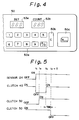
- Fig. 4 shows the main portion of the operation panel 50.
- the operation panel 50 includes a ten key switch 50a for setting the copy number etc., a clear key 50b for clearing the set copy number etc., a print switch 50c for starting the copy operation, a set display portion 53a for displaying the set copy number etc., a count display portion 53b for displaying the currently copied number etc. and so on.
- the CPU 47 in Fig. 3 controls the display driver 52 to drive the set display portion 53a in Fig. 4, so as to display the copy number set by means of the ten key switch 50a.
- the CPU 47 controls the mechanism shown in Figs. 1 and 2 to perform the copy operation, counts the currently copied number and controls the display driver 52 to drive the count display portion 53b in Fig. 4, so as to display the currently copied number.
- the CPU 47 controls the display driver 52 to drive the count display portion 53b in Fig. 4, so as to display "0".
- Fig. 5 shows the timing chart of the operation by the CPU 47 to control the transporting rollers 22 and the resist rollers 23 via the motors 35 and 43, and the clutches 30, 32 and 40.
- Figs. 6A to 6C show the various conditions of the recording sheet 18 in the sheet resist apparatus 1.
- the loop is formed of the recording sheet 18 at its tip portion, in the sheet resist apparatus 1, in which the CPU 47 in Fig. 3 controls in the manner shown in the timing chart of Fig. 4.
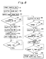
- Fig. 7 at the step S1, the print switch 50c is pushed ON, and the copy number is set via the ten key switch 50a. Then, CPU 47 starts the electrostatic processing device shown in Fig. 1, and make the clutch 40 and the braking clutch 30 in the ON condition, at the step S2.
- the recording sheet 18 positioned at the top of the pile on the sheet supplying tray 17, is picked up by the sheet supplying belt 19, guided by the sheet guides 20 and 21 to the transporting rollers 22, pinched between the transporting rollers 22 and transported toward the resist rollers 23, at the step S3.
- the sheet sensor 24 detects the tip of the recording sheet 18 at the time t1 in Fig. 5, the sheet sensor 24 is turned ON at the step S4, and the flow branches to the step S5. Then, the clutch 40 is made in the OFF condition at the step S5, and the transporting rollers 22 is stopped before the tip of the recording sheet 18 reaches the nip portion of the resist rollers 23 as shown in Fig. 6A.
- This stopping control is executed by the braking device 38 shown in Fig. 2, wherein the control friction force of the braking device 38 with respect to the transporting rollers 22 is set smaller than the driving force of the motor 43 with respect to the transporting rollers 22.
- the braking clutch 30 is in the ON condition in order to prepare starting the rotation of the resist rollers 23, and the driving clutch 32 is made in the ON condition at the step S6. That is to say, the resist rollers 23 is not started yet to rotate by virtue of the braking clutch 30 at the time t2.
- step S7 if it comes the time t3, which is before the transfer timing T by the timing tms, the flow branches to the step S8.
- the CPU 47 outputs the control signal to the clutch 40 so as to make the clutch 40 in the ON condition.
- the inclination of the recording sheet 18 is eliminated as the loop is formed by abutting the nip portion of the rollers at the tip of the recording sheet 18, as shown in Fig. 6B.
- the braking clutch 30 is made in the OFF condition as shown in Fig. 5.
- the recording sheet 18 is started to be transported to the transfer position by the resist rollers 23 and the transporting rollers 22 as shown in Fig. 6C.
- the operation is continued as following. Namely, at first, at the step S11, it is checked if the tale of the recording sheet 18 has passed through the sheet sensor 24 or not, according to the condition of the sheet sensor 24, and this checking process is repeated until the sheet sensor 24 is turned OFF, i.e. until the tale of the recording sheet 18 passes through the sheet sensor 24.
- the sheet sensor 24 is turned OFF, the flow branches to the step S12.
- the time necessary for the recording sheet 18 to further pass through the resist rollers 23 after passing though the sheet sensor 24, is set to the timer as the time period T1. Then, the CPU 47 checks the count-out of the timer i.e. the time out of the time period T1 at the step S13. If it is judged that the time period T1 has expired at the step S13, the flow branches to the step S14. At the step S14, it is assumed that the tale of the recording sheet 18 has passed through the resist rollers 23, and thus the CPU 47 stops the transporting rollers 22 and the resist rollers 23 so as to stop the transportation of the recording sheet 18, and at the same time, the reset and stop the timer.
- the step S7 in Fig. 7 may be replaced by the sub-steps 7a to 7c shown in the flowchart of Fig. 8, which shows another operation of the sheet resist apparatus 1 of Fig. 1.
- the flowchart of Fig. 8 is different from that of Fig. 7 only as for the step S7, otherwise the steps are same. Therefore, the same reference numerals are attached to these same steps, and the explanations thereof are omitted.
- the timing (predetermined time period) tms is to be changed according to the characteristic of the recording sheet
- the characteristic of the recording sheet is automatically detected, and the recording sheet data set by the operator in advance, is read out from the RAM 49 at the step S7a.
- the appropriate timing tms is set on the basis of the record sheet data read out from the RAM 49 at the step S7b. Then, it is checked if it is before the timing T by the set timing tms or not. If it is before the timing T by the set timing tms, the flow branches to the step, S7c. At the step S7c, the control signal is outputted from the CPU 47, to make the clutch 30 OFF.
- the predetermined time period tms may be stored into the RAM 49 as a standard time period t, which corresponds to an average sheet, after an adjustment for each image forming apparatus at its shipment, since the appropriate time period tms depends on the material of the rotating members such as the transporting rollers 22, and the type and characteristic of the recording sheet 18.
- a plurality of the standard time periods peculiar to each type of the recording sheet may be stored in the RAM 48 in advance, and one of them can be selected by directing the type of the sheet by the operator through the operation panel 50 just before the relevant copy operation.
- the predetermined time period tms may be set by automatically judging the characteristic of the sheet with referring to the photo-permeability of the recording sheet 18, the electric resistance of the recording sheet 18, or the electrostatic capacity of the recording sheet 18.
- the predetermined time period tms may be changed in the CPU 47 by an external input command, through the operation panel, for example.
- the CPU 47 controls the motors 35 and 43 on the basis of the result of detection of the sheet sensor 24.
- the motor 43 stops driving the transporting rollers 23 once before the tip of the recording sheet 18 reaches the resist rollers 23, and the motor 43 resumes driving the transporting rollers 22 earlier than the motor 35 starts driving the resist rollers 23 by the predetermined time period.
- the loop of the recording sheet 18 is formed at the tip portion thereof after this tip of the recording sheet 18 reaches the nip portion of the resist rollers 23.
- the possible inclination of the transported recording sheet 18 is eliminated by this formed loop, and then, when the predetermined time period has passed, the resist rollers 23 start rotating to further transport the recording sheet 18 to the photosensitive dram 10.
- the loop can be made before the resist rollers 23 start rotating and, at the same time, the waiting time for the recording sheet 18, which is formed in a loop, can be made quite short, with a result that a quite reliable elimination of the inclination and a precise and certain positioning of the tip of the recording sheet 18 are realized.
- the recording sheet 18, which is not curled and is free from inclination, can be speedily transported, through the sheet resist apparatus 1, to improve the quality of the formed image of the image forming apparatus.
Landscapes
- Registering Or Overturning Sheets (AREA)
- Delivering By Means Of Belts And Rollers (AREA)
- Paper Feeding For Electrophotography (AREA)
- Handling Of Cut Paper (AREA)
- Control Or Security For Electrophotography (AREA)
- Controlling Sheets Or Webs (AREA)
Applications Claiming Priority (2)
| Application Number | Priority Date | Filing Date | Title |
|---|---|---|---|
| JP2254705A JP2760648B2 (ja) | 1990-09-25 | 1990-09-25 | シートレジスト装置 |
| JP254705/90 | 1990-09-25 |
Publications (3)
| Publication Number | Publication Date |
|---|---|
| EP0477780A2 true EP0477780A2 (de) | 1992-04-01 |
| EP0477780A3 EP0477780A3 (en) | 1992-12-16 |
| EP0477780B1 EP0477780B1 (de) | 1995-06-28 |
Family
ID=17268707
Family Applications (1)
| Application Number | Title | Priority Date | Filing Date |
|---|---|---|---|
| EP91115951A Expired - Lifetime EP0477780B1 (de) | 1990-09-25 | 1991-09-19 | Blattrückhaltevorrichtung |
Country Status (4)
| Country | Link |
|---|---|
| US (1) | US5136342A (de) |
| EP (1) | EP0477780B1 (de) |
| JP (1) | JP2760648B2 (de) |
| DE (1) | DE69110813T2 (de) |
Cited By (5)
| Publication number | Priority date | Publication date | Assignee | Title |
|---|---|---|---|---|
| EP0622221A2 (de) * | 1993-04-30 | 1994-11-02 | Hewlett-Packard Company | Blattzuführung für einen durch Computer gesteuerten Drucker |
| EP0704771A1 (de) * | 1994-09-30 | 1996-04-03 | Mita Industrial Co., Ltd. | Vorrichtung zum Transport von blattförmigen Materialen |
| DE4309445B4 (de) * | 1992-03-24 | 2005-01-27 | Pentax Corp. | Elektrofotografisches Gerät |
| DE19621118B4 (de) * | 1995-05-24 | 2005-09-08 | Seiko Epson Corp. | Druckbeginnverfahren für Drucker und Drucker |
| CN106183467A (zh) * | 2014-11-07 | 2016-12-07 | 富士施乐株式会社 | 传送装置和传送系统 |
Families Citing this family (11)
| Publication number | Priority date | Publication date | Assignee | Title |
|---|---|---|---|---|
| JP3610076B2 (ja) * | 1991-12-10 | 2005-01-12 | キヤノン株式会社 | 記録装置 |
| JPH05338854A (ja) * | 1992-06-03 | 1993-12-21 | Fuji Xerox Co Ltd | 転写材搬送制御装置 |
| US5278624A (en) * | 1992-07-07 | 1994-01-11 | Xerox Corporation | Differential drive for sheet registration drive rolls with skew detection |
| JPH06102727A (ja) * | 1992-09-21 | 1994-04-15 | Konica Corp | 複写機 |
| US5418604A (en) * | 1992-09-28 | 1995-05-23 | Fujitsu Limited | Image forming method and apparatus with automatic skew control |
| JPH07261573A (ja) * | 1994-03-24 | 1995-10-13 | Canon Inc | 画像形成装置 |
| US5809391A (en) * | 1995-09-19 | 1998-09-15 | Fuji Xerox Co., Ltd. | Image forming apparatus enabling easy and reliable recovery from a pop jam |
| JP3395027B2 (ja) * | 1995-10-02 | 2003-04-07 | コニカ株式会社 | 画像形成装置 |
| US6289183B1 (en) * | 1998-12-21 | 2001-09-11 | Canon Kabushiki Kaisha | Sheet conveying apparatus and image forming apparatus having the same |
| US7280798B2 (en) * | 2004-03-09 | 2007-10-09 | Canon Kabushiki Kaisha | Image forming apparatus with conveying device urging a recording material toward a charge eliminating member |
| JP5610149B2 (ja) | 2010-11-01 | 2014-10-22 | 株式会社リコー | シート給送装置及び画像形成装置 |
Citations (4)
| Publication number | Priority date | Publication date | Assignee | Title |
|---|---|---|---|---|
| JPS59172344A (ja) * | 1983-03-22 | 1984-09-29 | Konishiroku Photo Ind Co Ltd | 用紙給送方法 |
| EP0228789A2 (de) * | 1985-11-09 | 1987-07-15 | Fujitsu Limited | Verfahren und Vorrichtung für das Ausrichten von Einzelblättern |
| JPS62259944A (ja) * | 1986-04-30 | 1987-11-12 | Nec Corp | 用紙斜行補正機構 |
| US4884909A (en) * | 1986-12-25 | 1989-12-05 | Canon Kabushiki Kaisha | Recording apparatus |
Family Cites Families (7)
| Publication number | Priority date | Publication date | Assignee | Title |
|---|---|---|---|---|
| US3963339A (en) * | 1974-09-05 | 1976-06-15 | Xerox Corporation | Sheet feeding apparatus |
| JPS60173560A (ja) * | 1984-02-18 | 1985-09-06 | Mita Ind Co Ltd | 複写機における給紙搬送方法及びその装置 |
| US4669853A (en) * | 1985-11-06 | 1987-06-02 | Xerox Corporation | Automatic buckle adjust |
| JPS64555U (de) * | 1987-06-23 | 1989-01-05 | ||
| US4956651A (en) * | 1987-07-01 | 1990-09-11 | Minolta Camera Kabushiki Kaisha | Image forming apparatus which sheet detection and timing control |
| US5043771A (en) * | 1988-05-24 | 1991-08-27 | Konica Corporation | Image forming apparatus having a controller for controlling the registration rollers |
| JPH03249047A (ja) * | 1990-02-22 | 1991-11-07 | Canon Inc | 画像形成装置 |
-
1990
- 1990-09-25 JP JP2254705A patent/JP2760648B2/ja not_active Expired - Lifetime
-
1991
- 1991-09-18 US US07/761,652 patent/US5136342A/en not_active Expired - Lifetime
- 1991-09-19 EP EP91115951A patent/EP0477780B1/de not_active Expired - Lifetime
- 1991-09-19 DE DE69110813T patent/DE69110813T2/de not_active Expired - Lifetime
Patent Citations (4)
| Publication number | Priority date | Publication date | Assignee | Title |
|---|---|---|---|---|
| JPS59172344A (ja) * | 1983-03-22 | 1984-09-29 | Konishiroku Photo Ind Co Ltd | 用紙給送方法 |
| EP0228789A2 (de) * | 1985-11-09 | 1987-07-15 | Fujitsu Limited | Verfahren und Vorrichtung für das Ausrichten von Einzelblättern |
| JPS62259944A (ja) * | 1986-04-30 | 1987-11-12 | Nec Corp | 用紙斜行補正機構 |
| US4884909A (en) * | 1986-12-25 | 1989-12-05 | Canon Kabushiki Kaisha | Recording apparatus |
Non-Patent Citations (2)
| Title |
|---|
| PATENT ABSTRACTS OF JAPAN vol. 12, no. 141 (M-691)(2988), 28 April 1988; & JP - A - 62259944 (NEC) 12.11.1987 * |
| PATENT ABSTRACTS OF JAPAN vol. 9, no. 29 (M-356)(1752), 7 February 1985; & JP - A - 59172344 (KONISHIROKU) 29.09.1984 * |
Cited By (8)
| Publication number | Priority date | Publication date | Assignee | Title |
|---|---|---|---|---|
| DE4309445B4 (de) * | 1992-03-24 | 2005-01-27 | Pentax Corp. | Elektrofotografisches Gerät |
| EP0622221A2 (de) * | 1993-04-30 | 1994-11-02 | Hewlett-Packard Company | Blattzuführung für einen durch Computer gesteuerten Drucker |
| EP0622221A3 (de) * | 1993-04-30 | 1995-11-08 | Hewlett Packard Co | Blattzuführung für einen durch Computer gesteuerten Drucker. |
| EP0704771A1 (de) * | 1994-09-30 | 1996-04-03 | Mita Industrial Co., Ltd. | Vorrichtung zum Transport von blattförmigen Materialen |
| US5738349A (en) * | 1994-09-30 | 1998-04-14 | Mita Industrial Co., Ltd. | Device for conveying sheet members |
| DE19621118B4 (de) * | 1995-05-24 | 2005-09-08 | Seiko Epson Corp. | Druckbeginnverfahren für Drucker und Drucker |
| CN106183467A (zh) * | 2014-11-07 | 2016-12-07 | 富士施乐株式会社 | 传送装置和传送系统 |
| CN106183467B (zh) * | 2014-11-07 | 2019-04-05 | 富士施乐株式会社 | 传送装置和传送系统 |
Also Published As
| Publication number | Publication date |
|---|---|
| JPH04133070A (ja) | 1992-05-07 |
| DE69110813D1 (de) | 1995-08-03 |
| US5136342A (en) | 1992-08-04 |
| DE69110813T2 (de) | 1996-02-22 |
| JP2760648B2 (ja) | 1998-06-04 |
| EP0477780A3 (en) | 1992-12-16 |
| EP0477780B1 (de) | 1995-06-28 |
Similar Documents
| Publication | Publication Date | Title |
|---|---|---|
| EP0477780B1 (de) | Blattrückhaltevorrichtung | |
| US5678127A (en) | Sheet supply apparatus with control based on detected sheet length | |
| US6786483B2 (en) | Sheet processing apparatus and image forming system having the same | |
| US6065383A (en) | Punching system | |
| EP0402836A2 (de) | Bilderzeugunsgerät | |
| JP3610076B2 (ja) | 記録装置 | |
| US6606928B2 (en) | Punching system | |
| JPH09175694A (ja) | シート搬送装置 | |
| CA1326259C (en) | Large document copying system | |
| US5222728A (en) | Sheet transporting device having variable loop sheet alignment | |
| US5765093A (en) | Image recording apparatus with recording medium bending | |
| US4839697A (en) | Image forming apparatus | |
| JPH085966Y2 (ja) | 用紙搬送装置 | |
| JPH10101238A (ja) | シート供給装置 | |
| JP2964703B2 (ja) | 画像形成装置の用紙送り装置 | |
| JPH04235848A (ja) | シート材搬送装置 | |
| JP2974054B2 (ja) | 用紙搬送装置 | |
| JPH11165906A (ja) | 用紙搬送装置 | |
| JP2830135B2 (ja) | 記録媒体の繰り出し装置 | |
| JPH05208756A (ja) | 用紙給送装置 | |
| JPH11343050A (ja) | シート給送装置及び画像処理装置 | |
| JPH075075Y2 (ja) | 手差し給紙装置 | |
| JP2554476Y2 (ja) | 複写機における複写紙整合装置 | |
| JP2855761B2 (ja) | 画像形成装置の中間給紙装置 | |
| JPH0540378A (ja) | 画像形成装置 |
Legal Events
| Date | Code | Title | Description |
|---|---|---|---|
| PUAI | Public reference made under article 153(3) epc to a published international application that has entered the european phase |
Free format text: ORIGINAL CODE: 0009012 |
|
| AK | Designated contracting states |
Kind code of ref document: A2 Designated state(s): DE FR GB |
|
| PUAL | Search report despatched |
Free format text: ORIGINAL CODE: 0009013 |
|
| AK | Designated contracting states |
Kind code of ref document: A3 Designated state(s): DE FR GB |
|
| 17P | Request for examination filed |
Effective date: 19930310 |
|
| 17Q | First examination report despatched |
Effective date: 19940823 |
|
| GRAA | (expected) grant |
Free format text: ORIGINAL CODE: 0009210 |
|
| AK | Designated contracting states |
Kind code of ref document: B1 Designated state(s): DE FR GB |
|
| REF | Corresponds to: |
Ref document number: 69110813 Country of ref document: DE Date of ref document: 19950803 |
|
| ET | Fr: translation filed | ||
| PLBE | No opposition filed within time limit |
Free format text: ORIGINAL CODE: 0009261 |
|
| STAA | Information on the status of an ep patent application or granted ep patent |
Free format text: STATUS: NO OPPOSITION FILED WITHIN TIME LIMIT |
|
| 26N | No opposition filed | ||
| REG | Reference to a national code |
Ref country code: GB Ref legal event code: IF02 |
|
| PGFP | Annual fee paid to national office [announced via postgrant information from national office to epo] |
Ref country code: FR Payment date: 20100921 Year of fee payment: 20 |
|
| PGFP | Annual fee paid to national office [announced via postgrant information from national office to epo] |
Ref country code: GB Payment date: 20100916 Year of fee payment: 20 |
|
| PGFP | Annual fee paid to national office [announced via postgrant information from national office to epo] |
Ref country code: DE Payment date: 20100915 Year of fee payment: 20 |
|
| REG | Reference to a national code |
Ref country code: DE Ref legal event code: R071 Ref document number: 69110813 Country of ref document: DE |
|
| REG | Reference to a national code |
Ref country code: DE Ref legal event code: R071 Ref document number: 69110813 Country of ref document: DE |
|
| REG | Reference to a national code |
Ref country code: GB Ref legal event code: PE20 Expiry date: 20110918 |
|
| PG25 | Lapsed in a contracting state [announced via postgrant information from national office to epo] |
Ref country code: GB Free format text: LAPSE BECAUSE OF EXPIRATION OF PROTECTION Effective date: 20110918 |
|
| PG25 | Lapsed in a contracting state [announced via postgrant information from national office to epo] |
Ref country code: DE Free format text: LAPSE BECAUSE OF EXPIRATION OF PROTECTION Effective date: 20110920 |