EP0477313B1 - Badelift - Google Patents
Badelift Download PDFInfo
- Publication number
- EP0477313B1 EP0477313B1 EP91906254A EP91906254A EP0477313B1 EP 0477313 B1 EP0477313 B1 EP 0477313B1 EP 91906254 A EP91906254 A EP 91906254A EP 91906254 A EP91906254 A EP 91906254A EP 0477313 B1 EP0477313 B1 EP 0477313B1
- Authority
- EP
- European Patent Office
- Prior art keywords
- upper frame
- bath lift
- platform
- bath
- lower frame
- Prior art date
- Legal status (The legal status is an assumption and is not a legal conclusion. Google has not performed a legal analysis and makes no representation as to the accuracy of the status listed.)
- Expired - Lifetime
Links
Images
Classifications
-
- A—HUMAN NECESSITIES
- A61—MEDICAL OR VETERINARY SCIENCE; HYGIENE
- A61G—TRANSPORT, PERSONAL CONVEYANCES, OR ACCOMMODATION SPECIALLY ADAPTED FOR PATIENTS OR DISABLED PERSONS; OPERATING TABLES OR CHAIRS; CHAIRS FOR DENTISTRY; FUNERAL DEVICES
- A61G7/00—Beds specially adapted for nursing; Devices for lifting patients or disabled persons
- A61G7/10—Devices for lifting patients or disabled persons, e.g. special adaptations of hoists thereto
- A61G7/1001—Devices for lifting patients or disabled persons, e.g. special adaptations of hoists thereto specially adapted for specific applications
- A61G7/1003—Devices for lifting patients or disabled persons, e.g. special adaptations of hoists thereto specially adapted for specific applications mounted on or in combination with a bath-tub
-
- A—HUMAN NECESSITIES
- A61—MEDICAL OR VETERINARY SCIENCE; HYGIENE
- A61G—TRANSPORT, PERSONAL CONVEYANCES, OR ACCOMMODATION SPECIALLY ADAPTED FOR PATIENTS OR DISABLED PERSONS; OPERATING TABLES OR CHAIRS; CHAIRS FOR DENTISTRY; FUNERAL DEVICES
- A61G7/00—Beds specially adapted for nursing; Devices for lifting patients or disabled persons
- A61G7/10—Devices for lifting patients or disabled persons, e.g. special adaptations of hoists thereto
- A61G7/1013—Lifting of patients by
- A61G7/1019—Vertical extending columns or mechanisms
-
- A—HUMAN NECESSITIES
- A61—MEDICAL OR VETERINARY SCIENCE; HYGIENE
- A61G—TRANSPORT, PERSONAL CONVEYANCES, OR ACCOMMODATION SPECIALLY ADAPTED FOR PATIENTS OR DISABLED PERSONS; OPERATING TABLES OR CHAIRS; CHAIRS FOR DENTISTRY; FUNERAL DEVICES
- A61G7/00—Beds specially adapted for nursing; Devices for lifting patients or disabled persons
- A61G7/10—Devices for lifting patients or disabled persons, e.g. special adaptations of hoists thereto
- A61G7/1049—Attachment, suspending or supporting means for patients
- A61G7/1057—Supported platforms, frames or sheets for patient in lying position
-
- B—PERFORMING OPERATIONS; TRANSPORTING
- B66—HOISTING; LIFTING; HAULING
- B66F—HOISTING, LIFTING, HAULING OR PUSHING, NOT OTHERWISE PROVIDED FOR, e.g. DEVICES WHICH APPLY A LIFTING OR PUSHING FORCE DIRECTLY TO THE SURFACE OF A LOAD
- B66F7/00—Lifting frames, e.g. for lifting vehicles; Platform lifts
- B66F7/06—Lifting frames, e.g. for lifting vehicles; Platform lifts with platforms supported by levers for vertical movement
- B66F7/065—Scissor linkages, i.e. X-configuration
-
- A—HUMAN NECESSITIES
- A61—MEDICAL OR VETERINARY SCIENCE; HYGIENE
- A61G—TRANSPORT, PERSONAL CONVEYANCES, OR ACCOMMODATION SPECIALLY ADAPTED FOR PATIENTS OR DISABLED PERSONS; OPERATING TABLES OR CHAIRS; CHAIRS FOR DENTISTRY; FUNERAL DEVICES
- A61G2200/00—Information related to the kind of patient or his position
- A61G2200/30—Specific positions of the patient
- A61G2200/32—Specific positions of the patient lying
-
- A—HUMAN NECESSITIES
- A61—MEDICAL OR VETERINARY SCIENCE; HYGIENE
- A61G—TRANSPORT, PERSONAL CONVEYANCES, OR ACCOMMODATION SPECIALLY ADAPTED FOR PATIENTS OR DISABLED PERSONS; OPERATING TABLES OR CHAIRS; CHAIRS FOR DENTISTRY; FUNERAL DEVICES
- A61G2200/00—Information related to the kind of patient or his position
- A61G2200/30—Specific positions of the patient
- A61G2200/34—Specific positions of the patient sitting
Definitions
- the invention relates to a bath lift for disabled people. Such bath lifts are known and are used both in hospitals and for home care.
- the present invention relates in particular to a portable bath lift for home care.
- the invention is based on the known construction of a lifting table, the plate of which can be raised and lowered with the aid of scissors construction.
- This construction has the disadvantage that lifting the plate from the lowest position requires a very large force.
- a bath lift must be able to be lowered as far as possible.
- the invention is therefore based on a known bath lift according to the preamble of claim 1 based on DE-A-3743 193.
- the invention has set itself the task of creating a purely mechanical bath lift that has none of the disadvantages mentioned.
- the invention is solved by the features mentioned in the characterizing part.
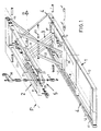
- the main components of the bath lift are a lower frame 1, an upper frame 2 with a seat plate P indicated by dash-dotted lines, a scissor structure 3, two torsion spring bars 4 and a drive mechanism 5.
- Both frames 1, 2 are composed of profiles, the lower frame 1 being longer than the upper frame 2.
- the scissor structure 3 is pivotally attached to the rear end region of both frames.
- the scissor legs 31 pivotally attached to the lower frame are narrower than the scissor legs 32 pivotally attached to the upper frame.
- the scissor legs themselves are designed as a frame construction and are pivotally connected to one another in the middle about an axis 33.
- both scissor legs are provided with rollers 35 which run in U-profile pieces 21, 11 and allow the leg ends to be displaced parallel to the longitudinal spars 12, 23 of the frames 1, 2 during height adjustment.
- Torsion spring bars 4 are accommodated in both longitudinal spars 12 of the lower frame 1. At one end they are firmly connected to the frame, here by an angled end 41 which is held in the frame 1. At the other end, the spring bars lead out of the spars 12 and are angled. These angled ends form the lever arm of the torsion bar. With the help of this lever arm, the torsion bar can be twisted about its longitudinal axis, with the aim of returning to its starting position.
- a tube 42 with a tight fit is pushed onto the lever arm of the torsion bar itself, so that the lever arm does not bend itself during loading.
- a second tube 43 is slid over this tube 42 and can be telescopically displaced on the first tube 42.
- These second tubes 43 are articulated at 44 to the rear end of the upper frame 2.
- the torsion spring bars arranged in this way have the favorable property for the bath lift that their spring force, which tends to push the upper frame 2 upwards, is greatest in the lowest operating position.
- the actuating mechanism 5 essentially consists of a screw spindle 51 (see FIG. 2) which is rotatably mounted at one end but axially fixed in a crossbeam 22 between the longitudinal spars of the upper frame 2 and a block 52 which is connected to the upper end of the scissor legs 31 is.
- Block 52 has an internal thread corresponding to the thread of the spindle.
- the spindle 51 is driven by means of a worm gear with worm 53 and worm wheel 54.
- the worm shaft is at the top with a protruding from the bearing Hexagon 55 provided, on which a crank 56 can be attached.
- the bath lift is constructed as light as possible, aluminum parts are used.
- the torsion spring bars are made of stainless steel. They are only slightly pretensioned in the highest position of the seat shown in the figures, but exert an upward force of approximately 80 kg in the lowest position of the seat. They therefore compensate for the weight of the user at least almost completely. It is therefore possible for the bathing person to raise the seat plate of the lift from the lowest position to the edge of the bathtub again without help by means of the crank 56.
Landscapes
- Health & Medical Sciences (AREA)
- Life Sciences & Earth Sciences (AREA)
- Nursing (AREA)
- Animal Behavior & Ethology (AREA)
- General Health & Medical Sciences (AREA)
- Public Health (AREA)
- Veterinary Medicine (AREA)
- Engineering & Computer Science (AREA)
- Geology (AREA)
- Mechanical Engineering (AREA)
- Structural Engineering (AREA)
- Devices For Medical Bathing And Washing (AREA)
Abstract
Description
- Die Erfindung bezieht sich auf einen Badelift für behinderte Personen. Solche Badelifte sind bekannt und werden sowohl in Spitälern als auch bei der Heimpflege gebraucht. Die vorliegende Erfindung bezieht sich insbesondere auf einen transportablen Badelift für die Heimpflege.
- Bei dieser Art Badelifte gibt es solche, die hydraulisch mit dem Wasserdruck aus der Leitung arbeiten und andere die rein mechanisch arbeiten. Die hydraulischen Badelifte, die mit Wasser aus der Leitung arbeiten, versagen oft in einem höheren Stockwerk, weil dann der Druck in der Leitung zu gering ist. Die mechanisch arbeitenden Badelifte bedingen oft die Hilfe einer zweiten Person. Bei einem mechanischen Badelift, der mit Hilfe von Federkraft arbeitet, ist zu beachten, dass sich die Senkbewegung des Benützers infolge der zunehmenden Federkraft verringert, so dass eine Hilfsperson den Badenden nach unten drücken muss, wo der Lift verankert werden kann.
- Die Erfindung geht dabei von der an sich bekannten Konstruktion eines Hebetisches aus, deren Platte mit Hilfe einer Scherenkonstruktion hebbar und senkbar ist. Diese Konstruktion hat den Nachteil, dass ein Anheben der Platte aus der untersten Lage eine sehr grosse Kraft erfordert. Ein Badelift muss aber so tief wie möglich absenkbar sein.
- Trotzdem sollte der Benützer selber, ohne fremde Hilfe, im Stande sein, die Sitzfläche seines Badeliftes mit eigener Kraft bis etwa zur Höhe des Wannenrandes anzuheben! Die Erfindung geht daher aus von einem bekannten Badelift gemäss dem auf die DE-A-3743 193 basierenden Oberbegriff des Patentanspruches 1.
- Die Erfindung hat sich zur Aufgabe gestellt, einen rein mechanisch arbeitenden Badelift zu schaffen, der keinen der genannten Nachteile aufweist.
- Die Erfindung wird durch die im kennzeichnenden Teil genannten Merkmale gelöst.
- In der beigefügten Zeichnung ist ein Ausführungsbeispiel des Erfindungsgegenstandes dargestellt. Es zeigen:
- Figur 1
- eine aufgegliederte perspektivische Darstellung eines Badeliftes und
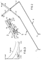
- Figur 2
- die Torsions-Federstäbe für sich mit einem Teil des Antriebes.
- Figur 3
- ein Diagramm.
- Die Hauptbestandteile des Badeliftes sind ein unterer Rahmen 1, ein oberer Rahmen 2 mit einer durch Strich-Punktlinien angedeutete Sitzplatte P, eine Scherenkonstruktion 3, zwei Torsion-Federstäbe 4 und ein Antriebsmechanismus 5.
- Beide Rahmen 1, 2 sind aus Profilen zusammengesetzt, wobei der untere Rahmen 1 länger ist als der obere Rahmen 2. Am rückseitigen Endbereich beider Rahmen ist die Scherenkonstruktion 3 schwenkbar befestigt. Die am unteren Rahmen schwenkbar befestigten Scherenschenkel 31 sind schmäler ausgebildet als die am oberen Rahmen schwenkbar befestigten Scherenschenkel 32. Die Scherenschenkel selber sind als Rahmenkonstruktion ausgebildet und in der Mitte schwenkbar um eine Achse 33 miteinander verbunden. Am verschiebbaren Ende sind beide Scherenschenkel mit Rollen 35 versehen, die in U-Profilstücken 21,11 laufen und eine Verschiebung der Schenkelenden parallel zu den Längsholmen 12,23 der Rahmen 1,2 während einer Höhenverstellung ermöglichen.
- In beiden Längsholmen 12 des unteren Rahmens 1 sind Torsions-Federstäbe 4 untergebracht. An einem Ende sind sie fest mit dem Rahmen verbunden, hier durch ein abgewinkeltes Ende 41, welches im Rahmen 1 gehalten ist. Am anderen Ende führen die Federstäbe aus den Holmen 12 heraus und sind abgewinkelt. Diese abgewinkelten Enden bilden den Hebelarm des Torsionsstabes. Mit Hilfe dieses Hebelarmes kann der Torsionsstab um seine Längsachse tordiert werden, wobei er das Bestreben hat, in seine Ausgangslage zurückzukehren.
- Auf den Hebelarm des Torsionstabes selber ist ein Rohr 42 mit festem Sitz geschoben, damit sich der Hebelarm selber während der Belastung nicht verbiegt. Ueber dieses Rohr 42 ist ein zweites Rohr 43 geschoben, welches sich teleskopisch auf dem erstgenannten Rohr 42 verschieben lässt.
- Diese zweiten Rohre 43 sind bei 44 gelenkig mit dem rückseitigen Ende des oberen Rahmens 2 verbunden.
- Damit die aus den Teilen 42,43 gebildeten Hebelarme sich kreuzend montiert werden können, wie in der Zeichnung dargestellt ist, ragt der in der Figur linke Hebelarm ein wenig weiter aus dem linken Holm 12 heraus als der rechte Hebelarm aus dem rechten Holm 12. Die Hebelarme 42,43 müssen teleskopisch ausgebildet sein, weil sich deren Länge beim Senken verkürzt und beim Anheben verlängert.
- Die derart angeordneten Torsions-Federstäbe haben die für den Badelift günstige Eigenschaft, dass ihre Federkraft, die das Bestreben hat, den oberen Rahmen 2 nach oben zu drücken in der untersten Betriebslage am grössten ist.
- Ein Anheben mit Hilfe des noch zu beschreibenden Betätigungsmechanismus wäre ohne die Hilfe der Torsions-Federstäbe kaum möglich. Es sei noch darauf hingewiesen, dass es von Vorteil ist, die Torsions-Federstäbe so anzuordnen, dass deren Hebelarme an derjenigen Seite liegen und auch dort Kraft ausüben, wo die Scherenkonstruktion gelenkig mit den beiden Rahmen 1,2 verbunden ist. Würden die Kräfte der Torsions-Federstäbe an der anderen Seite angreifen, wo die Schenkel 31,32 der Scherenkonstruktion gleitend gelagert sind, würde ein Verklemmen eintreten.
- Der Betätigungsmechanismus 5 besteht im wesentlichen aus einer Schraubspindel 51 (siehe Figur 2), die einenends drehbar, aber axial fest in einem Querbalken 22 zwischen den Längsholmen des oberen Rahmens 2 gelagert ist und einem Block 52, der mit dem oberen Ende der Scherenschenkels 31 verbunden ist. Block 52 ist mit einem Innengewinde entsprechend dem Gewinde der Spindel versehen. Die Spindel 51 wird mittels eines Schneckengetriebes mit Schnecke 53 und Schneckenrad 54 angetrieben. Die Schnekkenwelle ist oben mit einem aus dem Lager herausragenden Sechskant 55 versehen, auf welches eine Kurbel 56 aufgesteckt werden kann.
- Der Badelift ist so leicht wie möglich konstruiert, es sind Aluminiumteile verwendet. Die Torsion-Federstäbe bestehen aus rostfreiem Stahl. Sie sind in der, in den Figuren dargestellten, höchsten Lage der Sitzfläche nur leicht vorgespannt, üben aber in der tiefsten Lage der Sitzfläche eine nach oben gerichtete Kraft von etwa 80 Kilogramm aus. Sie kompensieren daher das Gewicht des Benützers mindestens annähernd vollständig. Es ist daher dem Badenden möglich, die Sitzplatte des Liftes ohne fremde Hilfe mittels der Kurbel 56 von der tiefsten Lage wieder bis zum Rand der Badewanne anzuheben.
- Die Federkraft und damit die Hebewirkung der Torsionsfedern nimmt immer mehr ab, je mehr die Sitzplatte angehoben wird. Beim Anheben der Sitzplatte bis zum Rand der Badewanne muss daher immer mehr Kraft an der Kurbel ausgeübt werden. Eine erhebliche Verbesserung lässt sich erreichen, wenn man im unteren Rahmen 1 zwischen den Verbindungsstreben 36,37, welche die unteren Enden der Scherenschenkel 31,32 miteinander verbinden, zwei Zugfedern 35,45 anbringt. Zwar nimmt deren Zugkraft gegen das Ende der Hubbewegung ebenfalls ab, es verbleibt aber doch eine restliche Zugkraft, die gegen das Ende der Hubbewegung sehr nützlich ist. Diese Verhältnisse sind im Diagramm der Figur 3 dargestellt.
- Am Ende des Hubes nimmt, die von den Torsionsfedern erzeugte Kraft fast bis auf Null ab, es bleibt aber eine Restkraft der Zugfedern. Diese ist zwar relativ klein, wobei aber zu bedenken ist, dass die benötigte Kraft zum Heben gemäss dem Hebelgesetz jetzt immer kleiner wird.
Claims (6)
- Badelift mit einem unteren Rahmen (1) mit Längsholmen (2) und einem oberen Rahmen (2) mit einer Sitzplatte (P), wobei die beiden Rahmen (1,2) durch eine Scherenkonstruktion (3) miteinander verbunden sind, dadurch gekennzeichnet, dass eine im oberen Rahmen (2) gelagerte Schraubspindel (51) der Höhenverstellung dient, daß im unteren Rahmen (1) zwei Torsions-Federstäbe (4) angeordnet sind, deren Hebelarme jeweils mit dem oberen Rahmen (2) in Wirkverbindung stehen, wobei in jedem der beiden Längsholme (12) des unteren Rahmens (1) ein Torsions-Federstab (4) angebracht ist, und dass deren Hebelarme sich kreuzen (42,43).
- Badelift nach Anspruch 1, dadurch gekennzeichnet, dass die Hebelarme der Torsionsfederstäbe (4) in darüber gestülpten, teleskopisch verschiebbaren Rohren lagern, die mit dem oberen Rahmen (2) gelenkig (44) verbunden sind.
- Badelift nach den Ansprüchen 1 und 2, dadurch gekennzeichnet, dass die Torsions-Federstäbe so angebracht sind, dass deren sich kreuzenden Hebelarme (42,43) sich an demjenigen Ende der Rahmen (1,2) befinden, an denen die Schenkel (31,32) der Scherenkonstruktion (3) gelenkig mit den Rahmen (1,2) verbunden sind.
- Badelift nach Anspruch 1, dadurch gekennzeichnet, dass im oberen Rahmen (2,21) verschiebbar gelagerten Enden der Scherenschenkel (31) schwenkbar mit einem Block (52) verbunden sind, der ein Innengewinde aufweist, in welches eine Schraubspindel (51) eingreift, deren Ende in einem Querbalken (22) des oberen Rahmens drehbar, aber axial fest gelagert ist.
- Badelift nach Anspruch 4, dadurch gekennzeichnet, dass das Ende der Schraubspindel mit einem Schneckengetriebe (53,54) versehen ist, dessen Schnecke (53) mit Hilfe einer wegnehmbaren Kurbel (56) antreibbar ist.
- Badelift nach Anspruch 1, dadurch gekennzeichnet, dass im unteren Rahmen (1) zwischen den Verbindungsstreben (36,37), welche die unteren Enden der Scherenschenkel (31,32) miteinander verbinden, mindestens eine Zugfeder angeordnet ist.
Priority Applications (1)
| Application Number | Priority Date | Filing Date | Title |
|---|---|---|---|
| AT9191906254T ATE105169T1 (de) | 1990-04-11 | 1991-03-27 | Badelift. |
Applications Claiming Priority (3)
| Application Number | Priority Date | Filing Date | Title |
|---|---|---|---|
| CH1247/90 | 1990-04-11 | ||
| CH124790 | 1990-04-11 | ||
| PCT/CH1991/000079 WO1991015179A1 (de) | 1990-04-11 | 1991-03-27 | Badelift |
Publications (2)
| Publication Number | Publication Date |
|---|---|
| EP0477313A1 EP0477313A1 (de) | 1992-04-01 |
| EP0477313B1 true EP0477313B1 (de) | 1994-05-04 |
Family
ID=4205925
Family Applications (1)
| Application Number | Title | Priority Date | Filing Date |
|---|---|---|---|
| EP91906254A Expired - Lifetime EP0477313B1 (de) | 1990-04-11 | 1991-03-27 | Badelift |
Country Status (3)
| Country | Link |
|---|---|
| EP (1) | EP0477313B1 (de) |
| DE (1) | DE59101566D1 (de) |
| WO (1) | WO1991015179A1 (de) |
Families Citing this family (3)
| Publication number | Priority date | Publication date | Assignee | Title |
|---|---|---|---|---|
| DE102005048642B4 (de) * | 2005-10-11 | 2010-03-04 | Dentler Reha-Technik Gmbh & Co. Kg | Badelifter für Behinderte und Gebrechliche, sowie kranke Personen mit einer Hebevorrichtung |
| DE102006037367A1 (de) * | 2006-08-09 | 2008-02-14 | Petermann Gmbh | Badewannenlifter |
| EP3453372B1 (de) * | 2017-09-08 | 2023-03-29 | Drive Medical GmbH & Co. KG | Hubscherensystem für badewannenlifter |
Family Cites Families (4)
| Publication number | Priority date | Publication date | Assignee | Title |
|---|---|---|---|---|
| DE7201691U (de) * | Molt O | |||
| DE3508056A1 (de) * | 1985-03-07 | 1986-09-18 | Peter 7989 Eisenharz Schmidt | Badewanneneinsatz |
| US4750712A (en) * | 1986-06-05 | 1988-06-14 | Jolanda Genovese | Vehicle lifting device |
| DE3743193A1 (de) * | 1987-12-19 | 1989-06-29 | Peter Schmidt | Badewanneneinsatz |
-
1991
- 1991-03-27 DE DE59101566T patent/DE59101566D1/de not_active Expired - Fee Related
- 1991-03-27 WO PCT/CH1991/000079 patent/WO1991015179A1/de not_active Ceased
- 1991-03-27 EP EP91906254A patent/EP0477313B1/de not_active Expired - Lifetime
Also Published As
| Publication number | Publication date |
|---|---|
| DE59101566D1 (de) | 1994-06-09 |
| WO1991015179A1 (de) | 1991-10-17 |
| EP0477313A1 (de) | 1992-04-01 |
Similar Documents
| Publication | Publication Date | Title |
|---|---|---|
| DE69114115T2 (de) | Vorrichtung zum Ausführen von Kopf- und Fuss-Trendelenburgtherapie. | |
| DE19543301A1 (de) | Hubvorrichtung für Sitz-, Liege- oder Abstellflächen | |
| DE2837668A1 (de) | Hebebuehne | |
| DE1580662B2 (de) | Unterhalb einer ladeflaeche, insbesondere eines fahrzeuges, verstaubare ladebuehne | |
| DE102021114748A1 (de) | Mechanismus zum Umwandeln eines Möbelstücks von einer Sitz- in eine Liegeposition | |
| EP0356761B1 (de) | Scherenhubvorrichtung, insbesondere für eine Arbeitsbühne | |
| EP0477313B1 (de) | Badelift | |
| DE2630601A1 (de) | Scherenspreizer-hebevorrichtung | |
| DE19604074B4 (de) | Hubvorrichtung für Pflegebetten | |
| CH522804A (de) | Einstellbare Stütze, insbesondere für Verschalungen | |
| DE20316058U1 (de) | Scherenhubvorrichtung für eine Liege oder einen Tisch | |
| DE4211352C2 (de) | Schwenkbeschlag für Möbel zur motorischen Verstellung von schwenkbaren Teilen | |
| EP1886656B1 (de) | Badewannenlifter | |
| DE2851555A1 (de) | Scherenhebetisch | |
| DE649176C (de) | Hubwagen | |
| DE19747868A1 (de) | Gebärwanne | |
| DE8606879U1 (de) | Krankenbett | |
| DE29719277U1 (de) | Gebärwanne | |
| CH276815A (de) | Elektrische Hebebühne. | |
| DE102005048642B4 (de) | Badelifter für Behinderte und Gebrechliche, sowie kranke Personen mit einer Hebevorrichtung | |
| EP0572351A1 (de) | Badelift | |
| DE3119524A1 (de) | Tragbares geraet zum anheben und absenken von lasten, insbesondere betten oder bettrosten | |
| DE24300C (de) | Neuerungen an Zucker* mühlen | |
| DE69918896T2 (de) | Hebebühne für Fahrzeuge mit Lenker zum Verringern von dem Anfangshubkraft | |
| DE723546C (de) | Kipprahmen fuer Lastkraftfahrzeuge mit X-foermiger Anordnung der Laengstraeger und mit mittlerem Quertraeger |
Legal Events
| Date | Code | Title | Description |
|---|---|---|---|
| PUAI | Public reference made under article 153(3) epc to a published international application that has entered the european phase |
Free format text: ORIGINAL CODE: 0009012 |
|
| 17P | Request for examination filed |
Effective date: 19911209 |
|
| AK | Designated contracting states |
Kind code of ref document: A1 Designated state(s): AT BE CH DE DK ES FR GB GR IT LI LU NL SE |
|
| 17Q | First examination report despatched |
Effective date: 19930726 |
|
| GRAA | (expected) grant |
Free format text: ORIGINAL CODE: 0009210 |
|
| AK | Designated contracting states |
Kind code of ref document: B1 Designated state(s): AT BE CH DE DK ES FR GB GR IT LI LU NL SE |
|
| PG25 | Lapsed in a contracting state [announced via postgrant information from national office to epo] |
Ref country code: IT Free format text: LAPSE BECAUSE OF FAILURE TO SUBMIT A TRANSLATION OF THE DESCRIPTION OR TO PAY THE FEE WITHIN THE PRE;WARNING: LAPSES OF ITALIAN PATENTS WITH EFFECTIVE DATE BEFORE 2007 MAY HAVE OCCURRED AT ANY TIME BEFORE 2007. THE CORRECT EFFECTIVE DATE MAY BE DIFFERENT FROM THE ONE RECORDED.SCRIBED TIME-LIMIT Effective date: 19940504 Ref country code: SE Free format text: THE PATENT HAS BEEN ANNULLED BY A DECISION OF A NATIONAL AUTHORITY Effective date: 19940504 Ref country code: FR Effective date: 19940504 Ref country code: ES Free format text: THE PATENT HAS BEEN ANNULLED BY A DECISION OF A NATIONAL AUTHORITY Effective date: 19940504 Ref country code: NL Effective date: 19940504 Ref country code: DK Effective date: 19940504 Ref country code: GB Effective date: 19940504 Ref country code: GR Free format text: LAPSE BECAUSE OF FAILURE TO SUBMIT A TRANSLATION OF THE DESCRIPTION OR TO PAY THE FEE WITHIN THE PRESCRIBED TIME-LIMIT Effective date: 19940504 Ref country code: BE Effective date: 19940504 |
|
| REF | Corresponds to: |
Ref document number: 105169 Country of ref document: AT Date of ref document: 19940515 Kind code of ref document: T |
|
| REF | Corresponds to: |
Ref document number: 59101566 Country of ref document: DE Date of ref document: 19940609 |
|
| EN | Fr: translation not filed | ||
| NLV1 | Nl: lapsed or annulled due to failure to fulfill the requirements of art. 29p and 29m of the patents act | ||
| GBV | Gb: ep patent (uk) treated as always having been void in accordance with gb section 77(7)/1977 [no translation filed] |
Effective date: 19940504 |
|
| PLBE | No opposition filed within time limit |
Free format text: ORIGINAL CODE: 0009261 |
|
| STAA | Information on the status of an ep patent application or granted ep patent |
Free format text: STATUS: NO OPPOSITION FILED WITHIN TIME LIMIT |
|
| PG25 | Lapsed in a contracting state [announced via postgrant information from national office to epo] |
Ref country code: AT Effective date: 19950327 |
|
| PG25 | Lapsed in a contracting state [announced via postgrant information from national office to epo] |
Ref country code: LU Free format text: LAPSE BECAUSE OF NON-PAYMENT OF DUE FEES Effective date: 19950331 |
|
| 26N | No opposition filed | ||
| PGFP | Annual fee paid to national office [announced via postgrant information from national office to epo] |
Ref country code: CH Payment date: 19950626 Year of fee payment: 5 |
|
| PG25 | Lapsed in a contracting state [announced via postgrant information from national office to epo] |
Ref country code: DE Effective date: 19951201 |
|
| PG25 | Lapsed in a contracting state [announced via postgrant information from national office to epo] |
Ref country code: CH Effective date: 19960331 Ref country code: LI Effective date: 19960331 |
|
| REG | Reference to a national code |
Ref country code: CH Ref legal event code: PL |