EP0475402B1 - Flüssigkristallgerät - Google Patents
Flüssigkristallgerät Download PDFInfo
- Publication number
- EP0475402B1 EP0475402B1 EP91115463A EP91115463A EP0475402B1 EP 0475402 B1 EP0475402 B1 EP 0475402B1 EP 91115463 A EP91115463 A EP 91115463A EP 91115463 A EP91115463 A EP 91115463A EP 0475402 B1 EP0475402 B1 EP 0475402B1
- Authority
- EP
- European Patent Office
- Prior art keywords
- liquid crystal
- crystal panel
- electrode
- film
- thin film
- Prior art date
- Legal status (The legal status is an assumption and is not a legal conclusion. Google has not performed a legal analysis and makes no representation as to the accuracy of the status listed.)
- Expired - Lifetime
Links
Images


Classifications
-
- H—ELECTRICITY
- H05—ELECTRIC TECHNIQUES NOT OTHERWISE PROVIDED FOR
- H05K—PRINTED CIRCUITS; CASINGS OR CONSTRUCTIONAL DETAILS OF ELECTRIC APPARATUS; MANUFACTURE OF ASSEMBLAGES OF ELECTRICAL COMPONENTS
- H05K3/00—Apparatus or processes for manufacturing printed circuits
- H05K3/22—Secondary treatment of printed circuits
- H05K3/24—Reinforcing of the conductive pattern
-
- G—PHYSICS
- G02—OPTICS
- G02F—OPTICAL DEVICES OR ARRANGEMENTS FOR THE CONTROL OF LIGHT BY MODIFICATION OF THE OPTICAL PROPERTIES OF THE MEDIA OF THE ELEMENTS INVOLVED THEREIN; NON-LINEAR OPTICS; FREQUENCY-CHANGING OF LIGHT; OPTICAL LOGIC ELEMENTS; OPTICAL ANALOGUE/DIGITAL CONVERTERS
- G02F1/00—Devices or arrangements for the control of the intensity, colour, phase, polarisation or direction of light arriving from an independent light source, e.g. switching, gating or modulating; Non-linear optics
- G02F1/01—Devices or arrangements for the control of the intensity, colour, phase, polarisation or direction of light arriving from an independent light source, e.g. switching, gating or modulating; Non-linear optics for the control of the intensity, phase, polarisation or colour
- G02F1/13—Devices or arrangements for the control of the intensity, colour, phase, polarisation or direction of light arriving from an independent light source, e.g. switching, gating or modulating; Non-linear optics for the control of the intensity, phase, polarisation or colour based on liquid crystals, e.g. single liquid crystal display cells
- G02F1/133—Constructional arrangements; Operation of liquid crystal cells; Circuit arrangements
- G02F1/1333—Constructional arrangements; Manufacturing methods
- G02F1/1345—Conductors connecting electrodes to cell terminals
-
- H—ELECTRICITY
- H01—ELECTRIC ELEMENTS
- H01R—ELECTRICALLY-CONDUCTIVE CONNECTIONS; STRUCTURAL ASSOCIATIONS OF A PLURALITY OF MUTUALLY-INSULATED ELECTRICAL CONNECTING ELEMENTS; COUPLING DEVICES; CURRENT COLLECTORS
- H01R12/00—Structural associations of a plurality of mutually-insulated electrical connecting elements, specially adapted for printed circuits, e.g. printed circuit boards [PCB], flat or ribbon cables, or like generally planar structures, e.g. terminal strips, terminal blocks; Coupling devices specially adapted for printed circuits, flat or ribbon cables, or like generally planar structures; Terminals specially adapted for contact with, or insertion into, printed circuits, flat or ribbon cables, or like generally planar structures
- H01R12/70—Coupling devices
- H01R12/7076—Coupling devices for connection between PCB and component, e.g. display
-
- H—ELECTRICITY
- H05—ELECTRIC TECHNIQUES NOT OTHERWISE PROVIDED FOR
- H05K—PRINTED CIRCUITS; CASINGS OR CONSTRUCTIONAL DETAILS OF ELECTRIC APPARATUS; MANUFACTURE OF ASSEMBLAGES OF ELECTRICAL COMPONENTS
- H05K2201/00—Indexing scheme relating to printed circuits covered by H05K1/00
- H05K2201/03—Conductive materials
- H05K2201/032—Materials
- H05K2201/0326—Inorganic, non-metallic conductor, e.g. indium-tin oxide [ITO]
-
- H—ELECTRICITY
- H10—SEMICONDUCTOR DEVICES; ELECTRIC SOLID-STATE DEVICES NOT OTHERWISE PROVIDED FOR
- H10W—GENERIC PACKAGES, INTERCONNECTIONS, CONNECTORS OR OTHER CONSTRUCTIONAL DETAILS OF DEVICES COVERED BY CLASS H10
- H10W74/00—Encapsulations, e.g. protective coatings
- H10W74/10—Encapsulations, e.g. protective coatings characterised by their shape or disposition
- H10W74/15—Encapsulations, e.g. protective coatings characterised by their shape or disposition on active surfaces of flip-chip devices, e.g. underfills
-
- H—ELECTRICITY
- H10—SEMICONDUCTOR DEVICES; ELECTRIC SOLID-STATE DEVICES NOT OTHERWISE PROVIDED FOR
- H10W—GENERIC PACKAGES, INTERCONNECTIONS, CONNECTORS OR OTHER CONSTRUCTIONAL DETAILS OF DEVICES COVERED BY CLASS H10
- H10W90/00—Package configurations
- H10W90/701—Package configurations characterised by the relative positions of pads or connectors relative to package parts
- H10W90/721—Package configurations characterised by the relative positions of pads or connectors relative to package parts of bump connectors
- H10W90/724—Package configurations characterised by the relative positions of pads or connectors relative to package parts of bump connectors between a chip and a stacked insulating package substrate, interposer or RDL
Definitions
- the present invention relates to a liquid crystal apparatus having an external drive circuit connected thereto.
- a liquid crystal panel and an external drive circuit are mechanically and electrically connected together by a widely known method whereby a connection electrode of a film carrier tape on which a drive IC for example is mounted, is positioned facing an indium tin oxide (ITO) electrode of a liquid crystal panel, and both the electrodes are mechanically and electrically connected together by thermocompression bonding using an isotropic conductive adhesive agent made of resin particles coated with metal particles or metal plated.
- ITO indium tin oxide
- Another method is also known whereby a metal bump is formed on a connection electrode of a drive IC, and conductive paste or metal particles are interposed between the metal bump and the ITO electrode of a liquid crystal panel to mechanically and electrically connect together the metal bump and the ITO thin film.
- the wiring resistance from the external drive circuit to the liquid crystal material mainly depends on the wiring resistance of the ITO electrode itself.
- This delay leads to a small drive margin.
- Such a metal film on the ITO thin film is provided also at the area outside of the liquid crystal cell because even such a small area has a large wiring resistance. If a fine wire made of molybdenum film or aluminum film is used, electrolysis action may occur under the condition of, e.g., a presence of water contents so that the fine molybdenum or aluminum film is subject to corrosion and broken out. From this reason, the whole area of the ITO electrode outside of the liquid crystal cell is covered with the metal film.
- the metal film is likely to have surface oxidation. Therefore, the surface is covered with a thin metal oxide film having a thickness of, e.g., about 1000 to 3000 angstroms.
- This metal oxide film is generally an insulating material. Therefore, in order to ensure electrical connection between the connection electrode of a film carrier tape and the metal film facing the connection electrode, hard metal particles (e.g., nickel) have been used which can break the oxide metal film.
- nickel particles causes point contacts between the particles and the connection electrode, resulting in variations of wiring resistance. Furthermore, nickel particles may sometimes break the metal film together with the metal oxide film, lowering the reliability of electrical connection.
- JP-A-59 129 833 discloses a liquid crystal display element having a transparent electrode formed of indium tin oxide (ITO). On both ends of the transparent electrode, a thin metallic electrode is formed in order to provide a low resistance. In addition, a metallic oxide film is provided on the surface of the electrode to prevent oxidation.
- ITO indium tin oxide
- this object is achieved by a a liquid crystal apparatus wherein a liquid crystal panel electrode comprising a plurality of connecting electrodes formed in a striped shape extending from the cell of a liquid crystal panel is connected to an external circuit electrode extending from an external circuit for driving said liquid crystal panel, by using a conductive material, wherein said liquid crystal panel electrode is a laminated film made of an indium tin oxide film and a metal film, and wherein said liquid crystal panel electrode has a left portion of said metal film and an indium tin oxide opening area at a connection area between said liquid crystal panel electrode said external circuit electrode, said liquid crystal apparatus being characterized in that said metal film at the area outside of a liquid crystal cell covers the whole area of said indium tin oxide film except said opening area.
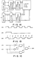
- Fig. 1A is a block diagram showing the apparatus according to the present invention.
- Fig. 1B shows how a data modulator output signal (DM) is formed, the signal being supplied to an information electrode group of the apparatus according to the present invention.
- DM data modulator output signal
- Fig. 1C is a circuit diagram of the circuit for forming the data modulator output signal (DM) shown in Fig. 1B.
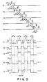
- Fig. 2 shows the waveforms of drive voltage signals used for the apparatus according to the present invention.
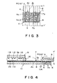
- Fig. 3 is a plan view of the apparatus according to the present invention.
- Fig. 4 is a cross section, taken along line Y-Y' of Fig. 3, of the apparatus according to the present invention.
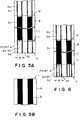
- Fig. 5A is a plan view of the substrate 8 used in the present invention.
- Fig. 5B is a plan view of the film carrier used in the present invention.
- Fig. 6 is a plan view of another substrate 8 used in the present invention.
- Fig. 7A is a plan view of an apparatus to which the present invention is not applied.
- Fig. 7B is a plan view of the substrate 8 used in the apparatus shown in Fig. 7A.
- Fig. 8 is an equivalent circuit diagram of the apparatus according to the present invention.
- Fig. 9 is an equivalent circuit diagram of the apparatus shown in Fig. 7A.
- Fig. 10 is a plan view of the apparatus according to another embodiment of the present invention.
- Fig. 11 is a plan view showing a connection between a liquid crystal panel connection electrode of the present invention and a drive IC in a bare chip state.
- Fig. 12 is a cross section taken along line y-y'.
- Fig. 1A is a schematic diagram showing the electrical system for driving a ferroelectric liquid crystal cell in the manner as illustrated in Fig. 2.
- a clock signal (CS) generated by a clock generator is supplied to a scan electrode selector for selecting a scan electrode.
- a signal outputted from the scan electrode selector is supplied to a scan electrode driver to generate a signal to be supplied to a scan electrode group.
- a data modulator capable of generating an information signal and auxiliary signal is supplied with the clock signal (CS) and a data signal (DS) outputted from a data generator.
- the data modulator generates a data modulated signal (DM) which is supplied to a signal electrode driver and then to a signal electrode group.
- Fig. 1B shows examples of signals inputted to and outputted from the data modulator.
- the output signal corresponds to the signal I1 shown in Fig. 2.
- Fig. 1C is a circuit diagram of the data modulator for outputting the data modulated signal (DM) shown in Fig. 1B.
- the modulator is constructed of two inverters 11 and 12, two AND gates 13 and 14, and an OR gate 15.
- Signals S1 to S5 shown in Fig. 2 are scan signals applied to the scan electrodes of the matrix electrode group, and correspond to the signals outputted from the scan electrode driver shown in Fig. 1A.
- Signals I1 to I3 are information signals or data modulated signals applied to the information electrodes or signal electrodes of the matrix electrode group, and correspond to the signals outputted from the information electrode driver or signal electrode driver shown in Fig. 1A.
- Letter A represents a voltage waveform of a signal at an intersection point for the signals S1 and I1
- letter C represents a voltage waveform of a signal at an intersection point for the signals S3 and I3.
- the external drive circuit of the liquid crystal apparatus shown in Fig. 1A includes a scan side drive circuit having the scan electrode selector and scan electrode driver, and an information side drive circuit having the data generator, data modulator, and signal electrode driver.
- Fig. 3 is a plan view of a substrate 8 of a liquid crystal panel 111 as viewed in the direction indicated by an arrow 114, the plan view showing the connection arrangement of the present invention.
- Fig. 4 is a cross section taken along line Y-Y' of Fig. 3.
- Fig. 7 is a plan view showing the connection arrangement to which the present invention is not applied (as viewed in the same direction as in Fig. 3).
- a connection electrode 1 of the liquid crystal panel 111 (parallel electrodes each having a line width of 100 ⁇ m and a line space of 100 ⁇ m, the plan view being shown in Fig. 5) has a two-layer structure constructed of an ITO (indium tin oxide) thin film 2a of about 500 to 1500 angstroms, and a metal thin film 3a (e.g., molybdenum, aluminum) of about 1000 to 3000 angstroms.
- the metal thin film may be a laminated film having two or more layers.
- An ITO opening area 4 having a width of 80 ⁇ m is formed in the electrode 1 at the central area thereof, and the metal thin film 3a is left at opposite ends (side edge portions).
- the liquid crystal panel 111 used in the present invention is provided with liquid crystal cells integrally formed with the substrate 8.
- the cell structure of the liquid crystal cells is provided with the substrate 8 laminated with the metal thin film 3b and ITO thin film 2b, another substrate 118 facing the substrate 8, and liquid crystal material 115.
- the substrate 118 facing the substrate 8 is formed with a metal thin film 113 intersecting with the metal thin film 3b, and ITO thin film 112.
- the cell structure is sealed with sealing material 116 at the peripheral portion between the two substrates 118 and 8.
- An isotropic conductive film is interposed between the connection electrode 1 of the liquid crystal panel 111 and a connection electrode 5 of an external drive circuit.
- the connection electrode 5 may be, for example, a connection electrode on a film carrier having a base film 9, the electrode being made of copper.
- the isotropic conductive film is made of, for example, epoxy-based adhesive agent with solder particles being dispersed. Both the electrodes are connected together by thermocompression bonding. Fine solder particles are melted and pressed through thermocompression so that they diffuse in the direction parallel to the substrate. It is therefore possible to obtain electrical contact of a large area as indicated at 7a in Fig. 3. In this case, solder particles present between the connection electrode 5 and the ITO thin film 2a (or 4) become electrical contacts 7a of a shape extending in the direction parallel to the substrate. However, solder particles not present between the connection electrode 5 and the ITO thin film are not pressed and left as solder particles 7b which do not contribute at all to electrical connection.
- connection electrode 1 of the liquid crystal panel 111 and the connection electrode 5 of the film carrier become in area contact with the solder particles 7a, providing a highly reliable electrical connection.
- the wiring resistance from the external drive circuit to the liquid crystal material 115 is reduced to a low value because of the metal thin film 3b on the connection electrode 1 of the liquid crystal panel 111.
- the blank portion 31 shown in Fig. 3 corresponds to the area where the epoxy-based adhesive agent 6 indicated by hatched lines cannot be observed when the portion with the substrate 8 and base film 9 are facing each other is viewed in the direction indicated by the arrow 114, because the metal thin film 3a formed on the substrate 8 is opaque.
- Fig. 6 shows another preferred embodiment of the present invention.
- the structure of this embodiment is the same as shown in Fig. 5 except that there are provided three narrow metal thin film 3a on an ITO thin film 2a.
- the line width of a narrow metal thin film 3a used in the present invention is preferably about 1/3 to 1/30 time as narrow as the width W of the stripe metal thin film 3c.
- the width W is generally about 50 to 500 microns.
- the metal thin film 3c at the area outside of the liquid crystal cell preferably covers the whole area of the ITO thin film.
- Figs. 7A and 7B show an apparatus to which the present invention is not applied.
- This apparatus uses the same substrate 8 shown in Fig. 5A except that the narrow metal thin film 3a used in the present invention is omitted.
- Fig. 8 is an equivalent circuit of the apparatuses shown in Figs. 3, 4, 5A and 5B.
- R2 represents a wiring resistance of the connection electrode 5 from the external drive circuit 10 to the solder particle No. 2 nearest to the external circuit 10
- R3 represents a wiring resistance of the connection electrode 5 between two adjacent solder particles
- R4 represents a wiring resistance of the ITO thin film between two adjacent solder particles
- Rb represents a wiring resistance of the narrow metal thin film 3a between two adjacent solder particles
- R7 represents a wiring resistance of the ITO thin film from the point A to the liquid crystal material
- R8 represents a wiring resistance of the metal thin film 3c from the point A to the liquid crystal.
- the values of these resistances are the same both for the apparatus of the present invention and the apparatus to which the present invention is not applied.
- a wiring resistance R12 from the external drive circuit 10 and the liquid crystal material is greatly dependent upon the distance a from the point A of the metal thin film 3c to the solder particle No. 1 nearest to the metal thin film 3c and the resistance Rito of the ITO electrode 2a.
- the sheet resistance value of the ITO electrode 2a is several tens times as large as that of the metal thin film 3c.
- the distance a varies with the dispersion degree of solder particles, and it is inevitable in many cases that the distance a takes a maximum of about 500 ⁇ m.
- connection arrangement of the present invention electrical connection is reliably obtained by means of the ITO opening area 4, and the metal thin film 3a is left at the opposite ends (side edge portions) of the connection electrode 1 of the liquid crystal panel so that the distance from the solder particle 7a to the metal thin film 3a is made several microns or less. Therefore, the above-described two problems can be eliminated.
- Fig. 10 shows the case where the connection electrode 1 of the liquid crystal panel 111 is positioned facing the connection electrode 5 of the film carrier, both the electrodes being displaced in the direction indicated by X.
- the ITO opening area 4 having a width of, e.g., 80 ⁇ m is formed in the connection electrode 1 of the liquid crystal panel 111 at the central area thereof, and a parallel pattern of metal thin films of about 10 ⁇ m runs at the opposite side edge portions of the electrode.
- the connection electrode 1 of the liquid panel 111 and the connection electrode 5 of the external drive circuit displace from each other by 10 microns for example in the direction indicated by X in Fig. 10, it is possible to obtain electrical connection without reducing the contact area and prevent the wiring resistance R1 from increasing.
- Figs. 11 and 12 show an electrical connection between a connection electrode 111 of a liquid crystal panel and a drive IC 112 of a bare chip state.
- Fig. 12 is a cross section taken along line y-y' of Fig. 11.
- the connection electrode 111 of the liquid crystal panel has a two-layer structure including an ITO thin film 113 and metal thin film 114.
- An ITO opening area 116 is formed in the connection electrode 111 at the central area thereof facing the connection electrode 115 of the drive IC 112.
- a metal bump (gold, silver, copper, or the like) 117 is formed between the ITO opening area 116 and the connection electrode 115 of the drive IC 112.
- Both the electrodes are connected together using conductive paste 118 interposed therebetween. Electrical connection is obtained at the ITO opening area 116 so that the connection reliability can be improved, and because of the presence of the metal thin film 114 near the ITO opening area the wiring resistance from the drive IC 112 to the liquid crystal material can be made small.
- reference numeral 120 represents an epoxy-based adhesive agent
- reference numeral 121 represents an insulating film such as SiO2 and polyimide.
- connection electrode of a liquid crystal panel is made to have a two-layer structure of an ITO thin film and metal thin film, and an ITO opening area is formed. Therefore, connection to the connection electrode of an external drive circuit can be obtained with high reliability, and the wiring resistance from the external drive circuit to the liquid crystal material can be made small:
- the ITO opening area is formed in the connection electrode of a liquid crystal panel at the central area thereof. Therefore, even a positional displacement relative to the external drive circuit occurs during connection work, the connection reliability can be prevented from being lowered due to a reduction of contact area.
Landscapes
- Physics & Mathematics (AREA)
- Engineering & Computer Science (AREA)
- Nonlinear Science (AREA)
- Manufacturing & Machinery (AREA)
- Microelectronics & Electronic Packaging (AREA)
- Mathematical Physics (AREA)
- Chemical & Material Sciences (AREA)
- Crystallography & Structural Chemistry (AREA)
- General Physics & Mathematics (AREA)
- Optics & Photonics (AREA)
- Liquid Crystal (AREA)
- Physical Or Chemical Processes And Apparatus (AREA)
Claims (6)
- Flüssigkristallvorrichtung, bei der eine Flüssigkristallfeld-Elektrode (1) mit einer Vielzahl von streifenförmig ausgebildeten, aus der Zelle eines Flüssigkristallfeldes (111) verlaufenden Verbindungselektroden (3c) mit einer aus einer externen Schaltung zum Ansteuern des Flüssigkristallfeldes (111) verlaufenden Externschaltungs-Elektrode (5) durch Verwenden eines leitendes Materials verbunden ist, wobei die Flüssigkristallfeld-Elektrode (1) ein aus einem Indium-Zinn-Oxid-Film (2a, 2b) und einem Metallfilm (3a, 3b, 3c) hergestellter laminierte Film ist, und wobeidie Flüssigkristallfeld-Elektrode (1) einen belassenen Abschnitt (3a) des Metallfilms (3a, 3b, 3c) und einen Indium-Zinn-Oxid-Öffnungsbereich (4) an einem Verbindungsbereich zwischen der Flüssigkristallfeld-Elektrode (1) und der Externschaltungs-Elektrode (5) aufweist,dadurch gekennzeichnet, daßder Metallfilm an dem Bereich außerhalb einer Flüssigkristallzelle den gesamten Bereich des Indium-Zinn-Oxid-Films (2a, 2b) außer dem Öffnungsbereich (4) bedeckt.
- Flüssigkristallvorrichtung nach Anspruch 1dadurch gekennzeichnet, daßder belassene Abschnitt (3a) des Metallfilms (3a, 3b, 3c) der Flüssigkristallfeld-Elektrode (1) an dem Verbindungsbereich derart ausgebildet ist, daß er eine Breite aufweist, die 1/30- bis 1/3-mal so schmal wie die Breite des Streifens (3c) ist.
- Flüssigkristallvorrichtung nach Anspruch 1,dadurch gekennzeichnet, daßder belassene Abschnitt (3a) des Metallfilms (3a, 3b, 3c) der Flüssigkristallfeld-Elektrode (1) an dem Verbindungsbereich derart ausgebildet ist, daß er eine Breite aufweist, die 1/30- bis 1/3-mal so schmal wie die Breite des Streifens (3c) entlang der Längsrichtung des Streifens (3c) an gegenüberliegenden Enden des Streifens (3c) ist.
- Flüssigkristallvorrichtung nach Anspruch 1,dadurch gekennzeichnet, daßder Metallfilm (3a, 3b, 3c) ein Molybdänfilm ist.
- Flüssigkristallvorrichtung nach Anspruch 1,dadurch gekennzeichnet, daßdas leitende Material Metallpartikel enthält.
- Flüssigkristallvorrichtung nach Anspruch 1,dadurch gekennzeichnet, daßdas leitende Material mit Metall plattierte Harzpartikel enthält.
Applications Claiming Priority (4)
| Application Number | Priority Date | Filing Date | Title |
|---|---|---|---|
| JP241164/90 | 1990-09-13 | ||
| JP24116490 | 1990-09-13 | ||
| JP215272/90 | 1991-08-27 | ||
| JP3215272A JPH0540274A (ja) | 1990-09-13 | 1991-08-27 | 液晶装置 |
Publications (3)
| Publication Number | Publication Date |
|---|---|
| EP0475402A2 EP0475402A2 (de) | 1992-03-18 |
| EP0475402A3 EP0475402A3 (en) | 1992-08-12 |
| EP0475402B1 true EP0475402B1 (de) | 1996-04-10 |
Family
ID=26520779
Family Applications (1)
| Application Number | Title | Priority Date | Filing Date |
|---|---|---|---|
| EP91115463A Expired - Lifetime EP0475402B1 (de) | 1990-09-13 | 1991-09-12 | Flüssigkristallgerät |
Country Status (6)
| Country | Link |
|---|---|
| US (1) | US5270848A (de) |
| EP (1) | EP0475402B1 (de) |
| JP (1) | JPH0540274A (de) |
| AT (1) | ATE136657T1 (de) |
| DE (1) | DE69118624T2 (de) |
| ES (1) | ES2087935T3 (de) |
Families Citing this family (28)
| Publication number | Priority date | Publication date | Assignee | Title |
|---|---|---|---|---|
| DE69323597T2 (de) * | 1992-11-12 | 1999-08-19 | Canon K.K. | Flüssigkristall-Anzeigevorrichtung |
| US5467210A (en) * | 1993-02-16 | 1995-11-14 | Casio Computer Co., Ltd. | Arrangement of bonding IC chip to liquid crystal display device |
| US6437846B1 (en) * | 1993-03-15 | 2002-08-20 | Seiko Epson Corporation | Liquid crystal display device and electronic device including same |
| JP3184853B2 (ja) * | 1993-06-24 | 2001-07-09 | 株式会社日立製作所 | 液晶表示装置 |
| US7081938B1 (en) | 1993-12-03 | 2006-07-25 | Semiconductor Energy Laboratory Co., Ltd. | Electro-optical device and method for manufacturing the same |
| TW340192B (en) * | 1993-12-07 | 1998-09-11 | Sharp Kk | A display board having wiring with three-layered structure and a display device including the display board |
| US5798811A (en) * | 1993-12-21 | 1998-08-25 | U.S. Philips Corporation | Picture display device with partially clear contact areas |
| EP0685099A1 (de) * | 1993-12-21 | 1995-12-06 | Koninklijke Philips Electronics N.V. | Bildanzeigevorrichtung und herstellungsverfahren |
| TW281855B (en) * | 1993-12-21 | 1996-07-21 | Sharp Kk | Panel assembly structure and panel assembling method capable of achieving a highly reliable connection of electrode terminals even when the electrode terminals have a fine pitch |
| JP3256391B2 (ja) * | 1994-11-28 | 2002-02-12 | キヤノン株式会社 | 回路基板構造 |
| EP1211663A1 (de) * | 1994-12-14 | 2002-06-05 | Canon Kabushiki Kaisha | Anzeigeinrichtung mit Massenleitungen mit niedriger elektromagnetischer Induktion |
| KR0139374B1 (ko) * | 1994-12-30 | 1998-06-15 | 김광호 | 박막 트랜지스터 액정표시패널의 트랜스퍼 컨택트 형성방법 및 그 구조 |
| US5808707A (en) * | 1995-03-01 | 1998-09-15 | Canon Kabushiki Kaisha | Display apparatus |
| US5936850A (en) * | 1995-03-03 | 1999-08-10 | Canon Kabushiki Kaisha | Circuit board connection structure and method, and liquid crystal device including the connection structure |
| JP3139601B2 (ja) * | 1995-03-08 | 2001-03-05 | キヤノン株式会社 | 液晶表示装置 |
| US5903251A (en) * | 1996-01-29 | 1999-05-11 | Canon Kabushiki Kaisha | Liquid crystal apparatus that changes a voltage level of a correction pulse based on a detected temperature |
| US6738123B1 (en) | 1996-03-15 | 2004-05-18 | Canon Kabushiki Kaisha | Drive circuit connection structure including a substrate, circuit board, and semiconductor device, and display apparatus including the connection structure |
| US5864377A (en) * | 1996-11-18 | 1999-01-26 | Samsung Electronics Co., Ltd. | Liquid crystal display |
| US6081309A (en) * | 1997-08-28 | 2000-06-27 | Canon Kabushiki Kaisha | Liquid crystal device |
| JPH11160734A (ja) * | 1997-11-28 | 1999-06-18 | Semiconductor Energy Lab Co Ltd | 液晶電気光学装置 |
| JP2000347207A (ja) * | 1999-06-04 | 2000-12-15 | Nec Corp | 液晶表示装置及び液晶表示装置の製造方法 |
| JP3535799B2 (ja) | 2000-03-30 | 2004-06-07 | キヤノン株式会社 | 液晶表示装置およびその駆動方法 |
| JP3486599B2 (ja) | 2000-03-31 | 2004-01-13 | キヤノン株式会社 | 液晶素子の駆動方法 |
| GB2366669A (en) | 2000-08-31 | 2002-03-13 | Nokia Mobile Phones Ltd | Connector for liquid crystal display |
| US6501525B2 (en) * | 2000-12-08 | 2002-12-31 | Industrial Technology Research Institute | Method for interconnecting a flat panel display having a non-transparent substrate and devices formed |
| US20030107690A1 (en) * | 2001-12-12 | 2003-06-12 | Hirohiko Nishiki | System and method for ozone cleaning a liquid crystal display structure |
| WO2005010599A1 (en) * | 2003-07-29 | 2005-02-03 | Koninklijke Philips Electronics N.V. | Electronic apparatus with a wiring terminal |
| US8049862B2 (en) * | 2008-08-08 | 2011-11-01 | Apple Inc. | Indium tin oxide (ITO) layer forming |
Family Cites Families (8)
| Publication number | Priority date | Publication date | Assignee | Title |
|---|---|---|---|---|
| JPS59129833A (ja) * | 1983-01-17 | 1984-07-26 | Hitachi Ltd | 液晶表示素子 |
| GB2153575B (en) * | 1983-12-16 | 1988-07-27 | Citizen Watch Co Ltd | Liquid crystal display device |
| JPS61174507A (ja) * | 1985-01-30 | 1986-08-06 | Hitachi Ltd | 液晶表示素子 |
| JPS63316885A (ja) * | 1987-06-19 | 1988-12-26 | キヤノン株式会社 | 液晶装置及び液晶パネルの接続法 |
| JPS6432233A (en) * | 1987-07-28 | 1989-02-02 | Sharp Kk | Liquid crystal display device |
| DE3851223T2 (de) * | 1988-05-03 | 1994-12-22 | Copytele Inc | Monolithische Flachtafel-Anzeigevorrichtung. |
| JPH0740496B2 (ja) * | 1989-03-01 | 1995-05-01 | シャープ株式会社 | 電極上への導電性粒子の配置方法 |
| JPH03125443A (ja) * | 1989-10-09 | 1991-05-28 | Sharp Corp | 実装基板の電極及び該実装基板の電極を有する液晶表示装置 |
-
1991
- 1991-08-27 JP JP3215272A patent/JPH0540274A/ja active Pending
- 1991-09-12 DE DE69118624T patent/DE69118624T2/de not_active Expired - Fee Related
- 1991-09-12 US US07/757,987 patent/US5270848A/en not_active Expired - Fee Related
- 1991-09-12 ES ES91115463T patent/ES2087935T3/es not_active Expired - Lifetime
- 1991-09-12 AT AT91115463T patent/ATE136657T1/de not_active IP Right Cessation
- 1991-09-12 EP EP91115463A patent/EP0475402B1/de not_active Expired - Lifetime
Also Published As
| Publication number | Publication date |
|---|---|
| ATE136657T1 (de) | 1996-04-15 |
| EP0475402A3 (en) | 1992-08-12 |
| DE69118624D1 (de) | 1996-05-15 |
| EP0475402A2 (de) | 1992-03-18 |
| JPH0540274A (ja) | 1993-02-19 |
| DE69118624T2 (de) | 1996-09-19 |
| US5270848A (en) | 1993-12-14 |
| ES2087935T3 (es) | 1996-08-01 |
Similar Documents
| Publication | Publication Date | Title |
|---|---|---|
| EP0475402B1 (de) | Flüssigkristallgerät | |
| US4985663A (en) | Display device | |
| US20060103802A1 (en) | Liquid crystal display device sealed with liquid crystal seal composed of anisotropic conductive material | |
| EP0795772B1 (de) | Kontaktierungsstruktur für Treiberschaltung und Anzeigevorrichtung mit dieser Kontaktierungsstruktur | |
| EP0422906B1 (de) | Elektroden auf einem Montagesubstrat und Flüssigkristallanzeigevorrichtung, die dieses enthält | |
| US4295711A (en) | Liquid crystal display device | |
| JP3711398B2 (ja) | 配線基板 | |
| JPS63184781A (ja) | 液晶表示装置 | |
| JP4554983B2 (ja) | 液晶表示装置 | |
| JP3340005B2 (ja) | 液晶表示装置 | |
| JPH08297291A (ja) | フリップチップ方式の液晶表示素子 | |
| JP3323692B2 (ja) | フリップチップ方式の液晶表示素子 | |
| JPH09101533A (ja) | 液晶表示装置 | |
| JP3198162B2 (ja) | 半導体集積回路装置の接続方法 | |
| JP2008090147A (ja) | 接続端子基板及びこれを用いた電子装置 | |
| JPH0325419A (ja) | 液晶表示装置 | |
| JPH11297759A (ja) | 半導体チップの実装構造および液晶表示装置 | |
| JPH04217228A (ja) | 液晶表示装置 | |
| JPS5834487A (ja) | 平板表示装置 | |
| JPH08293656A (ja) | 配線接続構造 | |
| JP3088514B2 (ja) | Icカード用液晶表示装置 | |
| JPH09305121A (ja) | 回路接続構造、この回路接続構造を有する表示装置及びtcp構造体 | |
| JP2600166B2 (ja) | 反射型液晶表示デバイス | |
| JPS62182790A (ja) | 液晶表示装置 | |
| JPH05196953A (ja) | 配線フィルムの接続方法 |
Legal Events
| Date | Code | Title | Description |
|---|---|---|---|
| PUAI | Public reference made under article 153(3) epc to a published international application that has entered the european phase |
Free format text: ORIGINAL CODE: 0009012 |
|
| AK | Designated contracting states |
Kind code of ref document: A2 Designated state(s): AT BE CH DE DK ES FR GB GR IT LI LU NL SE |
|
| PUAL | Search report despatched |
Free format text: ORIGINAL CODE: 0009013 |
|
| AK | Designated contracting states |
Kind code of ref document: A3 Designated state(s): AT BE CH DE DK ES FR GB GR IT LI LU NL SE |
|
| 17P | Request for examination filed |
Effective date: 19921229 |
|
| 17Q | First examination report despatched |
Effective date: 19940712 |
|
| GRAA | (expected) grant |
Free format text: ORIGINAL CODE: 0009210 |
|
| AK | Designated contracting states |
Kind code of ref document: B1 Designated state(s): AT BE CH DE DK ES FR GB GR IT LI LU NL SE |
|
| PG25 | Lapsed in a contracting state [announced via postgrant information from national office to epo] |
Ref country code: GR Free format text: LAPSE BECAUSE OF FAILURE TO SUBMIT A TRANSLATION OF THE DESCRIPTION OR TO PAY THE FEE WITHIN THE PRESCRIBED TIME-LIMIT Effective date: 19960410 Ref country code: DK Effective date: 19960410 Ref country code: AT Effective date: 19960410 |
|
| REF | Corresponds to: |
Ref document number: 136657 Country of ref document: AT Date of ref document: 19960415 Kind code of ref document: T |
|
| REF | Corresponds to: |
Ref document number: 69118624 Country of ref document: DE Date of ref document: 19960515 |
|
| ET | Fr: translation filed | ||
| ITF | It: translation for a ep patent filed | ||
| REG | Reference to a national code |
Ref country code: ES Ref legal event code: BA2A Ref document number: 2087935 Country of ref document: ES Kind code of ref document: T3 |
|
| REG | Reference to a national code |
Ref country code: CH Ref legal event code: NV Representative=s name: BOVARD AG PATENTANWAELTE |
|
| REG | Reference to a national code |
Ref country code: ES Ref legal event code: FG2A Ref document number: 2087935 Country of ref document: ES Kind code of ref document: T3 |
|
| GRAH | Despatch of communication of intention to grant a patent |
Free format text: ORIGINAL CODE: EPIDOS IGRA |
|
| PG25 | Lapsed in a contracting state [announced via postgrant information from national office to epo] |
Ref country code: LU Free format text: LAPSE BECAUSE OF NON-PAYMENT OF DUE FEES Effective date: 19960930 |
|
| PLBE | No opposition filed within time limit |
Free format text: ORIGINAL CODE: 0009261 |
|
| STAA | Information on the status of an ep patent application or granted ep patent |
Free format text: STATUS: NO OPPOSITION FILED WITHIN TIME LIMIT |
|
| 26N | No opposition filed | ||
| REG | Reference to a national code |
Ref country code: GB Ref legal event code: IF02 |
|
| PGFP | Annual fee paid to national office [announced via postgrant information from national office to epo] |
Ref country code: NL Payment date: 20040905 Year of fee payment: 14 |
|
| PGFP | Annual fee paid to national office [announced via postgrant information from national office to epo] |
Ref country code: SE Payment date: 20040906 Year of fee payment: 14 |
|
| PGFP | Annual fee paid to national office [announced via postgrant information from national office to epo] |
Ref country code: GB Payment date: 20040908 Year of fee payment: 14 Ref country code: FR Payment date: 20040908 Year of fee payment: 14 |
|
| PGFP | Annual fee paid to national office [announced via postgrant information from national office to epo] |
Ref country code: DE Payment date: 20040909 Year of fee payment: 14 |
|
| PGFP | Annual fee paid to national office [announced via postgrant information from national office to epo] |
Ref country code: CH Payment date: 20040915 Year of fee payment: 14 |
|
| PGFP | Annual fee paid to national office [announced via postgrant information from national office to epo] |
Ref country code: ES Payment date: 20040929 Year of fee payment: 14 |
|
| PGFP | Annual fee paid to national office [announced via postgrant information from national office to epo] |
Ref country code: BE Payment date: 20041122 Year of fee payment: 14 |
|
| PG25 | Lapsed in a contracting state [announced via postgrant information from national office to epo] |
Ref country code: IT Free format text: LAPSE BECAUSE OF NON-PAYMENT OF DUE FEES Effective date: 20050912 Ref country code: GB Free format text: LAPSE BECAUSE OF NON-PAYMENT OF DUE FEES Effective date: 20050912 |
|
| PG25 | Lapsed in a contracting state [announced via postgrant information from national office to epo] |
Ref country code: SE Free format text: LAPSE BECAUSE OF NON-PAYMENT OF DUE FEES Effective date: 20050913 Ref country code: ES Free format text: LAPSE BECAUSE OF NON-PAYMENT OF DUE FEES Effective date: 20050913 |
|
| PG25 | Lapsed in a contracting state [announced via postgrant information from national office to epo] |
Ref country code: LI Free format text: LAPSE BECAUSE OF NON-PAYMENT OF DUE FEES Effective date: 20050930 Ref country code: CH Free format text: LAPSE BECAUSE OF NON-PAYMENT OF DUE FEES Effective date: 20050930 Ref country code: BE Free format text: LAPSE BECAUSE OF NON-PAYMENT OF DUE FEES Effective date: 20050930 |
|
| PG25 | Lapsed in a contracting state [announced via postgrant information from national office to epo] |
Ref country code: NL Free format text: LAPSE BECAUSE OF NON-PAYMENT OF DUE FEES Effective date: 20060401 Ref country code: DE Free format text: LAPSE BECAUSE OF NON-PAYMENT OF DUE FEES Effective date: 20060401 |
|
| REG | Reference to a national code |
Ref country code: CH Ref legal event code: PL |
|
| EUG | Se: european patent has lapsed | ||
| GBPC | Gb: european patent ceased through non-payment of renewal fee |
Effective date: 20050912 |
|
| PG25 | Lapsed in a contracting state [announced via postgrant information from national office to epo] |
Ref country code: FR Free format text: LAPSE BECAUSE OF NON-PAYMENT OF DUE FEES Effective date: 20060531 |
|
| NLV4 | Nl: lapsed or anulled due to non-payment of the annual fee |
Effective date: 20060401 |
|
| REG | Reference to a national code |
Ref country code: FR Ref legal event code: ST Effective date: 20060531 |
|
| REG | Reference to a national code |
Ref country code: ES Ref legal event code: FD2A Effective date: 20050913 |
|
| BERE | Be: lapsed |
Owner name: *CANON K.K. Effective date: 20050930 |