EP0474423B1 - Primary air system for a melt blown die apparatus - Google Patents
Primary air system for a melt blown die apparatus Download PDFInfo
- Publication number
- EP0474423B1 EP0474423B1 EP91307843A EP91307843A EP0474423B1 EP 0474423 B1 EP0474423 B1 EP 0474423B1 EP 91307843 A EP91307843 A EP 91307843A EP 91307843 A EP91307843 A EP 91307843A EP 0474423 B1 EP0474423 B1 EP 0474423B1
- Authority
- EP
- European Patent Office
- Prior art keywords
- die
- air
- tubular chamber
- polymer
- pressurized gas
- Prior art date
- Legal status (The legal status is an assumption and is not a legal conclusion. Google has not performed a legal analysis and makes no representation as to the accuracy of the status listed.)
- Expired - Lifetime
Links
- 239000000155 melt Substances 0.000 title claims description 11
- 229920000642 polymer Polymers 0.000 claims abstract description 39
- 238000009826 distribution Methods 0.000 claims abstract description 9
- 239000002861 polymer material Substances 0.000 claims abstract description 7
- 238000005452 bending Methods 0.000 abstract description 6
- 238000010276 construction Methods 0.000 abstract description 3
- 239000007789 gas Substances 0.000 description 31
- 229920005989 resin Polymers 0.000 description 19
- 239000011347 resin Substances 0.000 description 19
- 238000013461 design Methods 0.000 description 17
- 238000000034 method Methods 0.000 description 16
- 238000001125 extrusion Methods 0.000 description 11
- 239000000835 fiber Substances 0.000 description 10
- 239000004743 Polypropylene Substances 0.000 description 7
- -1 polypropylene Polymers 0.000 description 7
- 229920001155 polypropylene Polymers 0.000 description 7
- 125000006850 spacer group Chemical group 0.000 description 6
- 238000001914 filtration Methods 0.000 description 5
- 238000010438 heat treatment Methods 0.000 description 4
- 238000004519 manufacturing process Methods 0.000 description 4
- 239000008188 pellet Substances 0.000 description 4
- 238000007789 sealing Methods 0.000 description 4
- 230000036961 partial effect Effects 0.000 description 3
- 241000239290 Araneae Species 0.000 description 2
- IJGRMHOSHXDMSA-UHFFFAOYSA-N Atomic nitrogen Chemical compound N#N IJGRMHOSHXDMSA-UHFFFAOYSA-N 0.000 description 2
- 229920001410 Microfiber Polymers 0.000 description 2
- 230000006835 compression Effects 0.000 description 2
- 238000007906 compression Methods 0.000 description 2
- 238000001816 cooling Methods 0.000 description 2
- 229910052802 copper Inorganic materials 0.000 description 2
- 239000010949 copper Substances 0.000 description 2
- 230000000694 effects Effects 0.000 description 2
- 239000011888 foil Substances 0.000 description 2
- 239000008187 granular material Substances 0.000 description 2
- 238000009413 insulation Methods 0.000 description 2
- 230000001788 irregular Effects 0.000 description 2
- 239000003658 microfiber Substances 0.000 description 2
- 229920005594 polymer fiber Polymers 0.000 description 2
- RYGMFSIKBFXOCR-UHFFFAOYSA-N Copper Chemical compound [Cu] RYGMFSIKBFXOCR-UHFFFAOYSA-N 0.000 description 1
- 239000004677 Nylon Substances 0.000 description 1
- 239000004952 Polyamide Substances 0.000 description 1
- 238000013459 approach Methods 0.000 description 1
- 230000000712 assembly Effects 0.000 description 1
- 238000000429 assembly Methods 0.000 description 1
- QVGXLLKOCUKJST-UHFFFAOYSA-N atomic oxygen Chemical compound [O] QVGXLLKOCUKJST-UHFFFAOYSA-N 0.000 description 1
- 230000002238 attenuated effect Effects 0.000 description 1
- 238000007664 blowing Methods 0.000 description 1
- 230000001419 dependent effect Effects 0.000 description 1
- 238000006073 displacement reaction Methods 0.000 description 1
- 238000001035 drying Methods 0.000 description 1
- 230000008030 elimination Effects 0.000 description 1
- 238000003379 elimination reaction Methods 0.000 description 1
- 238000005516 engineering process Methods 0.000 description 1
- 239000004744 fabric Substances 0.000 description 1
- 239000012530 fluid Substances 0.000 description 1
- 239000012943 hotmelt Substances 0.000 description 1
- 230000000670 limiting effect Effects 0.000 description 1
- 238000003754 machining Methods 0.000 description 1
- 238000012423 maintenance Methods 0.000 description 1
- 239000000463 material Substances 0.000 description 1
- 238000002844 melting Methods 0.000 description 1
- 230000008018 melting Effects 0.000 description 1
- 238000012986 modification Methods 0.000 description 1
- 230000004048 modification Effects 0.000 description 1
- 229910052757 nitrogen Inorganic materials 0.000 description 1
- 229920001778 nylon Polymers 0.000 description 1
- 230000003647 oxidation Effects 0.000 description 1
- 238000007254 oxidation reaction Methods 0.000 description 1
- 239000001301 oxygen Substances 0.000 description 1
- 229910052760 oxygen Inorganic materials 0.000 description 1
- 239000004033 plastic Substances 0.000 description 1
- 229920002647 polyamide Polymers 0.000 description 1
- 229920000098 polyolefin Polymers 0.000 description 1
- 230000002028 premature Effects 0.000 description 1
- 230000000135 prohibitive effect Effects 0.000 description 1
- 238000005086 pumping Methods 0.000 description 1
- 238000010926 purge Methods 0.000 description 1
- 238000003908 quality control method Methods 0.000 description 1
- 238000010791 quenching Methods 0.000 description 1
- 230000000171 quenching effect Effects 0.000 description 1
- 230000002829 reductive effect Effects 0.000 description 1
- 230000001105 regulatory effect Effects 0.000 description 1
- 238000009987 spinning Methods 0.000 description 1
- 229910001220 stainless steel Inorganic materials 0.000 description 1
- 239000010935 stainless steel Substances 0.000 description 1
- 229920005992 thermoplastic resin Polymers 0.000 description 1
- 238000012546 transfer Methods 0.000 description 1
Images

Classifications
-
- D—TEXTILES; PAPER
- D01—NATURAL OR MAN-MADE THREADS OR FIBRES; SPINNING
- D01D—MECHANICAL METHODS OR APPARATUS IN THE MANUFACTURE OF ARTIFICIAL FILAMENTS, THREADS, FIBRES, BRISTLES OR RIBBONS
- D01D4/00—Spinnerette packs; Cleaning thereof
- D01D4/02—Spinnerettes
-
- D—TEXTILES; PAPER
- D01—NATURAL OR MAN-MADE THREADS OR FIBRES; SPINNING
- D01D—MECHANICAL METHODS OR APPARATUS IN THE MANUFACTURE OF ARTIFICIAL FILAMENTS, THREADS, FIBRES, BRISTLES OR RIBBONS
- D01D5/00—Formation of filaments, threads, or the like
- D01D5/08—Melt spinning methods
- D01D5/098—Melt spinning methods with simultaneous stretching
- D01D5/0985—Melt spinning methods with simultaneous stretching by means of a flowing gas (e.g. melt-blowing)
-
- D—TEXTILES; PAPER
- D01—NATURAL OR MAN-MADE THREADS OR FIBRES; SPINNING
- D01D—MECHANICAL METHODS OR APPARATUS IN THE MANUFACTURE OF ARTIFICIAL FILAMENTS, THREADS, FIBRES, BRISTLES OR RIBBONS
- D01D4/00—Spinnerette packs; Cleaning thereof
- D01D4/02—Spinnerettes
- D01D4/025—Melt-blowing or solution-blowing dies
-
- D—TEXTILES; PAPER
- D04—BRAIDING; LACE-MAKING; KNITTING; TRIMMINGS; NON-WOVEN FABRICS
- D04H—MAKING TEXTILE FABRICS, e.g. FROM FIBRES OR FILAMENTARY MATERIAL; FABRICS MADE BY SUCH PROCESSES OR APPARATUS, e.g. FELTS, NON-WOVEN FABRICS; COTTON-WOOL; WADDING ; NON-WOVEN FABRICS FROM STAPLE FIBRES, FILAMENTS OR YARNS, BONDED WITH AT LEAST ONE WEB-LIKE MATERIAL DURING THEIR CONSOLIDATION
- D04H1/00—Non-woven fabrics formed wholly or mainly of staple fibres or like relatively short fibres
- D04H1/40—Non-woven fabrics formed wholly or mainly of staple fibres or like relatively short fibres from fleeces or layers composed of fibres without existing or potential cohesive properties
- D04H1/54—Non-woven fabrics formed wholly or mainly of staple fibres or like relatively short fibres from fleeces or layers composed of fibres without existing or potential cohesive properties by welding together the fibres, e.g. by partially melting or dissolving
- D04H1/56—Non-woven fabrics formed wholly or mainly of staple fibres or like relatively short fibres from fleeces or layers composed of fibres without existing or potential cohesive properties by welding together the fibres, e.g. by partially melting or dissolving in association with fibre formation, e.g. immediately following extrusion of staple fibres
Definitions
- This invention relates to melt blown processes for the production of micro-denier fibrous webs from polymer stock, and more particularly, to the means for providing compressed gases directed to attenuate melt blown polymer fibers for high strength as they exit the nosepiece of the die.
- the feed stock used for melt blown procedures is typically a thermoplastic resin in the form of pellets or granules which are fed into the hopper of an extruder.
- the pellets are then introduced into a heated chamber of the extruder in which multiple heating zones raise the temperature of the resin above its melting point.
- the screw of the extruder is usually driven by a motor which moves the resin through the heating zones and into and through a die.
- the die which is also heated, raises the temperature of the resin and the chamber to a desired level, at which point, the resin is forced through a plurality of minute orifices in the face of the die.
- a pressurized hot gas usually air, which is forced into the apparatus through air discharge channels located on either side of the resin orifices.
- the hot gas attenuates the molten resin streams into fibers as the resin passes out of the orifices.
- baffles for providing uniform flows of gas at the exit end of melt-blown dies. See Lohkamp, et al., U.S. 3,825,379, July 23, 1974. More recently, air chambers have been bolted to the outside sides of the die body halves to provide compressed air through air discharge channels having a tortuous air passage including male air deflector blocks. See Buehning, U.S. 4,818,463, April 4, 1989.
- a melt blow die apparatus comprising a gas distributing system.
- the system contains a tubular chamber for receiving and distributing pressurised gas into a plenum chamber from which the gas is directed to the spinning die
- the apparatus includes a die for producing a molten stream of polymer and primary gas means for providing a pressurized gas at an exit end of the die.
- the primary gas means includes a tubular chamber for receiving and distributing the pressurized gas along a first dimension of the die.
- the tubular chamber includes an air inlet portion disposed in a first end of said tubular chamber, an air exit portion and a discharge channel for receiving the distributed pressurized gas from the tubular chamber and for directing the pressurized gas to the molten polymer stream at the exit end of the die.
- the tubular chamber includes a pressure controlled diverter for providing a substantially even gas pressure distribution across the first dimension of the die.
- the pressure control diverter comprises a pressure control diverter member disposed within the tubular chamber, the pressure control diverter member forming a minimum air gap with an inner wall portion of the tubular chamber about at a mid point thereof and a maximum air gap at about said first end of said tubular chamber.
- the unique aerodynamic design of the primary air system of this invention results in very low inlet air pressures of up to about 240 kPa (20 psig) for producing very high air flows of about 90-200 kg of air per kg of polymer at 0.72 kg per linear die cm (4.0 pounds per linear inch of die) per minute.
- the air flow temperature drop due to aerodynamic losses is minimized by the flow through structure of the primary air chambers of this invention to less than about 28°C (50°F) with attendant energy savings for operators.
- the air boxes and air manifolds support members of this invention can be mounted on horizontal supporting surfaces of the main die body halves for increasing dimensional stability of the slot width and set back dimensions by minimizing bending moments.
- This integral design can also provide thermal stability by including individual heating elements for uniformly heating the entire mass and by insulating the structure to prevent the loss of thermal energy.
- This invention provides a melt-blown die apparatus for producing a fibrous web from a polymer material which includes a die for providing a molten stream of the polymer material and primary gas means for providing a pressurized gas at an exit end of the die.
- the primary gas means includes a tubular chamber for receiving and distributing the pressurized gas along a first dimension of the die.
- the tubular chamber comprises a discharge channel for receiving the distributed pressurized gas from the tubular chamber and for directing the pressurized gas to the molten polymer stream, wherein the tubular chamber comprises a pressure control diverter for providing a substantially even gas pressure distribution across the first dimension of the die.
- substantially even gas pressure distribution means that the gas pressure along the tubular chamber does not vary more than 25%, preferably less than 10%, between any two points along the first dimension.
- a melt-blown die apparatus which comprises a die having a pair of substantially horizontal supporting surfaces and a plurality of orifices for providing a molten extrusion of a polymer material.
- the apparatus also includes primary air means for providing pressurized air at an exit end of the die for solidifying and attenuating the molten polymer extrusion into high strength microfibers.
- the primary air means of this embodiment includes a pair of air box means, each containing a tubular chamber for receiving and distributing the pressurized air along the width of the die.
- Each of these tubular chambers includes opposing air discharge channels for receiving the distributed pressurized air from the tubular chambers and for directing the pressurized air to the molten polymer extrusion.
- the air box means of this embodiment is substantially supported by the substantially horizontal supporting surfaces of the die.
- substantially supported means that a significant amount of the weight of the air box means is supported by the horizontal supporting surface of the die so as to minimize bending moments and distortion along the air discharge channels for maintaining substantially controlled set back and slot width dimensions.
- This invention also provides a method of operating a melt-blown die apparatus for producing micro-denier polymer fibers.
- the method includes providing a melt-blown die apparatus comprising a die for providing a molten extrusion of the polymer and primary air means for providing pressurized air at an exit end of the die.
- the primary air means comprises a tubular chamber for receiving and distributing the pressurized air along a width of the die.
- the tubular chamber in turn, comprises a discharge channel for receiving and distributing pressurized air from the tubular chamber and for directing the pressurized air to the molten polymer extrusion for solidifying and attenuating the extrusion.
- the tubular chamber of this apparatus includes a pressure control diverter for providing a substantially even air pressure distribution across the die width.
- the method includes the step of operating the melt-blown die apparatus at an exit air pressure of up to about 200 kg of gas per kg of polymer at a polymer flow rate of about 0.72 kg per linear die cm (4.0 lbs. per linear die inch) per minute and an air inlet pressure of less than about 240 kPa (20 psig).
- melt blown process is a manufacturing method for producing a fibrous web using a single process which converts polymer pellets directly into micro-denier fibers.
- the key elements are the polymer feed system, air supply system, die and web collection system. Preferred embodiments for these systems will now be described.
- the polymer feed system preferably involves resin handling, extrusion, extrudate filtration and metering or pumping.
- the resin pellets or granules are loaded into a hopper that supplies a feed throat portion of the extruder.
- the hopper may have drying and oxygen elimination equipment depending on the resin employed.
- the most common resin chosen is polypropylene which sometimes requires a nitrogen purge for minimizing oxidation.
- the resins of this invention are fiber grades with melt flow indexes (MFI) of about 35-1200.
- MFI melt flow indexes
- the most preferred resin is a 35 MFI polypropylene.
- the preferred extruder for the melt blown operation of this invention is a single screw device with a length to diameter ratio (L/D) range of about 24-32, preferably about 30. Twin screw units, melter pot systems and other variations are also acceptable.
- the single screw extrusion feed ports are preferably jacketed for cooling.
- the extruder screw design is resin dependent, although general application screws for polyolefins, such as polypropylene, or polyamides, such as nylon, are preferred.
- the extruder also can include barrel temperature controls, such as Proportional-Differential-Integral (PID) (heat and cooling -on/off) controllers which employ discrete units, PLC or microprocessor configurations.
- PID Proportional-Differential-Integral
- a preferred extruder barrel temperature profile for a four zone unit is 204-260-274-274°C (400-500-525-525°F) for the 35 MFI polypropylene resin.
- Screw rotation can be provided by a motor through a gear box to the screw. DC motor systems and belt drive units are preferably used for this purpose.
- the speed of the extruder screw is used to maintain a set pressure at the metering pump inlet.
- the inlet pressures for melt blowing polypropylene are preferably about 3549 to 13891 kPa (500 to 2000 psig), more preferably about 6306 kPa (900 psig).
- a melt temperature of about 288°C (550°F) is ideal for operability.
- a pressure feedback loop sensor is preferably placed directly into the flow stream for better control.
- melt blown processes require filtration of the polymer melt.
- Cartridge filters, screen packs, and other means can be employed, although this invention preferably uses a 150 micrometer cartridge filter system, for polypropylene.
- the filter as well as all interconnecting piping for the polymer stream is heated with electrically heated bands, or a hot fluid system, and controlled by a PID (heat only on/off) system.
- PID heat only on/off
- Typical temperatures employed by this invention are 288°C (550°F) for the filter and 288°C (550°F) for the piping.
- melt pump preferably a positive displacement gear-type pump.
- This pump provides the pressure and flow control necessary for quality die operation.
- the inlet pressure to the pump is controlled by extruder speed pressure feedback.
- the speed of the pump is controlled by a DC motor system through a gear box and linkage, such as a universal shaft, to the pump.
- the pump temperature is preferably controlled with electrical power PID (heat only on/off) control to obtain a melt temperature of about 288°C (550°F) for polypropylene extrusion.
- Die inlet pressures of about 2170 to 6996 kPa (300 to 1000 psig) result with a flow rate of about 0.72 kg per linear die cm (4.0 pounds per linear inch of die) per minute.
- the primary air supply system involves the compression of a gas, preferably plant air or external air, with minimal filtration.
- the pressurized air is preferably electrically heated directly, or indirectly, with a gas or oil fired furnace, to a controlled temperature.
- the now heated and pressurized air is metered to the die. Metering is done through pressure regulating valves, although true flow control units could also be used.
- Preferred air temperatures at the die inlet are about 260 to 343°C (500 to 650°F), more preferably about 288°C (550°F).
- the temperature and pressure at the die inlet are strong functions of the pressure drop through the die and the resultant temperature drop through the system.
- the preferred air flow path chosen for the primary air supply system of this invention is an open design with no substantial obstructions or balancing members.
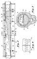
- the only interruption in the path are air foils 26 surrounding each of the supporting bolts 28 for the preferred primary air discharge channel 30.
- This unique aerodynamic design and proven method of fabrication has resulted in very low inlet air pressures of up to about 240 kPa (20 psig), and preferably about 170 to 205 kPa (10-15 psig), for producing very high air flows, e.g., about 90-200 kg of air per kg of polymer at about 0.72 kg per linear cm/minute (4.0 pounds/linear inch/minute). These parameters permit product and process extensions where prior art equipment was limited.
- the air flow temperature drop due to aerodynamic losses is minimized to less than about 28°C (50°F), preferably about 14°C (25°F) as opposed to greater than about a 56°C (100°F) drop in commercially available units.
- the lower temperature and pressure requirements of this invention produce significant energy savings for the operating plant and thus allow for economical operation for otherwise questionable process.
- the air enters the die 10 via four inlets into a pair of cylindrical tubular chambers 34.
- Each cylindrical chamber 34 is fitted with a pressure control diverter member 32 which assures even pressure distribution and mass uniformity across the die width.
- the diverter member 32 has a minimum gap 36 at about the die center and a maximum gap 38 at the ends or "entrances" of each chamber 34.
- the air passes through a series of holes 40, further illustrated in FIG. 4, at the top of the chambers 34 above the diverter member 32 to fill torroidal sections 42, separated by support ring 90, along the die width. The flow then fills the elongated angular discharge channels 30, as shown in FIG.
- the air meets the polymer strands and then exits the die 10 via a rectangular channel or sharp edge.
- the air flow channel member surfaces are aerodynamically tuned for a given set of set back and slot width dimensions.
- the air flow path width is preferably wider than the nosepiece 12 active width. This design also minimizes the negative edge or end effects.
- the air box, or air manifold support member is typically supported outboard of the main die body halves in the prior art.
- This mounting technique can cause bending moments in the air discharge channel and irregular slot width and set back spacing.
- the unique design of one embodiment of this invention uses the mass and stability of the main die body halves to support the air box 44 for minimizing bending moments.
- This integral design allows for heat transfer between these members and enables facilitated insulating of both the air box 44 and the main die body halves of the die 10.
- the integral design also provides thermal and structural integrity to the die assembly, thus allowing both dimensional and thermal stability.
- the preferred design of this invention employs two sets of heat zones.
- the first set preferably comprising electrical resistance heaters 48 and thermocouples 52, provides heat close to the coat hanger section 46 of the main die body halves.
- the second set of heat zones preferably comprising electrical resistance heaters 50 and thermocouples 54, provides heat outboard of the air boxes which surround each cylindrical chamber 34.
- the second set of heat zones will temper and/or stabilize the air passing through the air box 44 and cylindrical chambers 34.
- outboard temperature zones also provides a thermal base for the die structure. This will help to prevent warping, dimensional variations of slot width, or other thermal distortions. Thermal stability and dimensional control is also aided by preferred outboard insulation 56 over the external die surfaces which accounts for less thermal disruption of the air stream and better cross direction mass flow control of the air.
- the melt blown die 10 of this invention is the critical element in combining the air and polymer. Cross web uniformity is the key to fabric quality. Web strength, weight distribution, bulk and other parameters are the typical criteria used to quantify die operation.
- the polymer path through a die 10 is preferably a coat hanger design with a linear spinnerette type nosepiece as the exiting port of the exit end.
- Electrical heat and PID (heat only on/off) controls are preferably used for die temperature maintenance. Polymer filtration within the die 10 using 150 micrometer filters is preferred.
- the dimensional control of the air lip 14 or air knives allow air to exit with the polymer at high speed, above about 0.5 Mach, preferably up to about 0.8 Mach. An included angle of about 60° was employed for the nosepiece 12 and air lip 14 geometry.
- the polymer yarns produced by the dies of this invention can be drawn to micro-denier size of about 1 to 5 micrometers.
- the secondary air manifold 58 utilizes room temperature air supplied by a blower system and injects the cool air just below the primary air/polymer exit end of the die 10.
- the fibers are then projected horizontally or vertically, to a moving porous belt (not illustrated), preferably made from woven stainless steel.
- a vacuum chamber is preferably created under the belt to exhaust the primary air, secondary air, and other entrained air. Further, the vacuum retains the fibers on the belt until a stable web has been collected. At this point the fibers of the web are lightly bonded together by residual polymeric melt heat in the fibers and the primary air. Further bonding may be required to satisfy product needs.
- the slot width, the distance from internal edges of the air lips 14 and set back, the distance between edge of the nosepiece 12 to edge of the air lips 14 are critical dimensional characteristics for product manufacture using a melt blown die. Typical dimensions for these parameters on prior art devices are 1.1 to 2.3 mm (0.045 to 0.090 inches) for set back and 0.76 to 3.0 mm (0.030 to 0.120 inches) for slot width. Due to the greatly increased air required by this invention, slot widths of about 8.9 mm (0.35 inches) and corresponding set backs of about 5.1 mm (0.2 inches) were preferred to assure economical air flow and exit flows of up to about Mach 0.8.
- the typical method disclosed by the prior art for setting these parameters is by adjusting screws accessed from the die exterior for both the horizontal slot width and vertical set back. This causes centering offsets and dimensional instability during heat-up and operation.
- the preferred design of this invention utilizes spacer bars 16 and 18 in the vertical and horizontal directions to set the slot width and set back assemblies.
- the component members of the elongated discharge channels 30 are then torqued and held into a fixed position. As die widths are increased from about 51 cm (20 inches) to greater than about 152 cm (60 inches) this becomes increasingly important for product uniformity and set-up.
- the wide dies of this invention preferably employ spacer bars, of at least about 6.4 mm (.25 inches) or greater, preferably greater than about 1.28 cm (0.50 inches), and not shims, i.e., bars of significantly less thickness which are used singularly or in multiples.
- the shim system cannot be easily controlled during assembly and usually requires external adjustments which are inherently unstable. It has been determined that a spacer bar of at least about 6.4 mm (.25 inches) in transverse, or separating, thickness permits substantially flat machining and does not exhibit a prohibitive about of thermal distortion.
- the spacer bar system and final hot torquing of the discharge blocks and air lip members locks in predetermined dimensions selected for product or process needs, such as operational temperatures and air flow rates, and allows for reliable quality control.
- the set back and slot width parameters can be changed at assembly by using specific bars, for examples, having thickness of about 0.64, 1.3, 2.5, 3.8, 5.1 cm (.25, .5, 1.0, 1.5 and 2.0 inches), to fit these needs.
- the polymer flow path of commercial melt blown dies is typically a simple coat hanger design leading to a filter supported by a breaker plate and then to the nosepiece. This gives little versatility, or flexibility.
- the preferred polymer flow path of this invention incorporates a restrictor bar 62 along one side of the main die body with studs 64 to the outer surface of the die.
- the cross directional shape of the restrictor bar 62 causes the polymer flow to be adjusted for better uniformity or for countering edge effects within the coat hanger 46 prior to engaging filter 74.
- the restrictor bar shape is determined by the tension or compression on the restrictor bar studs 64.
- This force is applied by the use of the internal threads in the restrictor bar spools 66 on the outside of the die. If a compressive force is applied to the stud 64 the spool 66 will push against the upper surface of the die clamp 68 forcing the restrictor bar 62 to retract and allowing more flow through the die. Conversely, if tension is applied to the stud 64 the spool 66 will push against the lower surface of the clamping member 68 and extend the restrictor bar 62 into the flow stream causing less mass flow in that area of the die.
- the position of the restrictor bar 62 can be determined quantitatively by measuring the extension of the micro-adjusting pins beyond the surface the clamping member 68.
- the number of studs 64 and micro-adjusting pins is a function of die width and are preferably spaced on 3 inch and 6 inch centers.
- the studs 64 are pinned to the restrictor bar 62 to avoid rotation with the spool.
- the restrictor bar 62 can account for resin flow inconsistencies and flow anomalies in the coat hanger 46, breaker plate and/or nosepiece 12. Further, extrusion of varied resins, varied melt temperatures and/or varied flow rates is possible with one die assembly.
- the preferred nosepiece 12 sealing arrangement will now be discussed.
- the assembly of the nosepiece 12 to the main die body halves of the die 10 has in the prior art caused equipment damage and/or premature failure of the nosepiece in commercial designs.
- This design creates a flat surface, within 0.05 mm (0.002 inches), across the nosepiece upper surface inboard and outboard sections. This increases the sealing area, but more importantly, does not introduce any stress on the capillary area of the nosepiece at assembly or during operation.
- the spider 70 also referred to as a breaker plate, and nosepiece are considered a set and are match machined as an assembly.
- This assembly stress has been the root cause of many nosepiece 12 failures.
- the use of a soft-copper gasket 72 was employed. This gasket 72 enhances sealing and limits stress.
- the assembly scheme described is not sensitive to bolt torque and other assembly techniques employed to protect the nosepiece.
- the present invention provides improved melt-blown die apparatus which include primary gas means containing pressure control diverter means for providing substantially even gas pressure distributions across the width of the die opening.
- High air flow rates of up to about 150 kg of air per kg of polymer can be provided reliably and economically to produce high strength fibers at very low air inlet pressures.
Landscapes
- Engineering & Computer Science (AREA)
- Textile Engineering (AREA)
- Mechanical Engineering (AREA)
- Spinning Methods And Devices For Manufacturing Artificial Fibers (AREA)
- Extrusion Moulding Of Plastics Or The Like (AREA)
- Nonwoven Fabrics (AREA)
- Treatment Of Fiber Materials (AREA)
- Blow-Moulding Or Thermoforming Of Plastics Or The Like (AREA)
- Moulds For Moulding Plastics Or The Like (AREA)
- Heating, Cooling, Or Curing Plastics Or The Like In General (AREA)
- Processing And Handling Of Plastics And Other Materials For Molding In General (AREA)
Applications Claiming Priority (2)
| Application Number | Priority Date | Filing Date | Title |
|---|---|---|---|
| US07/574,985 US5080569A (en) | 1990-08-29 | 1990-08-29 | Primary air system for a melt blown die apparatus |
| US574985 | 1990-08-29 |
Publications (3)
| Publication Number | Publication Date |
|---|---|
| EP0474423A2 EP0474423A2 (en) | 1992-03-11 |
| EP0474423A3 EP0474423A3 (en) | 1992-05-06 |
| EP0474423B1 true EP0474423B1 (en) | 1995-05-10 |
Family
ID=24298438
Family Applications (1)
| Application Number | Title | Priority Date | Filing Date |
|---|---|---|---|
| EP91307843A Expired - Lifetime EP0474423B1 (en) | 1990-08-29 | 1991-08-28 | Primary air system for a melt blown die apparatus |
Country Status (8)
| Country | Link |
|---|---|
| US (1) | US5080569A (pt) |
| EP (1) | EP0474423B1 (pt) |
| JP (1) | JPH04263607A (pt) |
| KR (1) | KR920004619A (pt) |
| AT (1) | ATE122405T1 (pt) |
| AU (1) | AU8275791A (pt) |
| DE (1) | DE69109584T2 (pt) |
| PT (1) | PT98795A (pt) |
Families Citing this family (60)
| Publication number | Priority date | Publication date | Assignee | Title |
|---|---|---|---|---|
| DE4036734C1 (pt) * | 1990-11-17 | 1992-01-30 | Reifenhaeuser Gmbh & Co Maschinenfabrik, 5210 Troisdorf, De | |
| DE4040242A1 (de) * | 1990-12-15 | 1992-06-17 | Peter Roger Dipl Ing Nyssen | Verfahren und vorrichtung zur herstellung von feinstfasern aus thermoplastischen polymeren |
| CA2130107C (en) * | 1992-02-13 | 2003-09-30 | Peter G. Buehning | Meltblowing die having presettable air-gap and set-back |
| DE69317706T2 (de) * | 1992-07-08 | 1998-07-30 | Nordson Corp | Apparat und Verfahren zum Auftrag von diskontinuierlichen Beschichtungen |
| JPH07508923A (ja) * | 1992-07-08 | 1995-10-05 | ノードソン コーポレーション | 分離した泡状被覆物を塗布する装置及び方法 |
| DE4312309C2 (de) * | 1993-04-15 | 1995-06-08 | Reifenhaeuser Masch | Verfahren und Vorrichtungen zur Herstellung eines Spinnvlies-Flächenproduktes |
| US5607701A (en) * | 1995-02-16 | 1997-03-04 | J&M Laboratories, Inc. | Tubular meltblowing die |
| US5667749A (en) * | 1995-08-02 | 1997-09-16 | Kimberly-Clark Worldwide, Inc. | Method for the production of fibers and materials having enhanced characteristics |
| US5711970A (en) * | 1995-08-02 | 1998-01-27 | Kimberly-Clark Worldwide, Inc. | Apparatus for the production of fibers and materials having enhanced characteristics |
| US5811178A (en) * | 1995-08-02 | 1998-09-22 | Kimberly-Clark Worldwide, Inc. | High bulk nonwoven sorbent with fiber density gradient |
| WO1997022822A1 (en) * | 1995-12-15 | 1997-06-26 | Kimberly-Clark Worldwide, Inc. | High temperature, high speed rotary valve |
| US5863565A (en) * | 1996-05-15 | 1999-01-26 | Conoco Inc. | Apparatus for forming a single layer batt from multiple curtains of fibers |
| US5725812A (en) * | 1996-07-08 | 1998-03-10 | Aaf International | Melt blowing apparatus and method for forming a fibrous layered web of filter media including a fluid distribution arrangement |
| US6001303A (en) * | 1997-12-19 | 1999-12-14 | Kimberly-Clark Worldwide, Inc. | Process of making fibers |
| US6247911B1 (en) * | 1999-05-20 | 2001-06-19 | The University Of Tennessee Research Corporation | Melt blowing die |
| US6413344B2 (en) | 1999-06-16 | 2002-07-02 | First Quality Nonwovens, Inc. | Method of making media of controlled porosity |
| US6521555B1 (en) | 1999-06-16 | 2003-02-18 | First Quality Nonwovens, Inc. | Method of making media of controlled porosity and product thereof |
| KR100718019B1 (ko) * | 1999-09-27 | 2007-05-14 | 주식회사 크린N | 절단성이 강화된 무독성 랩 필름 |
| JP4233181B2 (ja) * | 1999-09-30 | 2009-03-04 | 新日本石油株式会社 | 横配列ウェブの製造方法および製造装置 |
| US6461133B1 (en) * | 2000-05-18 | 2002-10-08 | Kimberly-Clark Worldwide, Inc. | Breaker plate assembly for producing bicomponent fibers in a meltblown apparatus |
| US6474967B1 (en) * | 2000-05-18 | 2002-11-05 | Kimberly-Clark Worldwide, Inc. | Breaker plate assembly for producing bicomponent fibers in a meltblown apparatus |
| US20020094352A1 (en) * | 2000-11-14 | 2002-07-18 | Ying Guo | Bicomponent filament spin pack used in spunbond production |
| US6613268B2 (en) * | 2000-12-21 | 2003-09-02 | Kimberly-Clark Worldwide, Inc. | Method of increasing the meltblown jet thermal core length via hot air entrainment |
| JP4495871B2 (ja) * | 2001-02-27 | 2010-07-07 | 新日本石油株式会社 | 横配列ウェブの製造方法および装置 |
| US20030116874A1 (en) * | 2001-12-21 | 2003-06-26 | Haynes Bryan David | Air momentum gage for controlling nonwoven processes |
| KR100745319B1 (ko) * | 2001-12-24 | 2007-08-01 | 삼성토탈 주식회사 | 고충격특성 선형 저밀도 폴리에틸렌 수지 조성물 |
| US6861025B2 (en) * | 2002-06-20 | 2005-03-01 | 3M Innovative Properties Company | Attenuating fluid manifold for meltblowing die |
| DE50205368D1 (de) * | 2002-11-16 | 2006-01-26 | Reifenhaeuser Gmbh & Co Kg | Vorrichtung zur Erzeugung von Fasern aus thermoplastischem Kunststoff |
| US6972104B2 (en) * | 2003-12-23 | 2005-12-06 | Kimberly-Clark Worldwide, Inc. | Meltblown die having a reduced size |
| US7316552B2 (en) * | 2004-12-23 | 2008-01-08 | Kimberly-Clark Worldwide, Inc. | Low turbulence die assembly for meltblowing apparatus |
| MX2007011823A (es) * | 2005-04-19 | 2007-11-22 | Pgi Polymer Inc | Proceso y aparato para formar substratos de nanofibra uniformes. |
| BRPI0609943B1 (pt) * | 2005-05-23 | 2017-09-12 | 3M Innovative Properties Company | Methods and apparatus for funding, via blast, polymeric materials using fluid flows from an auxiliary pipe |
| US20070078524A1 (en) * | 2005-09-30 | 2007-04-05 | Balcones Fuel Technology, Inc. | Cuber feeder system and method |
| US7662534B2 (en) * | 2006-09-11 | 2010-02-16 | Ricoh Company Ltd. | Apparatus for producing toner precursor, and method for the same, fibrous toner precursor, apparatus for producing toner, and method for producing electrophotographic toner and fine resin particles |
| EP2370244A2 (en) * | 2008-12-04 | 2011-10-05 | Eidgenössische Technische Hochschule Zürich | Polymer articles, methods and dies for making the same |
| JP2011241510A (ja) | 2010-05-19 | 2011-12-01 | Toyota Boshoku Corp | 溶融紡糸方法及び溶融紡糸装置 |
| JP5482440B2 (ja) | 2010-05-19 | 2014-05-07 | トヨタ紡織株式会社 | 溶融紡糸方法及び溶融紡糸装置 |
| KR20130111591A (ko) | 2010-12-06 | 2013-10-10 | 미쓰이 가가쿠 가부시키가이샤 | 멜트블로운 부직포, 그의 제조 방법 및 장치 |
| US9322114B2 (en) | 2012-12-03 | 2016-04-26 | Exxonmobil Chemical Patents Inc. | Polypropylene fibers and fabrics |
| US9260799B1 (en) | 2013-05-07 | 2016-02-16 | Thomas M. Tao | Melt-blowing apparatus with improved primary air delivery system |
| US9587329B2 (en) * | 2013-12-11 | 2017-03-07 | Kyung-Ju Choi | Process for making a polymeric fibrous material having increased beta content |
| CN106687634A (zh) | 2014-06-16 | 2017-05-17 | 格罗兹-贝克特公司 | 用于形成合捻结构的多模具熔喷系统及其方法 |
| WO2017031053A1 (en) * | 2015-08-14 | 2017-02-23 | The Board Of Regents Of The University Of Oklahoma | Melt blowing apparatus and method |
| EP3714086A4 (en) | 2017-11-22 | 2021-10-06 | Extrusion Group, LLC | MELT BUBBLING NOZZLE TIP ARRANGEMENT AND PROCEDURE |
| US20200330911A1 (en) * | 2017-12-28 | 2020-10-22 | Mitsui Chemicals, Inc. | Melt-blown nonwoven fabric, filter, and method of producing melt-blown nonwoven fabric |
| US11104032B2 (en) | 2018-04-19 | 2021-08-31 | General Electric Company | Tooling assembly having cam closing feature |
| TWI827634B (zh) | 2018-07-17 | 2024-01-01 | 奧地利商蘭仁股份有限公司 | 用於從紡絲黏合織物之生產中的處理空氣分離溶劑之方法及裝置 |
| TW202031950A (zh) | 2018-12-05 | 2020-09-01 | 奧地利商蘭仁股份有限公司 | 在纖維素紡黏非織物的製造中回收再利用溶劑及纖維素的方法 |
| TW202140884A (zh) | 2019-12-17 | 2021-11-01 | 奧地利商蘭仁股份有限公司 | 製造紡黏非織物的方法 |
| US20230051927A1 (en) | 2019-12-17 | 2023-02-16 | Lenzing Aktiengesellschaft | Process for the production of spunbonded nonwoven |
| TWI885020B (zh) | 2019-12-17 | 2025-06-01 | 奧地利商蘭仁股份有限公司 | 製造紡黏非織物的方法 |
| TW202138647A (zh) | 2020-02-24 | 2021-10-16 | 奧地利商蘭仁股份有限公司 | 用於製造紡絲黏合不織布之方法 |
| TW202138649A (zh) | 2020-02-24 | 2021-10-16 | 奧地利商蘭仁股份有限公司 | 複合式不織布布料及製造複合式不織布布料之方法 |
| TW202138648A (zh) | 2020-02-24 | 2021-10-16 | 奧地利商蘭仁股份有限公司 | 用於製造紡絲黏合不織布之方法及裝置 |
| TW202136602A (zh) | 2020-02-24 | 2021-10-01 | 奧地利商蘭仁股份有限公司 | 用於製造紡絲黏合不織布之方法及裝置 |
| TW202146719A (zh) | 2020-02-24 | 2021-12-16 | 奧地利商蘭仁股份有限公司 | 用於製造紡絲黏合不織布之方法 |
| CN111534929B (zh) * | 2020-05-25 | 2021-03-30 | 台州市黄岩亮科模具机械有限公司 | 一种熔喷法造布的熔喷模具 |
| CN111575911A (zh) * | 2020-05-26 | 2020-08-25 | 青岛海泰科模具有限公司 | 一种衣架式无纺布熔喷模具 |
| EP4446486A1 (en) | 2023-04-14 | 2024-10-16 | Lenzing Aktiengesellschaft | Sheet material comprising cellulosic regenerated fibers arranged in at least one nonwoven layer |
| CN117286588B (zh) * | 2023-09-25 | 2025-07-22 | 常州惠明精密机械有限公司 | 一种便捷式熔喷纺丝组件及其调节方法 |
Family Cites Families (7)
| Publication number | Priority date | Publication date | Assignee | Title |
|---|---|---|---|---|
| DE1435461C3 (de) * | 1964-02-22 | 1978-04-06 | Fa. Carl Freudenberg, 6940 Weinheim | Spinndüse zum Schmelzspinnen von Fadenscharen |
| US3825379A (en) * | 1972-04-10 | 1974-07-23 | Exxon Research Engineering Co | Melt-blowing die using capillary tubes |
| US3970417A (en) * | 1974-04-24 | 1976-07-20 | Beloit Corporation | Twin triple chambered gas distribution system for melt blown microfiber production |
| US4043739A (en) * | 1975-04-21 | 1977-08-23 | Kimberly-Clark Corporation | Distributor for thermoplastic extrusion die |
| DE2936905A1 (de) * | 1979-09-12 | 1981-04-02 | Toa Nenryo Kogyo K.K., Tokyo | Matrize zum schmelzblasen |
| US4486161A (en) * | 1983-05-12 | 1984-12-04 | Kimberly-Clark Corporation | Melt-blowing die tip with integral tie bars |
| US4818463A (en) * | 1986-04-26 | 1989-04-04 | Buehning Peter G | Process for preparing non-woven webs |
-
1990
- 1990-08-29 US US07/574,985 patent/US5080569A/en not_active Expired - Lifetime
-
1991
- 1991-08-23 AU AU82757/91A patent/AU8275791A/en not_active Abandoned
- 1991-08-27 JP JP3239020A patent/JPH04263607A/ja active Pending
- 1991-08-28 DE DE69109584T patent/DE69109584T2/de not_active Expired - Lifetime
- 1991-08-28 PT PT98795A patent/PT98795A/pt not_active Application Discontinuation
- 1991-08-28 AT AT91307843T patent/ATE122405T1/de not_active IP Right Cessation
- 1991-08-28 EP EP91307843A patent/EP0474423B1/en not_active Expired - Lifetime
- 1991-08-29 KR KR1019910014987A patent/KR920004619A/ko not_active Withdrawn
Also Published As
| Publication number | Publication date |
|---|---|
| US5080569A (en) | 1992-01-14 |
| JPH04263607A (ja) | 1992-09-18 |
| DE69109584T2 (de) | 1995-10-12 |
| KR920004619A (ko) | 1992-03-27 |
| EP0474423A2 (en) | 1992-03-11 |
| AU8275791A (en) | 1992-03-05 |
| DE69109584D1 (de) | 1995-06-14 |
| PT98795A (pt) | 1993-09-30 |
| EP0474423A3 (en) | 1992-05-06 |
| ATE122405T1 (de) | 1995-05-15 |
Similar Documents
| Publication | Publication Date | Title |
|---|---|---|
| EP0474423B1 (en) | Primary air system for a melt blown die apparatus | |
| EP0474421A2 (en) | Spacer bar assembly for a melt blown die apparatus | |
| EP1513969B1 (en) | Attenuating fluid manifold for meltblowing die | |
| US5580581A (en) | Meltblowing die with replaceable preset die tip assembly | |
| EP1044292B1 (en) | Die head assembly and apparatus for meltblowing a fiberforming thermoplastic polymer | |
| GB2073098A (en) | Melt-blowing fibre-forming thermoplastic polymer | |
| JPH05263307A (ja) | 複合メルトブロー紡糸口金 | |
| HU203135B (en) | Melt-blowing tool | |
| EP0474422A2 (en) | Restrictor bar and sealing arrangement for a melt blown die apparatus | |
| US20050048152A1 (en) | Device for spinning materials forming threads | |
| US5607701A (en) | Tubular meltblowing die | |
| US9333721B2 (en) | Multiple fiber spinning apparatus and method for controlling same | |
| EP0363317A2 (en) | Melt-spinning apparatus and method | |
| CN114318557A (zh) | 一种用于涤纶工业丝的纺丝组件及加工方法 | |
| CN111472053A (zh) | 温压传感自动控制熔喷机及其纺布纤维成型工艺 | |
| US5397227A (en) | Apparatus for changing both number and size of filaments | |
| US6264746B1 (en) | Cross-head die | |
| CN212476964U (zh) | 温压传感自动控制熔喷机 | |
| CN212560531U (zh) | 高速喷气装置及温压传感自动控制熔喷机 | |
| JP2743080B2 (ja) | 不織ウェブの製造方法 | |
| CN212640671U (zh) | 滤网调节组件及温压传感自动控制熔喷机 | |
| CN213388996U (zh) | 一种熔喷布生产装置 | |
| JPH01239118A (ja) | 炭素繊維の溶融紡糸装置 |
Legal Events
| Date | Code | Title | Description |
|---|---|---|---|
| PUAI | Public reference made under article 153(3) epc to a published international application that has entered the european phase |
Free format text: ORIGINAL CODE: 0009012 |
|
| AK | Designated contracting states |
Kind code of ref document: A2 Designated state(s): AT BE DE DK FR GB GR IT LU NL SE |
|
| PUAL | Search report despatched |
Free format text: ORIGINAL CODE: 0009013 |
|
| AK | Designated contracting states |
Kind code of ref document: A3 Designated state(s): AT BE DE DK FR GB GR IT LU NL SE |
|
| 17P | Request for examination filed |
Effective date: 19921013 |
|
| 17Q | First examination report despatched |
Effective date: 19921222 |
|
| GRAA | (expected) grant |
Free format text: ORIGINAL CODE: 0009210 |
|
| AK | Designated contracting states |
Kind code of ref document: B1 Designated state(s): AT BE DE DK FR GB GR IT LU NL SE |
|
| PG25 | Lapsed in a contracting state [announced via postgrant information from national office to epo] |
Ref country code: IT Free format text: LAPSE BECAUSE OF FAILURE TO SUBMIT A TRANSLATION OF THE DESCRIPTION OR TO PAY THE FEE WITHIN THE PRE;WARNING: LAPSES OF ITALIAN PATENTS WITH EFFECTIVE DATE BEFORE 2007 MAY HAVE OCCURRED AT ANY TIME BEFORE 2007. THE CORRECT EFFECTIVE DATE MAY BE DIFFERENT FROM THE ONE RECORDED.SCRIBED TIME-LIMIT Effective date: 19950510 Ref country code: BE Effective date: 19950510 Ref country code: AT Effective date: 19950510 Ref country code: DK Effective date: 19950510 Ref country code: GR Free format text: LAPSE BECAUSE OF FAILURE TO SUBMIT A TRANSLATION OF THE DESCRIPTION OR TO PAY THE FEE WITHIN THE PRESCRIBED TIME-LIMIT Effective date: 19950510 |
|
| REF | Corresponds to: |
Ref document number: 122405 Country of ref document: AT Date of ref document: 19950515 Kind code of ref document: T |
|
| REF | Corresponds to: |
Ref document number: 69109584 Country of ref document: DE Date of ref document: 19950614 |
|
| ET | Fr: translation filed | ||
| PG25 | Lapsed in a contracting state [announced via postgrant information from national office to epo] |
Ref country code: SE Effective date: 19950810 |
|
| PGFP | Annual fee paid to national office [announced via postgrant information from national office to epo] |
Ref country code: DK Payment date: 19950814 Year of fee payment: 5 |
|
| PG25 | Lapsed in a contracting state [announced via postgrant information from national office to epo] |
Ref country code: LU Free format text: LAPSE BECAUSE OF NON-PAYMENT OF DUE FEES Effective date: 19950831 |
|
| PLBE | No opposition filed within time limit |
Free format text: ORIGINAL CODE: 0009261 |
|
| STAA | Information on the status of an ep patent application or granted ep patent |
Free format text: STATUS: NO OPPOSITION FILED WITHIN TIME LIMIT |
|
| 26N | No opposition filed | ||
| REG | Reference to a national code |
Ref country code: GB Ref legal event code: IF02 |
|
| PGFP | Annual fee paid to national office [announced via postgrant information from national office to epo] |
Ref country code: NL Payment date: 20100824 Year of fee payment: 20 |
|
| PGFP | Annual fee paid to national office [announced via postgrant information from national office to epo] |
Ref country code: FR Payment date: 20100831 Year of fee payment: 20 Ref country code: DE Payment date: 20100827 Year of fee payment: 20 |
|
| PGFP | Annual fee paid to national office [announced via postgrant information from national office to epo] |
Ref country code: GB Payment date: 20100825 Year of fee payment: 20 |
|
| REG | Reference to a national code |
Ref country code: DE Ref legal event code: R071 Ref document number: 69109584 Country of ref document: DE |
|
| REG | Reference to a national code |
Ref country code: DE Ref legal event code: R071 Ref document number: 69109584 Country of ref document: DE |
|
| REG | Reference to a national code |
Ref country code: NL Ref legal event code: V4 Effective date: 20110828 |
|
| REG | Reference to a national code |
Ref country code: GB Ref legal event code: PE20 Expiry date: 20110827 |
|
| PG25 | Lapsed in a contracting state [announced via postgrant information from national office to epo] |
Ref country code: GB Free format text: LAPSE BECAUSE OF EXPIRATION OF PROTECTION Effective date: 20110827 |
|
| PG25 | Lapsed in a contracting state [announced via postgrant information from national office to epo] |
Ref country code: NL Free format text: LAPSE BECAUSE OF EXPIRATION OF PROTECTION Effective date: 20110828 |
|
| PG25 | Lapsed in a contracting state [announced via postgrant information from national office to epo] |
Ref country code: DE Free format text: LAPSE BECAUSE OF EXPIRATION OF PROTECTION Effective date: 20110829 |