EP0473363B1 - Messsystem zur Analyse von Lageabweichungen einer Platte in einem Plattenherstellungsverfahren und zum Liefern von geeigneten Informationen zur Anpassung der Plattenherstellungsverfahren - Google Patents
Messsystem zur Analyse von Lageabweichungen einer Platte in einem Plattenherstellungsverfahren und zum Liefern von geeigneten Informationen zur Anpassung der Plattenherstellungsverfahren Download PDFInfo
- Publication number
- EP0473363B1 EP0473363B1 EP91307732A EP91307732A EP0473363B1 EP 0473363 B1 EP0473363 B1 EP 0473363B1 EP 91307732 A EP91307732 A EP 91307732A EP 91307732 A EP91307732 A EP 91307732A EP 0473363 B1 EP0473363 B1 EP 0473363B1
- Authority
- EP
- European Patent Office
- Prior art keywords
- parameters
- panel
- fiducials
- causes
- displacements
- Prior art date
- Legal status (The legal status is an assumption and is not a legal conclusion. Google has not performed a legal analysis and makes no representation as to the accuracy of the status listed.)
- Expired - Lifetime
Links
- 238000004519 manufacturing process Methods 0.000 title claims description 11
- 238000000034 method Methods 0.000 claims description 30
- 238000006073 displacement reaction Methods 0.000 claims description 24
- 238000005259 measurement Methods 0.000 claims description 17
- 239000000463 material Substances 0.000 claims description 8
- 230000007704 transition Effects 0.000 claims 4
- 239000002131 composite material Substances 0.000 claims 1
- 230000008569 process Effects 0.000 description 15
- 238000012545 processing Methods 0.000 description 11
- 230000007774 longterm Effects 0.000 description 7
- 230000008859 change Effects 0.000 description 6
- 230000009471 action Effects 0.000 description 2
- 238000012937 correction Methods 0.000 description 2
- 230000008030 elimination Effects 0.000 description 2
- 230000007613 environmental effect Effects 0.000 description 2
- 238000011156 evaluation Methods 0.000 description 2
- 239000011521 glass Substances 0.000 description 2
- 238000007689 inspection Methods 0.000 description 2
- 230000007246 mechanism Effects 0.000 description 2
- 238000004886 process control Methods 0.000 description 2
- 238000013519 translation Methods 0.000 description 2
- 230000014616 translation Effects 0.000 description 2
- RYGMFSIKBFXOCR-UHFFFAOYSA-N Copper Chemical compound [Cu] RYGMFSIKBFXOCR-UHFFFAOYSA-N 0.000 description 1
- 230000002411 adverse Effects 0.000 description 1
- 230000008901 benefit Effects 0.000 description 1
- 230000002301 combined effect Effects 0.000 description 1
- 230000000295 complement effect Effects 0.000 description 1
- 230000008602 contraction Effects 0.000 description 1
- 229910052802 copper Inorganic materials 0.000 description 1
- 239000010949 copper Substances 0.000 description 1
- 238000010586 diagram Methods 0.000 description 1
- 238000004141 dimensional analysis Methods 0.000 description 1
- 238000003379 elimination reaction Methods 0.000 description 1
- 238000009434 installation Methods 0.000 description 1
- 238000012544 monitoring process Methods 0.000 description 1
- 230000000737 periodic effect Effects 0.000 description 1
- 230000004044 response Effects 0.000 description 1
- 229910000679 solder Inorganic materials 0.000 description 1
- 230000001360 synchronised effect Effects 0.000 description 1
- 238000012360 testing method Methods 0.000 description 1
- 238000012549 training Methods 0.000 description 1
- 230000009466 transformation Effects 0.000 description 1
Images



Classifications
-
- H—ELECTRICITY
- H05—ELECTRIC TECHNIQUES NOT OTHERWISE PROVIDED FOR
- H05K—PRINTED CIRCUITS; CASINGS OR CONSTRUCTIONAL DETAILS OF ELECTRIC APPARATUS; MANUFACTURE OF ASSEMBLAGES OF ELECTRICAL COMPONENTS
- H05K13/00—Apparatus or processes specially adapted for manufacturing or adjusting assemblages of electric components
- H05K13/08—Monitoring manufacture of assemblages
- H05K13/081—Integration of optical monitoring devices in assembly lines; Processes using optical monitoring devices specially adapted for controlling devices or machines in assembly lines
-
- H—ELECTRICITY
- H05—ELECTRIC TECHNIQUES NOT OTHERWISE PROVIDED FOR
- H05K—PRINTED CIRCUITS; CASINGS OR CONSTRUCTIONAL DETAILS OF ELECTRIC APPARATUS; MANUFACTURE OF ASSEMBLAGES OF ELECTRICAL COMPONENTS
- H05K13/00—Apparatus or processes specially adapted for manufacturing or adjusting assemblages of electric components
- H05K13/0061—Tools for holding the circuit boards during processing; handling transport of printed circuit boards
-
- Y—GENERAL TAGGING OF NEW TECHNOLOGICAL DEVELOPMENTS; GENERAL TAGGING OF CROSS-SECTIONAL TECHNOLOGIES SPANNING OVER SEVERAL SECTIONS OF THE IPC; TECHNICAL SUBJECTS COVERED BY FORMER USPC CROSS-REFERENCE ART COLLECTIONS [XRACs] AND DIGESTS
- Y02—TECHNOLOGIES OR APPLICATIONS FOR MITIGATION OR ADAPTATION AGAINST CLIMATE CHANGE
- Y02P—CLIMATE CHANGE MITIGATION TECHNOLOGIES IN THE PRODUCTION OR PROCESSING OF GOODS
- Y02P90/00—Enabling technologies with a potential contribution to greenhouse gas [GHG] emissions mitigation
- Y02P90/02—Total factory control, e.g. smart factories, flexible manufacturing systems [FMS] or integrated manufacturing systems [IMS]
Definitions
- This invention relates to a method of measuring positions of patterns of a panel member and identifying causes of improper positions by analyzing a measurement of the panel member.
- U.S. patent 4,793,052 entitled “Method for Positioning a Panel” discloses a panel locating method operative to engage holes in a panel. These holes are located in the panel symmetrically about a fixed point and axis. The locating method operates by applying synchronized opposing displacements of engaging elements engaging the holes to locate and secure the panel on a work surface.
- Panels for example, experience dimensional changes due to temperature and/or humidity. Relative dimensional changes between panels and phototool cause misregistration. Errors in setup of tools and machines represent another cause of misregistration. Wear of tools and processing machines over extended periods of time may affect registration. The combined effect of many simultaneously occurring errors masks the individual causes.
- the measurements of fiducial displacements may be transformed into parameters which may be manipulated to pinpoint the causes of the misregistration.
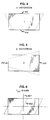
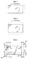
- FIGS. 1-8 Primary parameters of misregistration are graphically depicted in the FIGS. 1-8 which illustrate the various primary categories, established according to the invention, within the eight-parameter model or framework used in the illustrative process monitoring and control system.
- the eight-parameter model of misregistration is descriptive of how well the patterns on a panel or phototool are registered and is amenable to determining the causes of misregistration. (Patterns on a panel may include drilled holes, copper features or solder mask features, while patterns on a phototool are the opaque features imprinted on the phototool.)
- the eight parameters are divided, according to the invention, into two primary classes; rigid body displacements and material deformation dimensional changes.
- the rigid body displacements are directional shifts and include the x-shift, y-shift and rotation.
- a change in a horizontal location x or x-shift (designated ⁇ X) is shown in FIG. 1.
- the central origin 101 of the pattern is displaced ⁇ X to point 102.
- Solid line 110 represents the correct alignment and dotted line 111 represents the displaced pattern object.
- a vertical location change ⁇ Y or y-shift is shown in FIG. 2.
- the actual pattern 211 is displaced from the solid line reference boundary 210 by ⁇ Y.
- Both ⁇ X and ⁇ Y are independent of one another to the extent that a change in one location x or y is not a direct influence on the change in location along the axes y or x , respectively.
- the pattern and reference center points are shifted away from one another but the shape and area of the pattern remains unaltered.
- the third rigid body parameter is shown in FIG. 3. It involves a simple angular change (rotation) ⁇ of the pattern. If rotation alone occurs, the centers 310 of the pattern and reference are not affected and remain concordant with one another. Rotation often occurs in conjunction with x- and y-shifts.
- Deformation parameters are related to changes in the shape and form dimensions of the pattern.
- Two deformation parameters shown in FIGS. 4 and 5, are designated as the alpha ( ⁇ ) and beta ( ⁇ ) parameters. Each of these parameters involves a stretch and contraction along the same axis of the pattern but displaced to opposing sides of the pattern as shown in FIGS. 4 and 5.
- the alpha distortion shown in FIG. 4
- the top edge 401 has been stretched while the lower edge 402 has shrunk.
- the left edge 502 has shrunk and the right edge 503 has expanded.
- Shear another deformation parameter shown in FIG. 6, involves a skewing of the vertical axis 601 with respect to the horizontal axis 602. It is symbolically designated ⁇ XY and it results in a deformation of the pattern that causes its shape to depart from a right angled parallelogram.
- FIGS. 7 and 8 disclose dimensional changes in the pattern along the x-and y-axis in which the respective pattern and reference centers 701 and 801 are not shifted relative to each other. These changes in dimension are designated ⁇ X and ⁇ Y and are normally uniform over the entire pattern. They may be due to temperature and humidity changes or other causes that cause corresponding changes along the x- and y-axis.
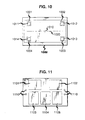
- FIG. 10 One particular pattern of fiducials used in the illustrative embodiment is shown in FIG. 10 and is discussed below. Given the U and V displacements of the four measured fiducials, the eight parameters are solved from a polynomial series. Two polynomial series are used to express each U and V displacement in terms of four coefficient values which are selected to describe how one pattern is registered to another in terms that are physically significant. Any displacements between corresponding points on two superimposed patterns are related to combinations of rigid body translations and rotations and to specific types of material deformations of the patterns.
- Occurrences of misregistrations are detected by the displacements of four fiducials relative to a standard of reference.
- the reference fiducials are engraved on a reference glass plate.
- a schematic of the fiducials used in the illustrative embodiment is shown in FIG. 10 and comprises the four square markers or reference fiducials 1001-1004 engraved on the reference glass 1000.
- the rectangular boxes 1011-1014 overlaid thereon represent the fiducials that are on the phototool or other item and are being compared to the reference fiducials.
- the center coordinate point 1010 of the reference is the master reference frame point from which the horizontal and vertical displacements are respectively measured.
- the reference center 1010 is selected as the controlling reference point in the embodiment herein because it is easy to align with and permits a more uniformly accurate registration over the extent of the panel.
- Apparatus for aligning panels and phototool to a common center 1010 and a common axis 1020 reference has been disclosed in my prior patent 4,793,052 issued December 27, 1988 which discloses a method for positioning a panel and its phototool.
- Positioning apparatus engages tooling features (i.e., holes) in the panel to align and secure one panel to a machine reference.
- the method disclosed therein uses one major axis and a reference origin which is at the panel center.
- Displacements occurring in panel features are in general smaller than for other positioning systems that use other reference origins because a center origin minimizes the maximum registration error caused by various deformations.
- Another advantage of this method is the virtual elimination of positioning backlash which detracts from many mechanical positioning schemes. This elimination of backlash in the positioning significantly enhances the performance of the metrology system disclosed herein.
- a typical panel layout for processing may include a plurality of individual printed circuit board layouts 1101-1105 on the panel. These five printed circuit board layouts are positioned as shown on the panel. Tooling features comprising the paired holes 1110 at opposite edges of the panel allow its positioning for processing, as per the methods disclosed in the 4,793,052 patent which is included herein by reference.
- the metrology system initially measures the offset of phototool or panel fiducials from reference fiducials. These offsets are converted to parameters of a model of the deformation and rigid position displacements of a single panel. By further converting these offset measurements into a set of advanced parameters, the physical causes of misregistration are identified. Long term trends are identified by analysis of these advanced parameters for aggregates of several lot samples.
- the flow diagram of this metrology process is shown in FIG. 12. This may be implemented in a stored program controlled system such as shown in FIG. 16.
- a lot sample is defined for testing per the instructions of block 1203.
- the measurement process begins in block 1205 by comparing the registration of the fiducials in the corners of the panel phototool or tool with the absolute reference fiducials.
- the U and V fiducial offsets in each of the four corners are measured and recorded in a data base, as per the instructions of block 1205.
- this data base is stored in a data processing computing device.
- the flow process for deriving the advanced parameters and analyzing the causes of detected misregistrations is disclosed in the flowcharts of FIGS. 13 and 14.
- the offset measurements are read from a data base and converted to the primary parameters by the instructions of block 1303.
- These primary parameter values are used, per the instructions of block 1305, to derive the averages of ⁇ X, ⁇ Y and ⁇ which represent the rigid body translations. These averages are designated ⁇ X ⁇ , ⁇ Y ⁇ and ⁇ ⁇ .
- the range and standard deviation are different but statistically proportional measures of the variability within a set of data. Choosing whether to use the standard deviation or the range depends upon the physical requirements of the production process and the level of training of the process operators.
- the lot range (maximum minus minimum within a lot) is typically used on operator-level control charts.
- the standard deviation is used for long term trend analysis, which will be described later.
- the lot ranges are calculated from the measurements as per the instructions of block 1307. These values are designated R ⁇ X , R ⁇ Y , and R ⁇ .
- Advanced parameters computed from the material deformation primary parameters ( ⁇ X , ⁇ Y , ⁇ XY , ⁇ , ⁇ ) are derived as per instructions of the block 1311.
- the advanced parameters ⁇ X ⁇ , ⁇ Y ⁇ , ⁇ XY ⁇ , ⁇ ⁇ and ⁇ ⁇ are calculated by determining the average values of ⁇ X ⁇ Y ⁇ XY , ⁇ and ⁇ respectively.
- the advanced parameters R ⁇ X , R ⁇ Y , R ⁇ XY , R ⁇ and R ⁇ the lot ranges of the primary patterns, are then calculated as per the instructions of the block 1313.
- the decision process of block 1317 investigates of the average values of ⁇ X ⁇ , ⁇ Y ⁇ and ⁇ ⁇ exceed control limits; these limits may be selected or calculated from prior data. If these control limits are exceeded, an unacceptable registration condition has been detected.
- Setup error representing repeatable hardware and/or procedural problems, is investigated as a probable cause according to the instructions of block 1319. This probable cause is listed, as per the instructions of block 1321, and corrective action concerning procedures and hardware corrections is suggested. In photoprint operations, for example, one possible cause of setup error would be inaccurate tooling holes in the phototool; this contribution can be accurately determined by (re)measuring the phototool.
- the process flow proceeds to the decision of block 1323 which determines if the lot ranges R ⁇ X , R ⁇ Y and R ⁇ exceed the control limits; these limits may be selected or calculated from prior data. If these control limits are exceeded, the flow proceeds to block 1325 whose instructions evaluate the data for probable tooling error. Its causes may be incorrect installation and/or slack in the panel or phototool positioning apparatus. These items are then subjected to mechanical inspection by personnel, as per the probable causes listed, in response to the instructions of the block 1327.
- the calculated advanced parameters are evaluated to determine if unacceptable conditions of material deformations exist and to indicate the probable causes of such deformations.
- Process flow proceeds to the decision block 1329 to determine of any of the advanced parameter values representing average material deformations ( ⁇ X ⁇ , ⁇ Y ⁇ , ⁇ XY ⁇ , ⁇ ⁇ , ⁇ ⁇ ⁇ ) exceed their control limits which may be calculated or pre-selected. If these limits are exceeded, the flow proceeds to the instructions of the block 1331 to evaluate for average deformation error.
- Causes include non-standard environmental conditions of the phototool, panel product or processing machine(s).
- Long term trend analysis is based on collected data for a plurality of lot samples. Long term trend analysis allows evaluation and fine-tuning of all the registration processes; it is performed according to the flow process disclosed in FIG. 15. Using data from many lots enhances the statistical accuracy of the diagnostics, and facilitates identification of gradual variations and small but statistically significant biases.
- Displacement measurements stored from a plurality of lot samples is accumulated according to the instructions of the block 1503. If desired, the data can be sorted to select or eliminate lots according to desired combinations of various criteria, e.g. product family (Double-Sided vs Multilayer) using the menu-driven instructions of block 1505. Extended period parameters are calculated for the accumulated data as per the instructions of block 1507. These values fall into three basic types for each of the eight primary parameters, e.g. ⁇ X. Ensemble averages, e.g. ⁇ X ⁇ ⁇ , show any long term average bias. Ensemble standard deviations of lot averages, e.g. ⁇ ⁇ X ⁇ , represent the standard deviations of averages within a lot, and show any long term variability between lots. Ensemble averages of lot standard deviations, e.g. ⁇ ⁇ X ⁇ , show the average variability within lots, averaged over many lots. The calculated results are saved in a file, both human and machine readable, by the instructions in block 1509.
- the multiple lot parameters calculated in block 1507 are compared to control limits by the process of decision block 1511. If any of these limits are exceeded, the relavent parameters and their control limits are listed, along with probable causes of error, as per the instructions of block 1515.
- the ensemble averages for the rigid body parameters ⁇ X, ⁇ Y, ⁇ (e.g. ⁇ X ⁇ ⁇ ), and their ensemble averages of lot standard deviations (e.g. ⁇ ⁇ X ⁇ ) have causes including but not limited to those listed by blocks 1321 and 1327 respectively.
- the ensemble averages for the material deformations ⁇ X , ⁇ Y , ⁇ XY , ⁇ , ⁇ e.g.
- FIG. 16 A measurement system suitable for use in the described metrology system described herein is shown schematically in FIG. 16.
- a transparent reference plate 1610 with reference fiducials 1611-1614 in the four corners is mounted above four video cameras 1621-1624 with the fiducials in their field of vision.
- the pattern 1630 includes its own complementary fiducials 1631-1634 located in its corners.
- the fiducials 1631-1634 are measured with respect to the fiducials 1611-1614 of the reference plate to determine the U and V displacements.
- one pattern 1630 is overlaid on top of the reference plate 1610 and positioned by application of the method disclosed in the aforementioned 4,793,052 patent.
- Engaging elements 1691-1694 controlled by a mechanism such as disclosed in the (052) patent engage holes punched or drilled in the pattern and postion it so that its center and an axis through that center is congruent with a center of the reference plate and an axis passing through that center. Details of the positioning mechanism and the operation there of may be obtained from the (052) patent whose teaching and disclosure is incorporated herein by reference.
- the displacements of the pattern fiducials from the reference fiducials are measured by a computer control system 1650 from the video images produced by the camera 1621-1624.
- the computer control system 1650 includes input means 1651 for collecting the measured fiducial displacements and a control terminal 1652 for accepting operator input.
- a display terminal 1653 is included for displaying basic measurements, calculated results and graphical depiction thereof.
- a bus 1655 interconnects these units to each other and to a processor 1656, a stored program unit 1657 and a memory unit 1658.
Landscapes
- Engineering & Computer Science (AREA)
- Manufacturing & Machinery (AREA)
- Microelectronics & Electronic Packaging (AREA)
- Operations Research (AREA)
- Length Measuring Devices By Optical Means (AREA)
- Machine Tool Sensing Apparatuses (AREA)
- Multi-Process Working Machines And Systems (AREA)
- General Factory Administration (AREA)
- Container, Conveyance, Adherence, Positioning, Of Wafer (AREA)
- Management, Administration, Business Operations System, And Electronic Commerce (AREA)
- Length Measuring Devices With Unspecified Measuring Means (AREA)
Claims (2)
- Verfahren zum Messen der Positionen vom Strukturen eines Plattenelements und Identifizieren von Ursachen für falsche Positionen durch Analysieren einer Messung der Strukturen, mit folgenden Schritten:Bereitstellen einer transparenten Referenztafel (1610) mit Referenzjustiermarken (1611-1614) an ihren Ecken, wobei die Referenzjustiermarken um eine Referenzmitte (1010) der Referenztafel herum zentriert sind;Vorbereiten eines fertigungsverarbeiteten transparenten Plattenelements (1630) mit Arbeitsjustiermarken (1631-1634) an seinen Ecken, wobei die Arbeitsjustiermarken um eine Mitte der Platte herum zentriert sind;Plazieren des fertigungsverarbeiteten transparenten Plattenelements auf die transparente Referenztafel unter Ausrichtung ihrer jeweiligen Mitten und Messen von Versatzverschiebungen der Arbeitsjustiermarken von den Referenzjustiermarken unter Verwendung von Maschinensichtkontrollausrüstung (1621-1624) und Speichern der Versatzverschiebungen in einem Rechnerspeicher (1658);Verwenden von Anweisungen eines gespeicherten Programms (1657) zumUmwandeln der gemessenen Versatzverschiebungen in eine Menge von Starrkörper-Übergangsparametern und Materialverformungs-Übergangsparametern (1209);Übertragen des Starrkörper-Übergangsparameters und der Verformungsübergangsparameter in mehrere zusammengesetzte Verzerrungsparameter, die Durchschnittswerte und Abweichungswerte der Starrkörperparameter und Durchschnittswerte und Abweichungen der Materialverformungsparameter darstellen;Vergleichen der mehreren Verzerrungsparameter mit vorbestimmten Grenzwerten;Bestimmen von Ursachen für die Versatzverschiebungen durch Korrelieren der die vorbestimmten Grenzwerte übersteigenden mehreren Verzerrungsparameter mit einer tabellenartigen Liste von mit den mehreren Verzerrungsparametern in Beziehung stehenden wahrscheinlichen Verschiebungsursachen und Zuweisen dieser Ursachen zu der Verschiebung (1211),Übermitteln der zugewiesenen Ursachen (1213) über eine Anzeigevorrichtung.
- Verfahren nach Anspruch 1, einschließlich des weiteren Schritts des Umwandelns gemessener Verschiebungen in Starrkörper- und Verformungsparameter durch Lösen von Polynomreihenentwicklungsgleichungen.
Applications Claiming Priority (2)
| Application Number | Priority Date | Filing Date | Title |
|---|---|---|---|
| US07/576,304 US5206820A (en) | 1990-08-31 | 1990-08-31 | Metrology system for analyzing panel misregistration in a panel manufacturing process and providing appropriate information for adjusting panel manufacturing processes |
| US576304 | 1990-08-31 |
Publications (3)
| Publication Number | Publication Date |
|---|---|
| EP0473363A2 EP0473363A2 (de) | 1992-03-04 |
| EP0473363A3 EP0473363A3 (en) | 1992-09-02 |
| EP0473363B1 true EP0473363B1 (de) | 1997-04-09 |
Family
ID=24303860
Family Applications (1)
| Application Number | Title | Priority Date | Filing Date |
|---|---|---|---|
| EP91307732A Expired - Lifetime EP0473363B1 (de) | 1990-08-31 | 1991-08-22 | Messsystem zur Analyse von Lageabweichungen einer Platte in einem Plattenherstellungsverfahren und zum Liefern von geeigneten Informationen zur Anpassung der Plattenherstellungsverfahren |
Country Status (4)
| Country | Link |
|---|---|
| US (1) | US5206820A (de) |
| EP (1) | EP0473363B1 (de) |
| JP (1) | JP2824351B2 (de) |
| DE (1) | DE69125550T2 (de) |
Families Citing this family (48)
| Publication number | Priority date | Publication date | Assignee | Title |
|---|---|---|---|---|
| US6067379A (en) * | 1988-12-09 | 2000-05-23 | Cognex Corporation | Method and apparatus for locating patterns in an optical image |
| DE4406538A1 (de) * | 1994-02-28 | 1995-08-31 | Mania Gmbh | Leiterplatten-Prüfeinrichtung mit Prüfadapter und Verfahren zum Einstellen desselben |
| US5602937A (en) * | 1994-06-01 | 1997-02-11 | Cognex Corporation | Methods and apparatus for machine vision high accuracy searching |
| JPH0891543A (ja) * | 1994-09-28 | 1996-04-09 | Omron Corp | 画像処理方法およびその装置 |
| JP3409493B2 (ja) * | 1995-03-13 | 2003-05-26 | ソニー株式会社 | マスクパターンの補正方法および補正装置 |
| US5801966A (en) * | 1995-07-24 | 1998-09-01 | Cognex Corporation | Machine vision methods and articles of manufacture for determination of convex hull and convex hull angle |
| US6026176A (en) | 1995-07-25 | 2000-02-15 | Cognex Corporation | Machine vision methods and articles of manufacture for ball grid array inspection |
| US5757956A (en) * | 1995-10-31 | 1998-05-26 | Cognex Corp. | Template rotating method for locating bond pads in an image |
| US5754679A (en) * | 1995-10-31 | 1998-05-19 | Cognex Corp. | Image rotating method for locating bond pads in an image |
| US5845007A (en) * | 1996-01-02 | 1998-12-01 | Cognex Corporation | Machine vision method and apparatus for edge-based image histogram analysis |
| US5872870A (en) * | 1996-02-16 | 1999-02-16 | Cognex Corporation | Machine vision methods for identifying extrema of objects in rotated reference frames |
| US5909504A (en) * | 1996-03-15 | 1999-06-01 | Cognex Corporation | Method of testing a machine vision inspection system |
| US6298149B1 (en) | 1996-03-21 | 2001-10-02 | Cognex Corporation | Semiconductor device image inspection with contrast enhancement |
| US5949901A (en) * | 1996-03-21 | 1999-09-07 | Nichani; Sanjay | Semiconductor device image inspection utilizing image subtraction and threshold imaging |
| US6259827B1 (en) | 1996-03-21 | 2001-07-10 | Cognex Corporation | Machine vision methods for enhancing the contrast between an object and its background using multiple on-axis images |
| US5978502A (en) * | 1996-04-01 | 1999-11-02 | Cognex Corporation | Machine vision methods for determining characteristics of three-dimensional objects |
| JP3011401B2 (ja) * | 1996-08-29 | 2000-02-21 | 日本電産リード株式会社 | 上側治具位置決め機構付きプリント基板検査装置および上側治具位置決め方法 |
| US6137893A (en) * | 1996-10-07 | 2000-10-24 | Cognex Corporation | Machine vision calibration targets and methods of determining their location and orientation in an image |
| US5960125A (en) | 1996-11-21 | 1999-09-28 | Cognex Corporation | Nonfeedback-based machine vision method for determining a calibration relationship between a camera and a moveable object |
| US5953130A (en) * | 1997-01-06 | 1999-09-14 | Cognex Corporation | Machine vision methods and apparatus for machine vision illumination of an object |
| US6075881A (en) * | 1997-03-18 | 2000-06-13 | Cognex Corporation | Machine vision methods for identifying collinear sets of points from an image |
| US5974169A (en) * | 1997-03-20 | 1999-10-26 | Cognex Corporation | Machine vision methods for determining characteristics of an object using boundary points and bounding regions |
| US6141033A (en) * | 1997-05-15 | 2000-10-31 | Cognex Corporation | Bandwidth reduction of multichannel images for machine vision |
| US6608647B1 (en) | 1997-06-24 | 2003-08-19 | Cognex Corporation | Methods and apparatus for charge coupled device image acquisition with independent integration and readout |
| US5978080A (en) * | 1997-09-25 | 1999-11-02 | Cognex Corporation | Machine vision methods using feedback to determine an orientation, pixel width and pixel height of a field of view |
| US6025854A (en) * | 1997-12-31 | 2000-02-15 | Cognex Corporation | Method and apparatus for high speed image acquisition |
| US6282328B1 (en) | 1998-01-28 | 2001-08-28 | Cognex Corporation | Machine vision systems and methods for morphological transformation of an image with non-uniform offsets |
| US6236769B1 (en) | 1998-01-28 | 2001-05-22 | Cognex Corporation | Machine vision systems and methods for morphological transformation of an image with zero or other uniform offsets |
| US6381375B1 (en) | 1998-02-20 | 2002-04-30 | Cognex Corporation | Methods and apparatus for generating a projection of an image |
| US6215915B1 (en) | 1998-02-20 | 2001-04-10 | Cognex Corporation | Image processing methods and apparatus for separable, general affine transformation of an image |
| US6516092B1 (en) | 1998-05-29 | 2003-02-04 | Cognex Corporation | Robust sub-model shape-finder |
| US6381366B1 (en) | 1998-12-18 | 2002-04-30 | Cognex Corporation | Machine vision methods and system for boundary point-based comparison of patterns and images |
| US6687402B1 (en) | 1998-12-18 | 2004-02-03 | Cognex Corporation | Machine vision methods and systems for boundary feature comparison of patterns and images |
| US6684402B1 (en) | 1999-12-01 | 2004-01-27 | Cognex Technology And Investment Corporation | Control methods and apparatus for coupling multiple image acquisition devices to a digital data processor |
| US6748104B1 (en) | 2000-03-24 | 2004-06-08 | Cognex Corporation | Methods and apparatus for machine vision inspection using single and multiple templates or patterns |
| JP4485667B2 (ja) | 2000-08-21 | 2010-06-23 | パナソニック株式会社 | 部品実装装置のオフセット測定用基板及び部品実装装置のオフセット測定方法 |
| US6581202B1 (en) * | 2000-11-10 | 2003-06-17 | Viasystems Group, Inc. | System and method for monitoring and improving dimensional stability and registration accuracy of multi-layer PCB manufacture |
| US7006669B1 (en) | 2000-12-31 | 2006-02-28 | Cognex Corporation | Machine vision method and apparatus for thresholding images of non-uniform materials |
| US6804388B2 (en) * | 2001-03-14 | 2004-10-12 | Maniabarco, Inc. | Method and apparatus of registering a printed circuit board |
| US7089160B2 (en) * | 2002-01-08 | 2006-08-08 | International Business Machines Corporation | Model for modifying drill data to predict hole locations in a panel structure |
| DK2078954T3 (en) * | 2002-12-10 | 2017-08-07 | Chep Technology Pty Ltd | Automated pallet inspection |
| US7639861B2 (en) | 2005-09-14 | 2009-12-29 | Cognex Technology And Investment Corporation | Method and apparatus for backlighting a wafer during alignment |
| US8111904B2 (en) * | 2005-10-07 | 2012-02-07 | Cognex Technology And Investment Corp. | Methods and apparatus for practical 3D vision system |
| US8162584B2 (en) * | 2006-08-23 | 2012-04-24 | Cognex Corporation | Method and apparatus for semiconductor wafer alignment |
| JP5303230B2 (ja) * | 2008-09-29 | 2013-10-02 | 株式会社日立ハイテクノロジーズ | 画像処理システム、及び走査型電子顕微鏡装置 |
| JP6498564B2 (ja) * | 2015-08-20 | 2019-04-10 | 日置電機株式会社 | 処理装置、基板検査装置、処理方法および基板検査方法 |
| US10565697B2 (en) * | 2017-10-22 | 2020-02-18 | Kla-Tencor Corporation | Utilizing overlay misregistration error estimations in imaging overlay metrology |
| CN212936279U (zh) * | 2020-07-08 | 2021-04-09 | 瑞声科技(新加坡)有限公司 | 用于lcp基板的内层板结构及lcp基板 |
Family Cites Families (18)
| Publication number | Priority date | Publication date | Assignee | Title |
|---|---|---|---|---|
| US4259019A (en) * | 1971-03-22 | 1981-03-31 | Kasper Instruments, Inc. | Apparatus for the automatic alignment of two superimposed objects, for example a semiconductor wafer and a transparent mask |
| US3955072A (en) * | 1971-03-22 | 1976-05-04 | Kasper Instruments, Inc. | Apparatus for the automatic alignment of two superimposed objects for example a semiconductor wafer and a transparent mask |
| JPS5923467B2 (ja) * | 1979-04-16 | 1984-06-02 | 株式会社日立製作所 | 位置検出方法 |
| JPS5628650A (en) * | 1979-08-16 | 1981-03-20 | Mitsubishi Petrochemical Co | Method of crushing epoxy resin or epoxy resin composition |
| JPS5994419A (ja) * | 1982-11-19 | 1984-05-31 | Canon Inc | 分割焼付け装置におけるアライメント方法 |
| US4713784A (en) * | 1983-07-04 | 1987-12-15 | Canon Kabushiki Kaisha | Alignment apparatus |
| US4536239A (en) * | 1983-07-18 | 1985-08-20 | Nicolet Instrument Corporation | Multi-layer circuit board inspection system |
| GB2146427B (en) * | 1983-08-01 | 1987-10-21 | Canon Kk | Semiconductor manufacture |
| JPS61174717A (ja) * | 1985-01-30 | 1986-08-06 | Canon Inc | 位置合わせ装置 |
| US4805123B1 (en) * | 1986-07-14 | 1998-10-13 | Kla Instr Corp | Automatic photomask and reticle inspection method and apparatus including improved defect detector and alignment sub-systems |
| US4697087A (en) * | 1986-07-31 | 1987-09-29 | The Perkin-Elmer Corporation | Reverse dark field alignment system for scanning lithographic aligner |
| JPH0761599B2 (ja) * | 1986-10-08 | 1995-07-05 | 株式会社日立製作所 | 製造設備監視方法 |
| US4774640A (en) * | 1987-03-26 | 1988-09-27 | Montean Jr John | Illuminating device for determining dimensional integrity of material working tools |
| JPS63310113A (ja) * | 1987-06-11 | 1988-12-19 | Nec Corp | 半導体集積回路の製造装置 |
| JPS63310116A (ja) * | 1987-06-12 | 1988-12-19 | Hitachi Ltd | 半導体チツプパタンの基準位置合せ方法 |
| US4793052A (en) * | 1987-11-13 | 1988-12-27 | American Telephone And Telegraph Company, At&T Laboratories | Method for positioning a panel |
| US4894606A (en) * | 1988-07-07 | 1990-01-16 | Paur Tom R | System for measuring misregistration of printed circuit board layers |
| US4918380A (en) * | 1988-07-07 | 1990-04-17 | Paur Tom R | System for measuring misregistration |
-
1990
- 1990-08-31 US US07/576,304 patent/US5206820A/en not_active Expired - Fee Related
-
1991
- 1991-08-22 EP EP91307732A patent/EP0473363B1/de not_active Expired - Lifetime
- 1991-08-22 DE DE69125550T patent/DE69125550T2/de not_active Expired - Fee Related
- 1991-08-30 JP JP24407291A patent/JP2824351B2/ja not_active Expired - Fee Related
Also Published As
| Publication number | Publication date |
|---|---|
| JPH04315557A (ja) | 1992-11-06 |
| EP0473363A3 (en) | 1992-09-02 |
| EP0473363A2 (de) | 1992-03-04 |
| DE69125550D1 (de) | 1997-05-15 |
| DE69125550T2 (de) | 1997-07-31 |
| US5206820A (en) | 1993-04-27 |
| JP2824351B2 (ja) | 1998-11-11 |
Similar Documents
| Publication | Publication Date | Title |
|---|---|---|
| EP0473363B1 (de) | Messsystem zur Analyse von Lageabweichungen einer Platte in einem Plattenherstellungsverfahren und zum Liefern von geeigneten Informationen zur Anpassung der Plattenherstellungsverfahren | |
| DE69514016T2 (de) | Bohrkoordinaten-Optimierung für mehrschichtige Leiterplatten | |
| EP0457843B1 (de) | Verfahren sowie gerät zur messung der schichtanordnung in einem halbleiter-wafer | |
| US5134575A (en) | Method of producing numerical control data for inspecting assembled printed circuit board | |
| US4680627A (en) | Apparatus for checking patterns on printed circuit boards | |
| US6581202B1 (en) | System and method for monitoring and improving dimensional stability and registration accuracy of multi-layer PCB manufacture | |
| US5111406A (en) | Method for determining drill target locations in a multilayer board panel | |
| US5377404A (en) | Method for fabricating a multi-layer printed circuit board | |
| US11176635B2 (en) | Automatic programming of solder paste inspection system | |
| EP0264243A2 (de) | Verfahren und System für Vorbohrverarbeitung von mehrlagig gedruckten Schaltungsplatten | |
| US7089160B2 (en) | Model for modifying drill data to predict hole locations in a panel structure | |
| DE112006003089T5 (de) | System und Verfahren zum Montieren von elektronischen Bauelementen | |
| JP4377782B2 (ja) | 実装基板の検査方法および同装置 | |
| CN116858092A (zh) | 检测视觉系统偏差的方法及电路板加工设备 | |
| CN116634134A (zh) | 一种成像系统校准的方法、装置、存储介质及电子设备 | |
| KR100607823B1 (ko) | 인쇄 회로 기판 품질 관리 방법 | |
| KR101570023B1 (ko) | 인쇄 회로 기판 자동 분류 방법 | |
| JPH04345445A (ja) | プリント基板作業装置およびそれの送り装置誤差検出装置 | |
| JP2001013189A (ja) | 回路基板検査装置の制御方法 | |
| JP4448417B2 (ja) | 実装基板の検査用データ作成方法 | |
| JP4537810B2 (ja) | 実装基板の検査用データ作成方法 | |
| WO1998042167A2 (de) | Verfahren und vorrichtung zum vermessen einer einrichtung zur herstellung von elektrischen baugruppen | |
| CN118913159A (zh) | 一种用于测量层偏数据的方法 | |
| JPH03136708A (ja) | プリント基板穴明機の穴明加工システム及びプリント基板穴明機の穴明加工システムにおける円の中心座標測定方法 | |
| Rodriguez et al. | Calibration and alignmenttechniques for automated inspection of printed circuit patterns |
Legal Events
| Date | Code | Title | Description |
|---|---|---|---|
| PUAI | Public reference made under article 153(3) epc to a published international application that has entered the european phase |
Free format text: ORIGINAL CODE: 0009012 |
|
| AK | Designated contracting states |
Kind code of ref document: A2 Designated state(s): DE FR GB IT NL |
|
| PUAL | Search report despatched |
Free format text: ORIGINAL CODE: 0009013 |
|
| AK | Designated contracting states |
Kind code of ref document: A3 Designated state(s): DE FR GB IT NL |
|
| 17P | Request for examination filed |
Effective date: 19930219 |
|
| RAP3 | Party data changed (applicant data changed or rights of an application transferred) |
Owner name: AT&T CORP. |
|
| 17Q | First examination report despatched |
Effective date: 19950324 |
|
| GRAG | Despatch of communication of intention to grant |
Free format text: ORIGINAL CODE: EPIDOS AGRA |
|
| GRAH | Despatch of communication of intention to grant a patent |
Free format text: ORIGINAL CODE: EPIDOS IGRA |
|
| GRAH | Despatch of communication of intention to grant a patent |
Free format text: ORIGINAL CODE: EPIDOS IGRA |
|
| GRAA | (expected) grant |
Free format text: ORIGINAL CODE: 0009210 |
|
| AK | Designated contracting states |
Kind code of ref document: B1 Designated state(s): DE FR GB IT NL |
|
| ITF | It: translation for a ep patent filed | ||
| ET | Fr: translation filed | ||
| REF | Corresponds to: |
Ref document number: 69125550 Country of ref document: DE Date of ref document: 19970515 |
|
| PLBE | No opposition filed within time limit |
Free format text: ORIGINAL CODE: 0009261 |
|
| STAA | Information on the status of an ep patent application or granted ep patent |
Free format text: STATUS: NO OPPOSITION FILED WITHIN TIME LIMIT |
|
| 26N | No opposition filed | ||
| REG | Reference to a national code |
Ref country code: GB Ref legal event code: IF02 |
|
| PGFP | Annual fee paid to national office [announced via postgrant information from national office to epo] |
Ref country code: DE Payment date: 20070822 Year of fee payment: 17 |
|
| PGFP | Annual fee paid to national office [announced via postgrant information from national office to epo] |
Ref country code: GB Payment date: 20070823 Year of fee payment: 17 |
|
| PGFP | Annual fee paid to national office [announced via postgrant information from national office to epo] |
Ref country code: NL Payment date: 20070814 Year of fee payment: 17 Ref country code: IT Payment date: 20070824 Year of fee payment: 17 |
|
| PGFP | Annual fee paid to national office [announced via postgrant information from national office to epo] |
Ref country code: FR Payment date: 20070823 Year of fee payment: 17 |
|
| GBPC | Gb: european patent ceased through non-payment of renewal fee |
Effective date: 20080822 |
|
| NLV4 | Nl: lapsed or anulled due to non-payment of the annual fee |
Effective date: 20090301 |
|
| PG25 | Lapsed in a contracting state [announced via postgrant information from national office to epo] |
Ref country code: NL Free format text: LAPSE BECAUSE OF NON-PAYMENT OF DUE FEES Effective date: 20090301 |
|
| REG | Reference to a national code |
Ref country code: FR Ref legal event code: ST Effective date: 20090430 |
|
| PG25 | Lapsed in a contracting state [announced via postgrant information from national office to epo] |
Ref country code: IT Free format text: LAPSE BECAUSE OF NON-PAYMENT OF DUE FEES Effective date: 20080822 Ref country code: DE Free format text: LAPSE BECAUSE OF NON-PAYMENT OF DUE FEES Effective date: 20090303 Ref country code: FR Free format text: LAPSE BECAUSE OF NON-PAYMENT OF DUE FEES Effective date: 20080901 |
|
| PG25 | Lapsed in a contracting state [announced via postgrant information from national office to epo] |
Ref country code: GB Free format text: LAPSE BECAUSE OF NON-PAYMENT OF DUE FEES Effective date: 20080822 |